Thuli Tables The Junior Portable User manual

The Junior Portable
Owner's Manual
TABLE OF CONTENTS
Table of Contents
Introduction & Warranty . . . . . . . . . . . . . . . 2
Identication of Parts . . . . . . . . . . . . . . 3 - 5
Table Set-Up . . . . . . . . . . . . . . . . . . . . . . 6 - 8
Heapiece Operation . . . . . . . . . . . . . . . 9 - 12
Table Operation . . . . . . . . . . . . . . . . . 12 - 14
Table Fold-Down . . . . . . . . . . . . . . . . . . . 15
Accessories . . . . . . . . . . . . . . . . . . . . 16 - 17
Care & Maintenance . . . . . . . . . . . . . . . . . . 18
Ofce Art . . . . . . . . . . . . . . . . . . . . . . . . . . 19
Overview of Products . . . . . . . . . . . . . Back
THULI TABLES
www.thulitables.com
youtube.com/thulitables
800-458-4854
facebook.com/thulitables

2Introduction & Warranty 2
Thank you for your purchase of a Junior portable table. We are pleased to
provide you with an aesthetically beautiful chiropractic adjusting table that
is versatile and precisely engineered. It has been inspected and tested right
down to the smallest detail before leaving our shop. We are condent that it
will provide you with many years of reliable service.
To familiarize you with the table and instruct you on its proper operation and
maintenance, please take the time to read this manual carefully.
Our products are covered by a one year warranty, which includes any defect in
workmanship, function and materials under normal wear and tear conditions.
If you have any questions or comments, please contact us. We look forward
to speaking with you!
Rick Thuli, D.C.
President
Sincerely,
Thuli Tables Dodgeville Wisconsin USA

3
Thoracic Section
Prone Arm Rest
Pelvic Cocking Lever
& Tension Control
Rod
Thoracic Cocking Lever
&Tension Control Rod
Ankle Rest
Locking Knob
Folding
Support Brace
(Left)
Identification of Table Parts 3
Piston
(adjustable)
Ankle Rest Pelvic Section
Extension
Note: Place weights over
the back leg crossbrace
for counterbalance.

4
Folding
Support Brace Remote Control
Paper
Tear-Off Bar
Identification of Table Parts in Folded Position 4
Headpiece
Paper
Ankle Rest
Extension
Thoracic Cocking Bar
Thoracic Cocking Bar
Thoracic Cocking Bar
Thoracic Cocking Bar
Pelvic Cocking Bar
Front Legs Piston
Remote Control
Lever
Thoracic
Slant Bar
Prone Arm Rest
Thoracic Cocking Lever
& Tension Control Rod
Back Legs
Pelvic Cocking Lever
& Tension Control Rod
Ankle Rest
Extension
Paper
Paper
Tear-Off Bar
Hanger

5
Pivot Block
Paper Hanger
Remote Control Lever
Piston Head
Adjustable Buckle for
Prone Arm Rest
Flexion /Extension Piston
Prone Arm Rest
Lowering Lever
T-Bar
Cocking Lever
Straight Drop/
Forward Motion Knob
Remote Control Cable
Piston Pin
Base Block
Tension Control Knob
(not visible)
Paper Hold-Down Wire
Paper Tear-Off Bar
Pin to close table &
attach headpiece
Pivot Pin
Identification of Headpiece Parts 5

6
REMOVE ANKLE REST EXTENSION
Lay the table onto its cushions. Remove the ankle rest
extension from its storage postion by slightly raising the
front legs.
1. Unfasten the Velcro strap from both ends and remove.
HEADPIECE ATTACHMENT
Table Set-Up 6
HEADPIECE ATTACHMENT (cont.)
Insert the ankle rest rods into their brackets and tighten down
with the locking knob (on the side of the table).
INSTALL ANKLE REST EXTENSION
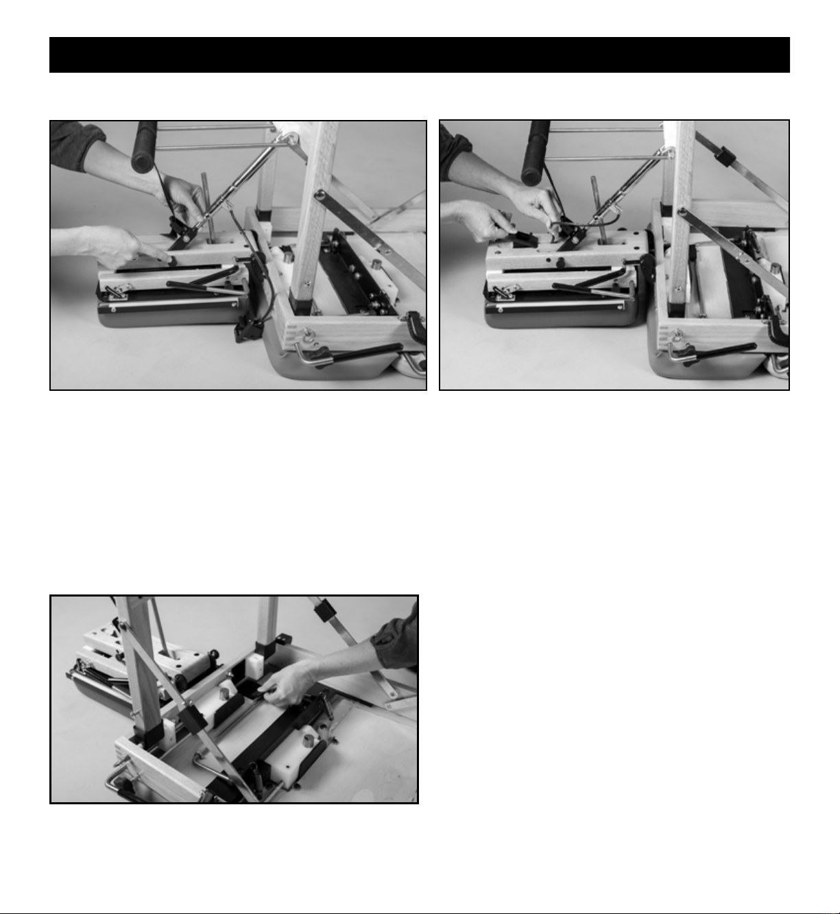
2. Lift the base block by grasping the lowering lever and raising it to
a 45 degree angle.
3. Grasp the end of the T-bar with your other hand. Insert it into the
hole in the locking link of the base block.
4. Lower the base block to a closed position by applying counter
clockwise (downward) torque to the lowering lever.

7
HEADPIECE ATTACHMENT (cont.)
1. Raise the front legs from their folded position by grasping
the horizontal crosspiece.
2. Straighten the folding leg support braces and lock them into
place by sliding the black brace locks over the brace joints.
Note: If the brace lock falls down off of the brace joint,
slide the lock back over the joint and exert a slight pressure
perpendicular to the brace at the brace lock. This will provide
sufcient friction to keep the brace lock in place.
5. Before raising the front legs from their folded position,
disengage the piston head from its locked position. Squeeze
the remote control lever and retract the piston head from the
hole in the frame.
FRONT LEG SET-UP
Table Set-Up 7
FRONT LEG SET-UP (cont.) BACK LEG SET-UP
Raise the back legs, straighten the braces and lock them into
place (same as the front legs).
8
Release the Velcro-secured thoracic section.
THORACIC SECTION RELEASE
Install the black remote control lever into the bottom of the
base block by inserting the cable into the narrow slot and tilt
the cable end of the lever into the slot until it snaps into place.
Note the milled nger recess for later removal of this lever
when folding up the table. Operating this lever will allow the
headpiece to lay ush with the table cushions.
Table Set-Up 8
REMOTE CONTROL LEVER ATTACHMENT
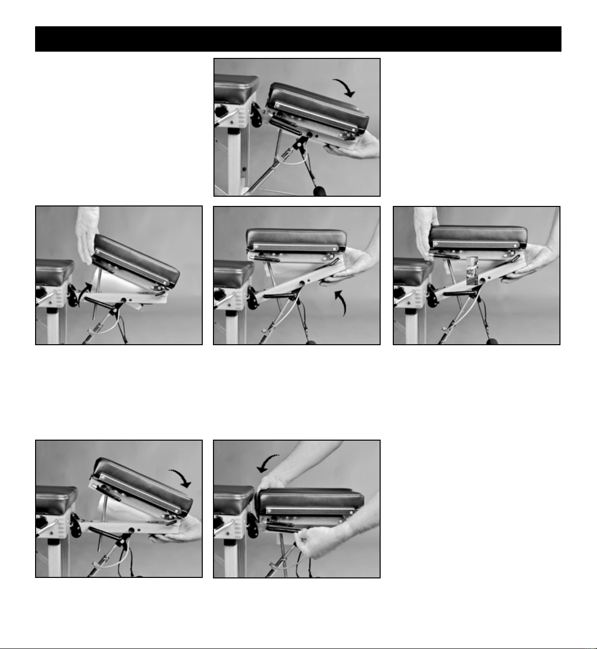
1. Swing the headpiece exion/extension piston down toward the
off-centered slot in the headpiece base block.
2. Remove the piston pin from the headpiece base block and
raise the front end of the headpiece to allow the piston to engage
the off-centered slot. Note: Operating the remote control lever
will allow you to rotate the piston head to align with the off-
centered slot.
3. Attach the exion/extension piston to the headpiece base block
by visually lining up the holes and re-inserting the piston pin.
PISTON ATTACHMENT

9
1. Install a standard 8.5" roll of headpiece
paper, as shown.
2. Raise the paper hold-down wire and
tear-off bar. Advance the paper and tuck
it between the cushions.
3. Lower the hold-down wire between the
cushions, lower the tear-off bar and tear
off excess paper. See step 5.
4. To advance the headpiece paper, raise
the tear-off bar, hold your nger on the
paper hold-down wire and pull the
paper across the cushions. Pulling the
paper in an upward direction will
reduce friction making it easier to pull.
CORRECT TABLE POSITIONING BEFORE SETTING UPRIGHT
5. To tear off used headpiece paper, use an
upward motion while holding down the
tear-off bar.
SET THE TABLE UPRIGHT: Tilt the table away from you and onto its feet.
HEADPIECE PAPER
Table Set-Up & Headpiece Operation 9
10
VERTICAL ELEVATION
VERTICAL LOWERING
2. Raise the front end of the headpiece by
operating the remote control lever.
1. Lower the front end of the headpiece by
operating the remote control lever, as in
exing or extending the headpiece.
2. Lower the back end of the headpiece by
lifting the headpiece lowering lever
rmly with one hand while gently lowering
the back end of the headpiece with your
other hand.
FLEXION AND EXTENSION
3. With practice, steps 1 and 2 can be
combined to vertically raise the headpiece
in one smooth motion.
IMPORTANT
Advise your patient before changing the
position of the headpiece. This is especially
important when lowering the back end of the
headpiece (step 2). Failure to do so may
result in its sudden drop, causing possible
alarm to the patient.
Flex and extend the headpiece by grasping
the front end of the headpiece and operating
the remote control lever on the underside of
the headpiece with your ngertips.
Headpiece Operation 10
1. Raise the back end of the headpiece
by lifting the red grip of the cocking
lever (without operating the lever).
Caution: Do not grasp the cushions to
raise the back end, which could stretch
and damage the small springs.
11
HEADPIECE CUSHION ADJUSTABILITY
HEADPIECE PORTABILITY
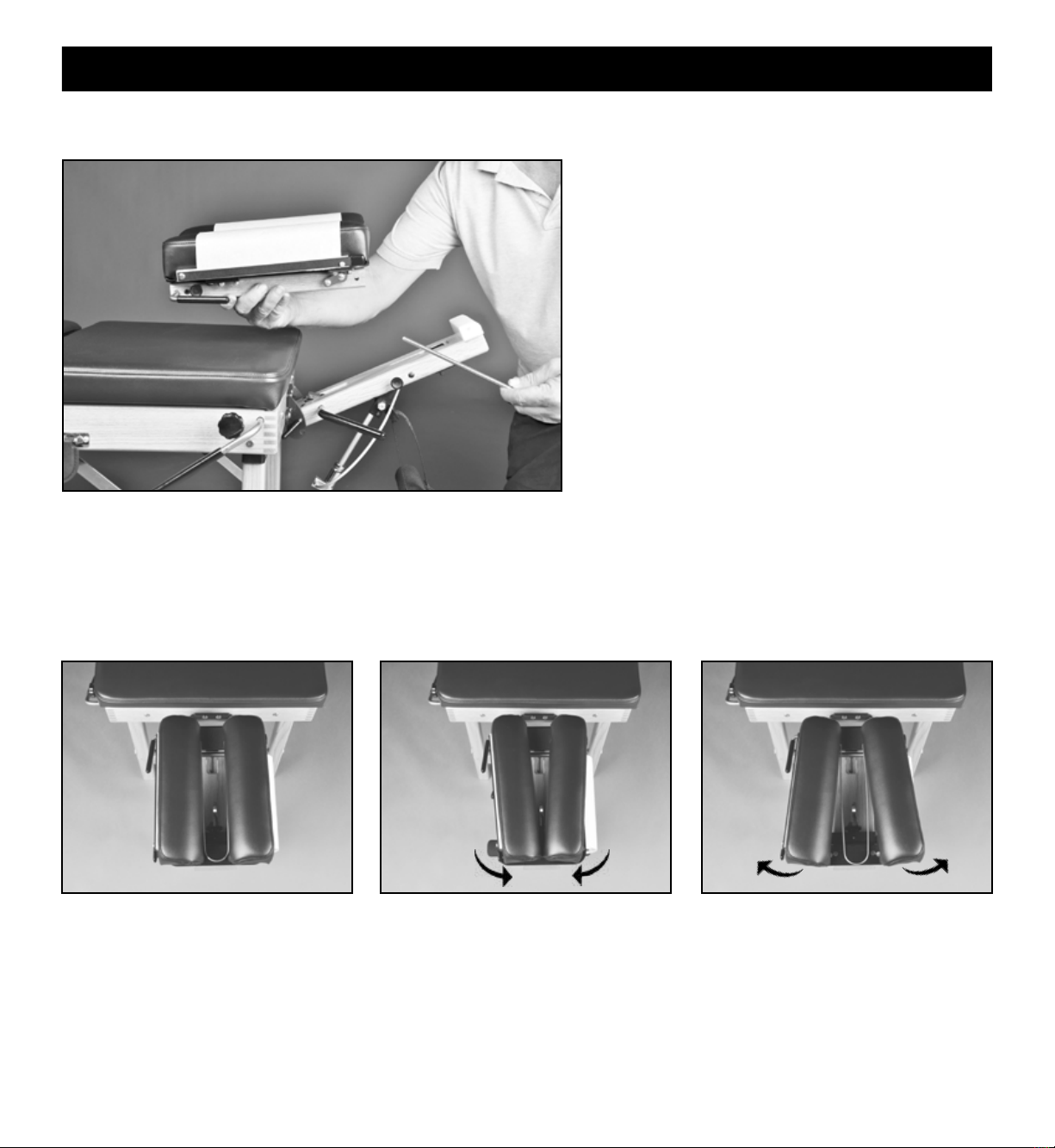
The Tour headpiece can easily be detached and used as a
portable headpiece for cervical adjusting. Simply lift the
back end of the headpiece until the T-bar disengages from
the locking link. Snap the T-bar into the receiver clip on
the underside of the headpiece for storage. Remove the
pivot pin from the front of the headpiece. Place the head-
piece on a stable surface. You can use the straight drop
and forward motion drops. Please note that it will not raise
up/down or ex/extend when not mounted to the table.
Neutral position. Narrower position for smaller faces
(eg children).
Wider position takes pressure off of
the patient's eyes.
The headpiece cushions are adjustable in width for patient comfort. Firmly pull up on the front end of each headpiece cushion and
move in (one or two notches) or out (one or two notches) to the desired position. Secure cushions by engaging locating pins into
notches provided.
Headpiece Operation 11
Note: A stabilization base for the portable headpiece is
available from Thuli Tables to distribute the drop forces
over a broader surface.
12
DROP OPERATION AND TENSION SETTING
1. Advise your patient prior to setting the tension.
2. With the patient on the table, cock the drop section with an upward motion of the cocking lever. There must be sufcient
tension on the drop to hold the patient's head or body weight.
3. Decrease the tension control knob by turning it counter-clockwise until the section drops.
4. Increase the tension by turning the tension control knob clockwise 3-4 half turns. As a general rule, the drop is now
set for the patient's weight, which may vary according to the practitioner's preference.
STRAIGHT DROP FORWARD MOTION DROP
Knob pulled out BEFORE cocking
Headpiece & Table Operation 12
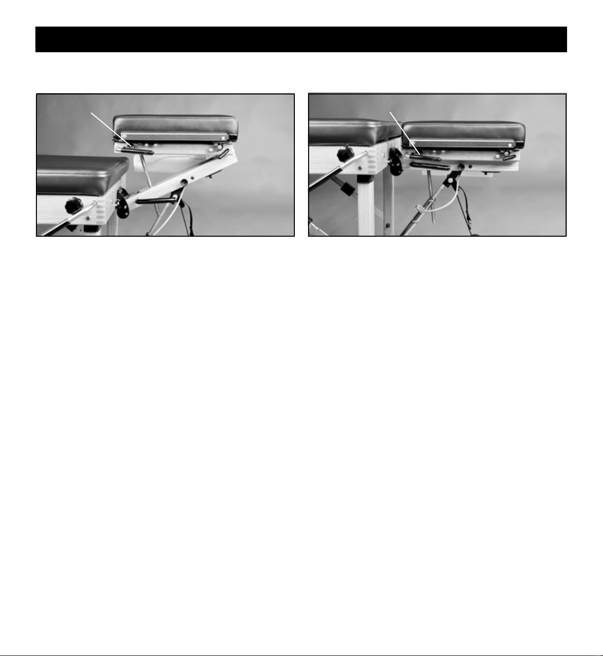
MAXIMIZING FACIAL COMFORT
For patients sensitive to pressure on the eyes, slightly raise the
back end of the headpiece. This will take pressure off of the
eyes, supporting the weight of the head at the mandible and
zygomatic arches. This maneuver, in combination with slight
exing of the headpiece, will provide optimal facial comfort for
some patients.
Knob pushed in BEFORE cocking
The drops on the headpiece and table have adjustable tension and cock with an upward movement of the cocking lever.
Following is a general guideline for setting the tension.
PRIOR to cocking the headpiece, set for straight drop by pulling
out the headpiece straight drop/forward motion knob until you
feel it is “set” into position. This will be just short of coming
into contact with the cocking bar. If you pull the knob out too
far, simply push it back in.
PRIOR to cocking the headpiece, set for forward motion drop
by pushing in the headpiece straight drop/forward motion knob.
Cock the headpiece with an upward motion on the headpiece cocking lever.
Please note: Be sure to change the headpiece drop function
before cocking the headpiece to prevent an ineffective drop and
damage to the drop mechanism.
Set the desired tension by turning the tension control knob clockwise (increasing tension) or counterclockwise (decreasing tension).
WEIGHTS FOR BACK LEGS
Place weights on the crosspiece of the back legs for counterbalance.

13
Cervical palpation and adjusting (shown on Tour) Anterior thoracic adjusting (shown on Tour)
THORACIC SLANT SECTION
When using the thoracic drop, the patient should be positioned
sufciently forward with arms outstretched and wrists supported
by the adjustable Prone Arm Rest. This will insure that the pa-
tient's arm will not be pinched between the thoracic section and the
table frame.
THORACIC DROP
Proper prone positioning on the pelvic drop section should have the
patient's anterior superior iliac spine (ASIS) at the juncture of the
pelvic and thoracic sections.
Table Operation 13
If you haven't already done so, release the thoracic section by
unfastening the Velcro on the underside of the table.
Note: Release the thoracic section prior to raising or using the drop.
PELVIC DROP
Swing down the metal slant bar and engage the ends into the holes
in the leg blocks.

14
Side posture support of the patient's head for lumbo-pelvic
adjusting or toggle recoil adjusting.
SIDE POSTURE POSITIONING
Table Operation 14
ANKLE REST EXTENSION
The ankle rest can be extended up to 8" and locked into
position by tightening the tension knob on the side of the
table. Shorter patients can drop their feet into the recess
created by the extended ankle rest.

15
1. Return the ankle rest extension, drop sections and headpiece to their neutral positions.
2. Tip the table onto its cushions.
3. Fold the back legs down into the table. Be sure to slide the black brace locks completely down to where the braces are riveted to
the table frame.
4. Secure the thoracic section in place with the Velcro closure.
5. Remove the remote control lever, utilizing the nger slot provided.
6. Remove the headpiece piston pin from the side of the headpiece to disconnect
the exion/extension piston from the headpiece base block.
7. Retract the piston rod completely into its cylinder by operating the remote
control lever with one hand while pushing the rod in with the other. (photo)
8. Store the headpiece piston pin in the hole from which it was removed.
9. Fold the front legs into their storage position.
10. Swing the prone arm rest, along with the piston, all the way into the table,
tucking the remote lever with attached cable under the two metal bars of the
prone arm rest. Engage piston into hole in frame.
11. Disengage the T-bar from the headpiece base block by holding the headpiece
side rail down with one hand while lifting the base block with the other.
Store the shaft of the T-bar in the clip on the inside headpiece strap. Fold the
base block of the headpiece back down over the T-bar.
WHEN FOLDING THE TABLE, REVERSE THE SEQUENCE OF TABLE SET UP.
Table Fold-Down 15
12. Fold the headpiece into its storage position and secure in place with the Velcro strap.
13. Loosen the ankle rest lock-down knob and remove the ankle rest. Slightly lift up on the front legs and insert the ankle rest rods
into their storage position.
Folding
Support Brace Remote Control
Paper
Headpiece
Ankle Rest
Extension
Thoracic Cocking Bar
Thoracic Cocking Bar
Thoracic Cocking Bar
Thoracic Cocking Bar
Pelvic Cocking Bar
Tear-Off Bar
Hanger
16 Accessories 16
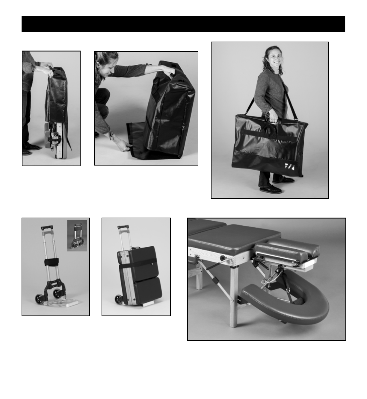
PROTECTIVE COVER
Provides excellent protection when traveling by car. With
the folded table in its upright position, place the cover over
the top of the table. Lean the table forward and tuck the ap
under the table. Lean the table back and pull the ap from
under the table and secure with Velcro.
PULL CART
This strong, lightweight folding Pull Cart is great for transporting
the Tour. With large 5" rubber wheels, it easily negotiates
stairs, curbs and athetic elds. A velcroed strap secures the
table to the Pull Cart. For added convenience, it can be used
in conjunction with the Protective Cover or Airline Travel Case.
When folded, the Pull Cart ts inside the airline overhead
compartment. Photo shown with Tour portable table.
CRESCENT ARM REST
The Crescent Arm Rest provides additional forearm support in
the prone position and is easily adjustable in height. To attach,
simply slide both slotted ends of the bracket onto the rivets
located on the inside of the front legs and push down onto the
standard Prone Arm Rest. The Crescent Arm Rest will snap
into place. Can be added at anytime.
17 Accessories 17
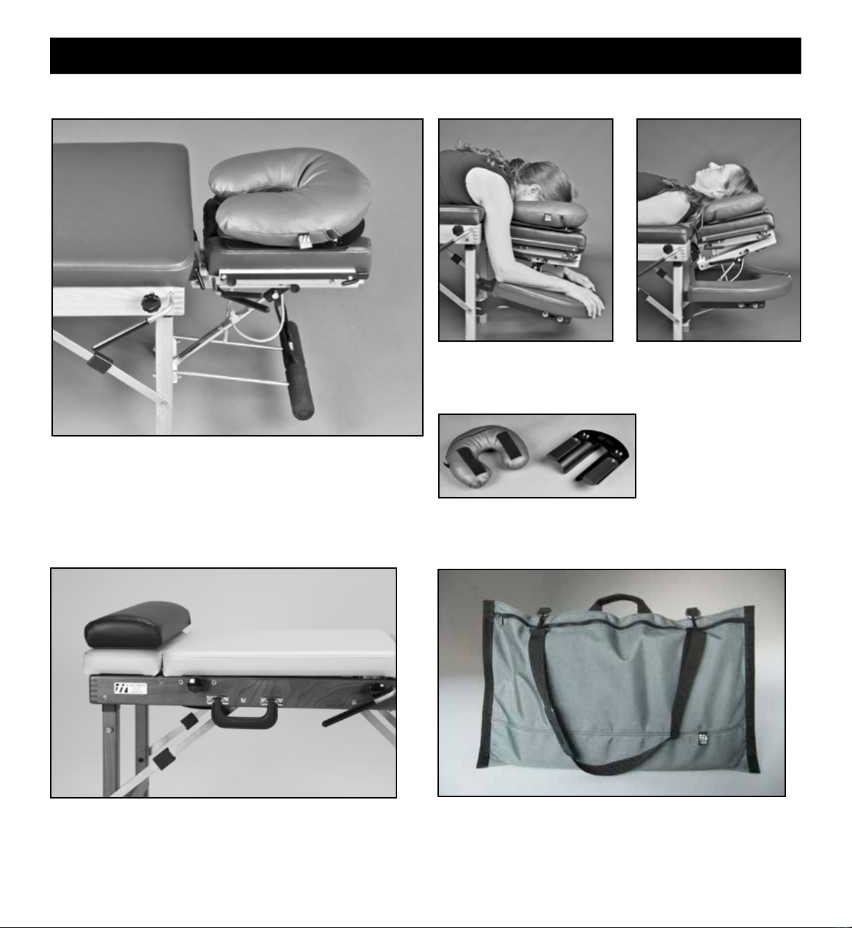
COMFORT PILLOW
Base
Pillow
The velcro on the underside
of the pillow secures it to
the base, allowing for width
adjustability.
Rotate the Comfort Pillow 180
degrees to provide cervical
support in the supine position.
The Comfort Pillow offers
massage quality facial comfort
in the prone position.
The base of the Comfort Pillow quickly inserts into place between
the headpiece cushions. The width of the opening is adjustable.
Use with Thuli tables or any other manufacturer’s table!
Comfort Pillow
Bolsters are 20" wide with a nonslip base. Choice of two
heights: 2.75" or 4.25". Use in prone position under ankles or in
supine position under knees to relax hamstrings.
BOLSTERS
2.75" x 20" Bolster
CARRYING BAG FOR ACCESSORIES
Carrying Bags are custom-sized to t the Crescent Arm Rest
or Comfort Pillow.

18
DROP MECHANISM LUBRICATION
Periodic lubrication of the drop mechanisms will insure smooth, crisp drops. We recommend that you use 3-IN-ONE oil after about
500 adjustments or once/month, whichever comes rst. If the drops have not been lubricated on a regular basis, it is recommend to rst
clean the plungers using WD-40. See instructions below.
CERVICAL DROPS THORACIC & PELVIC DROPS
1. Elevate the headpiece (as shown) and cock the drop mechanism.
2. Apply 3-IN-ONE into the hole of the drop mechanism
housing. Allow a few minutes for the lubricant to penetrate
the mechanism before using the headpiece drops.
1. Cock each drop section and then tip the table onto its side
with the cocking handles. This will expose the lubrication
hole in the drop mechanism housing (located on the opposite
side of the cocking handles).
2. Apply 3-IN-ONE oil into this hole. Allow a few minutes
for the lubricant to penetrate the mechanism before using
the drop.
UPHOLSTERY
Normal day to day soil on the vinyl upholstery can be removed
with neutral soap and warm water followed by a thorough water
rinse. Avoid harsh detergents and powdered abrasives. Areas
coming in contact with hair, body oils or perspiration should be
washed frequently. Remove stains immediately to prevent the
possibility of them becoming permanent. In the event of damage,
pre-sewn replacement upholstery is available from Thuli Tables.
Care & Maintenance 18
If the drops have not been lubricated on a regular basis:
Routine lubrication:
1. First clean the plunger from accumulated dust and debris
by applying WD-40 (as described above) and then drop the
headpiece several times.
2. Apply 3-IN-ONE oil to lubricate the drops (as described
above).
Routine lubrication:
If the drops have not been lubricated on a regular basis:
1. First clean the plungers from accumulated dust and debris by
applying WD-40 (as described above) and then drop the
section several times.
2. Apply 3-IN-ONE oil to lubricate the drops (as described above).
TENSION CONTROL ADJUSTMENT
The set screw on the bottom of the thoracic, pelvic and caudal
drop mechanisms can be adjusted (using an 1/8” allen wrench)
so that the tension control rod has more or less resistance.
See photo above.
Increase resistance: Turn the set screw clockwise. This is
helpful if the tension control rod is “backing out" while using
the drop.
Decrease resistance: Turn the set screw counter-clockwise.
Set Screw
Office Art
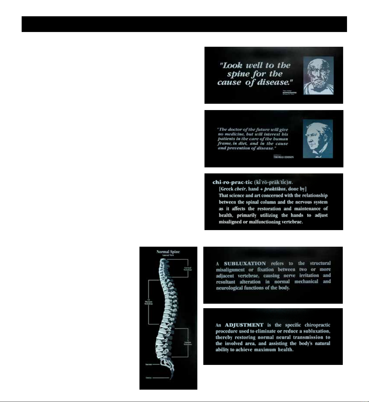
EDUCATION PLAQUES (set of three)
QUOTATION PLAQUES (set of three)
Recognizing the need for distinctive, contemporary graphics for
chiropractic ofces and reception areas, Thuli Tables has com-
missioned two ne sets of plaques. Unmatched in visual appeal
and content, these plaques are perfect for your consultation and
adjusting rooms. They will assist your patients in understanding
the essential principles of chiropractic.
Silkscreened on black laminate, each piece is 9” x 22” x 3/4”.
VERY MODERN,
VERY SOPHISTICATED
19

20
Elevation Tables
Tour Portable
300 Stationary
Sport Portable
500 Stationary
Portable Drops
Lumbo-Pelvic Drop
Extremity Drop
Speeder Board
Portable
Headpiece
www.thulitables.com youtube.com/thulitables
Table of contents
Other Thuli Tables Medical Equipment manuals


