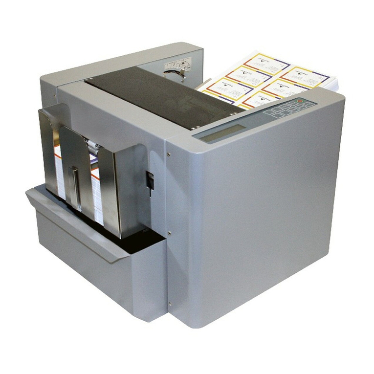
Duplo DocuCutter DPC-400 User manual

1
DocuCutter DPC-400
Digital Die Cutter
Operation Manual
Revision: 111519AP

2
CONTENTS
1. User Notes
………………………………………………………………………………
3-6
2. Frame and Parts
…………………………………………………………………………
7
2-1 List of Parts (1)
………………………………………………………………………
7
2-2 CUTTER FRAME-
………………………………………………………………………
8
2-3 CUTTER FRAME-
………………………………………………………………………
8
2-4 CUTTER FRAME-
………………………………………………………………………
8
2-5 Sheets Pre-load Platform
…………………
…………………………………………
9
3. Operation guide
…………………………………
………………………………………
9
3-1 Installation
…………………………………………………………………………
10
3-2 Cutting Tools Installation
……………………………………………………………
12
3-3 Turn on/off
…………………………………………………………………………
13
3-4 Cut Depth and Tools Selection Setting
………………………………………………
14
3-5 Offset for Creasing Wheel Tool
……………………………………………………
15
3-6 Data Transmission Settings
…………………………………………………………
16
3-7 Camera Settings
………………………………………………………………………
17-18
4. SOFTWARE
…………………………………………………………………………
……
19-22
4-1 Software Installation
…………………………………………………………………
19
4-2 Print Setup
……………………………………………………………………………
20-21
4-3 Print Files
……………………………………………………………………………
22-24
4-4 Camera Registration
…………………………………………………………………
25-26
5. Function Setup
……………………………………………………………………………
27-33
Cutter reset interface
………………………………………………………………………
27
5-1 TEST
…………………………………………………………………………………
27
5-2 Setup
…………………………………………………………………………………
28-32

3
5-3 Suction
…………………………………………………………………………………
33
5-4 Reset
……………………………………………………………………………………
33
5-5 Enter
……………………………………………………………………………………
33
5-6 Communication
……………………………………………………………………
…
33
6. Q & A of Alarms
……………………………………………………………………………
34
7. Maintenance
……………………………………………………………………………
35
8. Specification
……………………………………………………………………………
36
Warranty
……………………………………………………
………………………………
37

4
1. User Notes
1>SAFETY RULES
After receiving the machine, if end users require any further modification or change of one part or
several parts of the machines, they are obligated to advise the machines back to the manufacture for
this treatment.
We do not have any legal responsibilities if the breakdown of the machines or operator’s injuries is
caused by the importer’s modifications or changes to one part or several parts of the machines
performed by end users.
The machine has many safety features which make it a safe machine to operate. Regardless of your
experience, safety instructions must be read carefully, completely understood, and applied to your
daily work habits. If you do not understand or are confused by certain safety instructions presented in
this manual, discuss them with your supervisor. Machine setup, cleanup, and maintenance operation
will vary. Therefore, it is essential all employees to practice safe work habits. SAFE WORK HABITS
PREVENT INJURIES. The main rule to follow is to ALWAYS make sure the main drive is STOPPED and
LOCKEDOUT when performing setup, cleanup, and maintenance operations.
The safety precautions in this manual provide guidelines for the protection and for that of fellow
workers.
1.1 Precautions
Before any maintenance is performed on the machine, switch off all sources of energy, electrical, do
not operate the equipment when panels and safety guards are not in place. Failure to observe this
warning could result in personal injury.
1.2 Avoid Accidents
Most accidents are caused by the failure of some individual to follow simple and fundamental safety
rules and precautions. For this reason, most accidents can be prevented by recognizing the real cause
and doing something about it before the accident occurs. With any machinery, a careful and trained
operator is the best insurance against an accident.

5
1.3 Safety Issues & General Safety Rules
DO DO NOT
1. Read and understand this manual before
attempting to operate or service the
machine.
1. Do not attempt to operate or service the machine
without reading and understanding this manual.
2. Be familiar with the machine safety rules
and practices.
2. Do not remove the safety devices. Including
electrical interlocks.
3. In case of an accident while the machine, is
running press the emergency stop button to
stop the machine.
3. Do not start the machine unless you are sure there is
no danger to you or your fellow workers.
4. Warn others of an intended action that may
endanger them.
4. Do not clean or lubricate moving parts of a machine
that is running.
5. Perform lubrication and oiling of the
machine only when it is stopped.
5. Do not unauthorized persons to operate the
machinery.
6. Verify that all guards are installed before
operating the machine.
6. Do not wear jewelry, neckties, or loose clothing near
moving machine.
7. When working on electrical equipment,
power must be shut off to all circuits before
any work is attempted. Individual switches
must be opened, and the equipment circuits
tested to make sure there is no power.
7. Do not place tools on a machine that is running.
8. Be sure all operators are aware of all areas
and operations that require extra safety
measures.
8. Do not reach into the machine to make adjust while
it is running.
9. Keep the floor clean around the machine. 9. Do not use a rag on rotating rollers. Do not use any
cleaning cloths or paper on rotating rollers
10. Keep aisles and walkways clear. 10. Do not have anything (coins, pens, etc.) in your
pockets.
11. Return tools to their proper places after
use.
11. Do not allow horseplay in the work area.

6
2.INTRODUCTION
2.1What is the DocuCutter DPC-400 Does
DocuCutter DPC-400 is design for cutting and creasing to the digital printed material, such as
labels, cards and packing cartons on demand.
2.2 Symbol Description
This manual’s symbols correspond to the specific area on the machine. These safety warnings are
placed to protect both the user and anyone within the machine’s vicinity. These are also
positioned to ensure that the machine is operated properly and safely. Each symbol and its
meanings are explained below.
Keep your hands away. Something heavy might fall
from above.
Be careful of high voltage or the risk of electric shock.
Power Switch
Be careful of rollers and keep your hands away.
CAUTION
Be careful of UV light. Do not look directly into the
beam or view directly with any optical instruments.
Be careful of touching the blades. The blades are
extremely sharp which could result in a serious injury
when coming into play with hands or other parts of
the body

7
2.3 Name Plate
2.4 USAGE PRECAUTIONS
2.4.1 Before Operation
a. Understand emergency stop button and main power location. In addition, normal
operation must be confirmed.
b. Tools and sundries should not be put on the machine.
c. No obstacles should surround or be placed on top of the machine.
d. Personnel staying in risk areas are forbidden.
e. Do not place any liquids on top of the machine
2.4.2 During Operation
a. Do not open any doors or guards.
b. No personnel in risk areas.
c. No maintenance and repair.
2.5.3 Maintenance
a. Power must be turned off before leaving the machine.
b. The location of each limited switch is identified.
c. Power must be turned off when personnel enter risk areas.
d. Check all buttons and switches are in the normal position.
e. Switches must be turned off before opening any door/guards.

8
2.5.4 Others
a. Damaging all external and internal panels and controls is forbidden.
b. Do not cover each button and switch.
c. The machine should be kept clean at all time.
d. Warning signs and tags on the machine should not be removed or destroyed. If you
have any questions, please contact your agent or dealer.
2. Frame and Parts
2-1 List of Parts (1)
Caution:
Check items listed above before installation
The tools and blades listed above is a standard offer, tools and blades vary based on specific
offers. Please check with your supplier if you have any questions.
The photos above are for reference only. The tools and blades listed above subject to
change without notice.
Name Photo Qty’ Name Photo Qty’
Ethernet cable
10m Grounding
cable
1
Creasing
wheel
1 Power
supply cable
3m
Straight
screwdriver 1 Dongle
1
Picture knife
1 screw
dozens
Allen wrench 1 Pipe clamp 5

9
2-2 CUTTER FRAME-
2-3 CUTTER FRAME
2-4 CUTTER FRAME-

10
2-5 Sheets Pre-load Platform

11
3. Operation guide
3-1 Installation
Key Components
1. Feeder
2. Conveyor Belt
3. Cutting Head
4. Control Panel
5. Stacking Tray
6. Electric box
1
2
3
4
5
6

12
➊Installation Requirement
a. Long arm forklift or crane at less 1 tons
b. It requires a proper area for placing the cutter, about 79CM*230CM, the floor
should be as flat as possible.
c. It requires a clean room without EMI or static interference and operates under
circumstance with humidity of 50-80%Rh and 20-25℃.
d. Compressed air supply: 4-8kg/cm^2, no less than 1.5HP.
➋Placement
a. Extend feet of the cutter (to the height that higher than the wheels) with
adjustable wrench after place the cutter in position
b. Level the system is very important
c. Stacking Tray Install and adjust proper size for paper

13
➌Compressed Air Installation
1. Incoming Air Adjuster No.1 - Adjust the air pressure to 0.3-0.6Mpa,
2. Adjust valve No. 2 to 0.2-0.3Mpa.
No.1
No.2
Input

14
3-2 Cutting Tools Installation
Select the type of tool you need.
Tool Name J201 J202 J205 J206 J208
Paper Type Paper/Card Paper/Card Card Stickers Sticker
Paper Thickness
(gsm)
120-300gsm 150-400gsm 400-1kg Sticker or less
than 300gsm
➊
Blade Installation Procedures
a. Unscrew the cap of the blade holder:
b. Put a blade into the holder and push it to the end:
c. Put the cap back and leave about 2mm of the tip of the blade out of the cap. Make
sure the tip can rotate freely in the holder:
d. Put the holder to the cutting head of the cutter. Make sure the holder is put in
posi4tion. Fasten the holder by a flat screwdriver

15
Creasing wheel installation
1&2 are the Allen screws, those two screws use for fix the crease wheel .Number 3 is the screw
which use for pull the wheel holder and adjust the center of wheel blade .
a. loosen1&2 then loosen 3
b. Push down that wheel blade holder
c. Change new wheel blade (4)
(4)
Note: The wheel can be installed off of center. Please test the Wheel Offset Calibration on a blank
sheet see if the wheel is installed correctly.

16
3-3 Turn on/off
Turn On the cutter
➊Connect power supply and turn on the main switch ,clockwise rotate to release emergency stop button.
➋Press Green Starting Button ..
The cutter starts initializing....
The cut system starts in 10 seconds and displays welcome page:
➌Click
Duplo USA
and the cutter starts to reset.
Verify no people within electric appliances area before turns on main power supply.
Verify all emergency stops are closed before close the breaker.
➍Turn off the cutter
Press emergency stop down if you want to turn off the cutter. Switch off the main power supply
Breaker.

17
Main Screen
To enter the TEST menu
To enter the Setup menu
To turn the pump ON or OFF
To reset the machine to the home position
To resume the job
TEST SCREEN

18
Test Motions Head Motion Depth Origin
Knife Action UP Arrow
Knife Depth: Adjusts the knife depth.
The higher the number the lower the
unit goes.
Back Origin: Head
Unit goes Feeder
postion
Knife1 Action DOWN Arrow
Knife1 Depth: Adjusts the Knife1
depth. The higher the number the
lower the unit goes.
Front Origin: Head
unit goes to Home
postion.
Wheel Action LEFT Arrow
Wheel Depth: Adjusts the Wheel
depth. The higher the number the
lower the unit goes.
Temp Origin: Sets
temporary home
postion.
Sucker Action RIGHT Arrow Test Speed: Speed of the Head Unit
Manual Feed: feeds
one sheet
Pump ON/OFF Origin
SETUP SCREEN
TOOLS TAB

19
TOOL SELECT SPEED ACC
SP1 to SP8: Define the
tool used
- None
-Knife
-Knife1
-Wheel
Knife1 Speed: Maximum speed it can
reach
500 (default)
Knife1 Acc: Acceleration speed of
Knife1
3500 (default)
Cut Speed: Maximum speed of Knife
tool
600 (default)
Cut Accel: Acceleration speed of Knife
3500 (default)
Move Speed: Speed of the Head Unit
in up position
700 (default)
Move Accel: Acceleration speed of
Head Unit
3500 (default)
Cut Down Speed: Knife and Knife1 up
and down speed
100 (default)
Cut Down Accel: Acceleration speed
Up and down motion for Knife and
Knife1 tool
3500(default)
Bending Speed: Control the speed
when making curves
150 (default)
WHEEL TOOL SETTING

20
WHEEL TOOL SETTING DELAY (Not Used) ANGLE
Wheel Down Speed: Maximum
down speed of wheel
700(default)
Lifter1 Delay: 0 Pen Dec Angle: 0.0
Wheel Speed: Maximum speed
of wheel
700 (default)
Knives1 Delay: 0 Pen Stop Angle: 20.0
Wheel Acc: Acceleration Speed
of Wheel
2500 (default)
Cut Up: 0 Cut Dec Angle: 0.0
Wheel down Accel: Acceleration
speed of wheel
2000 (default)
Cut Down: 0 Cut Stop Angle: 20.0
Wheel Up: 0 Raise Angle: 30.0
Wheel Down: 0
Table of contents
Other Duplo Cutter manuals

Duplo
Duplo DocuCutter CC-330 Quick start guide

Duplo
Duplo DC-646 User manual

Duplo
Duplo DC-535 User manual

Duplo
Duplo DocuCutter CC-228 Building instructions
Duplo
Duplo DocuCutter DC-545 Installation guide

Duplo
Duplo DocuCutter CC-229 Building instructions

Duplo
Duplo DC-618 User manual

Duplo
Duplo DC-618 User manual

Duplo
Duplo DC-646 User manual
Duplo
Duplo DocuCutter CC-330 Building instructions