TLM PRIME 400 Manual
Traslation of Original Instruction - Edition 01 of 27/01/2017
Via Venezia, 34/N-O-P - 10088 - Volpiano (Torino)
Tel. 011.9881307 –Fax. 011.9881084
www.tlmpack.com
USE AND MAINTENANCE
HANDBOOK
PRIME 400 PACKAGING MACHINE

Use and Maintenance Handbook –Prime 400 Packaging Machine
Page 2 of 71
TABLE OF CONTENTS
1. PREFACE........................................................................................................... 4
2. WARNINGS AND GUARANTEES...................................................................... 5
3. SPARE SERVICES ............................................................................................ 6
4. INTENDED USE................................................................................................. 6
5. NON PERMITTED CONDITIONS OF USE ........................................................ 7
6. IDENTIFICATION PLATE................................................................................... 7
7. DESCRIPTION AND TECHNICAL SPECIFICATIONS ...................................... 8
7.1 Loading floor........................................................................................................10
7.2 Adjustable conveyor ............................................................................................10
7.3 Unwinding group..................................................................................................11
7.4 Perforator ............................................................................................................11
7.5 Welding group.....................................................................................................12
7.6 Discharge chute...................................................................................................13
7.7 Pneumatic system ...............................................................................................14
7.8 Electrical System.................................................................................................15
7.9 Technical specifications.......................................................................................16
8. TRANSPORT AND HANDLING ....................................................................... 17
9. INSTALLATION................................................................................................ 19
10. SAFETY............................................................................................................ 20
10.1 Particular recommendations................................................................................21
10.2 Intended, unintended and improper uses.............................................................23
10.2.1 Contraindication and danger of the unexpected uses..........................................25
10.3 Safety..................................................................................................................26
10.3.1 Introduction..........................................................................................................26
10.3.2 Danger of cutting and crushing............................................................................26
10.3.3 Stability loss.........................................................................................................26
10.3.4 Electrical hazards ................................................................................................27
10.3.5 Fire hazard ..........................................................................................................27
10.3.6 Danger of cutting.................................................................................................27
10.3.7 Thermic danger ...................................................................................................28
10.3.9 Danger due to the machine handling...................................................................29
10.4 Main protections..................................................................................................30
10.4.1 Mobile guards, access door to the internal components......................................31
10.4.2 Permanent guards...............................................................................................31
10.4.3 Pneumatics guards..............................................................................................32
10.4.4 Electrical protections............................................................................................33
10.4.5 Plate and indications............................................................................................35
10.5 Reference standards ...........................................................................................36
10.6 Risk analysis and the safety measures adopted..................................................37
10.6.1 Functioning in production.....................................................................................38
10.6.2 Functioning during fine tuning / Maintenance ......................................................43
10.7 Noise...................................................................................................................44
10.8 Electromagnetic compatibility ..............................................................................45

Use and Maintenance Handbook –Prime 400 Packaging Machine
Page 3 of 71
11. INSTRUCTIONS FOR USE.............................................................................. 46
11.1 Operator..............................................................................................................46
11.2 Safety regulations for a proper functioning ..........................................................47
11.3 Control panel.......................................................................................................48
11.4 Operator panel description ..................................................................................49
11.4.1 Main menu page..................................................................................................49
11.4.2 Jog and homing page..........................................................................................50
11.4.3 Piece counter page..............................................................................................51
11.4.4 Mark setup page..................................................................................................52
11.4.5 Bags length setup page.......................................................................................53
11.4.6 Recipe page ........................................................................................................54
11.4.7 Machine settings page.........................................................................................56
11.4.8 Jaws page...........................................................................................................56
11.4.9 Temperature page...............................................................................................57
11.5 Working phases...................................................................................................58
11.5.1 Functioning cycle.................................................................................................58
11.5.2 Machine switch-off...............................................................................................59
11.5.3 Reset after emergency stop.................................................................................59
11.5.4 Mounting the bobbin, film drawing-in and centring...............................................60
11.5.5 Regulating mark reading .....................................................................................60
11.5.6 Regulating the length of the bag..........................................................................60
11.5.7 Regulating Loading conveyor ..............................................................................61
11.5.8 Regulating the cut................................................................................................61
12. MAINTENANCE................................................................................................ 62
12.1 Program maintenance .........................................................................................64
12.1.1 Daily maintenance...............................................................................................64
12.1.2 Semi-annual maintenance...................................................................................64
12.1.3 Annual maintenance............................................................................................64
12.2 Extraordinary maintenance..................................................................................65
12.2.1 Jaws resistance replacement...............................................................................65
12.2.2 Jaws proximity sensor replacement.....................................................................65
12.2.3 Jaws sonda probe replacement...........................................................................66
12.2.4 Roller resistance replacement and adjustment....................................................66
12.3 Maintenance on the Pneumatic System...............................................................67
12.3.1 Filter and pressure regulator................................................................................67
12.3.2 Command valves with a pneumatical actuation direction.....................................68
12.3.3 Flow regulator......................................................................................................68
12.3.4 Actuators.............................................................................................................69
12.3.5 Calibration procedure of the flow regulators ........................................................69
13. DECOMMISSIONING AND DEMOLITION....................................................... 70
14. APPENDICES................................................................................................... 71

Use and Maintenance Handbook –Prime 400 Packaging Machine
Page 4 of 71
1. PREFACE
The purpose of the information in this “Use and Maintenance Manual” is:
To show the use of the machine envisaged by the design assumptions.
Provide the instructions for transport, installation, assembly, fine tuning and
use to the operators and the maintenance personnel...
Facilitating the ordering of any spares or materials subject to wear and tear.
Provide indications of the risks involved in carrying out the tasks assigned.
Enable the personnel who use the machine, to operate in safety and
guarantee perfect efficiency throughout its life.
This is to be considered an integral part of the machine and must be “kept” until
it’s finally dismantled.
Furthermore, the content of this manual does not contemplate any risks that may
derive from coupling with other machines.
As a rule it must always be made available for consultation and duly preserved in
a dry, protected place away from the rays of the sun and be known to all the
users (machine operators and maintenance personnel).
TLM PACKAGING reserves the right to make modifications or updates to this
manual at any time and without warning.
The machine to which this manual refers complies with the following Directives:
“Machine Directives” 2006/42/ EC
“Electromagnetic Compatibility 2014/30/UE
and it also takes into account indications deriving from consulting the harmonised
UNI and CEI standards, and Guide to application of the Machinery Directive
2006/42/EC 2nd Edition –June 2010. As defined by the directive, this document
has been drawn up in Italian and has, if necessary been translated into a
community language that has to be the language of the user.
This document will be accompanied by drawings and schematics necessary for
commissioning, maintenance, checking and inspection and, if necessary, repair.

Use and Maintenance Handbook –Prime 400 Packaging Machine
Page 5 of 71
2. WARNINGS AND GUARANTEES
TLM PACKAGING, produces and designs its machines in the most complete respect
of the current safety regulations, with the purpose of ensuring the user the maximum
guarantee in carrying out all the operations envisaged and permitted, together with
the minimum possibility of incidents due to any residual risks. Even after
commissioning TLM PACKAGING shall be able to make modifications to the
machine, modifications that in its unimpeachable judgement represent improvements
for the functioning. TLM PACKAGING ensures that the machine contains no defects
in the materials or the workmanship for a period of 24 months from the date of the
purchaser’s final test, always without prejudice to different contractual conditions.
During this period, TLM PACKAGING undertakes to repair or to substitute, in the time
necessary, those parts that are damaged and/or contain defects at the origin
providing the purchaser notifies TLM PACKAGING of the fact by means of registered
letter with a notice of receipt slip, within seven days of the discovery. The above
conditions are without prejudice to different contractual conditions. In any event all
further obligation and/or indemnity on the part of TLM PACKAGING is excluded. The
warranty referred to above (or the contractual warranty) is only applied if the
purchaser has complied with the regulations in the contract and only if the installation
and the subsequent use of the system has been carried out by the purchaser in
compliance with the instructions contained in this instruction manual. The warranty
excludes all or any liability for direct or indirect injury to persons or damage to
property deriving from the inadequate or improper use or maintenance of the above
mentioned machine. This warranty does not extend to repaired or replaced parts.
Also excluded from the warranty are all the parts that because of their specific use
are subject to wear. In conclusion transport costs, inspections, dismantling and
reassembly due to the intervention of a TLM PACKAGING technician are excluded
from the warranty and will be charged to the purchaser if the flaws and/or defects
found are not covered by this warranty, the above being without prejudice to different
contractual conditions. The warranty automatically becomes null and void in the case
of repairs, modifications or removals or replacement of components aren’t previously
communicated to or agreed and approved by TLM PACKAGING.
The machine must not be used or any work must not carried out, thereon this
collection of documents as not been carefully read and fully understood.

Use and Maintenance Handbook –Prime 400 Packaging Machine
Page 6 of 71
TLM PACKAGING cannot be held responsible for failures, problems or accident
due to non-compliance with this prohibition. Tampering with or altering the
machines and the installed devices, even partially, is prohibited.
The machine is designed in order to package products from various sectors,
including food sector, into specifics bags.
Before proceeding to the product changeover due to the change belongings field,
contact the TLM to get indications.
3. SPARE SERVICES
It may be possible over time that the above mentioned machine may need the
replacement of components, for this purpose the purchaser may order the
components to be replaced. Said customer (purchaser) is obliged to always
purchase O.E.M. spares. For any request of spare parts, it is always necessary to
specify the serial number of the machine that the spare part is referring to, as
indicated on the identification plates. As regards components, please refer to the
attached layout (APPENDIX 4).
4. INTENDED USE
CAUTION
THE MACHINE IS SUPPLIED WITH PERIMETRIC PROTECTIONS AND SAFETY DEVICES,
IN ORDER TO PACKAGE PRODUCTS FROM VARIOUS SECTORS, INCLUDING FOOD
SECTOR, INTO SPECIFICS BAGS.
THE MACHINE, AS PREVISTED BY ITS INTENDED USE, IS REALIZED TO RUN WITH
THE PROTECTIONS AND THE SAFETY DEVICES ACTIVED AND INSTALLED.
TO THE USER: IT’S ABSOLUTELY PROHIBITED ALTERING OR TAMPERING THE
MACHINE, EVEN PARTIALLY, IF NOT AGREED UPON BY THE CONSTRUCTOR; IN
CASE OF NON-COMPLIANCE WITH THIS RULE, THE CONSTRUCTOR CANNOT BE HELD
RESPONSIBLE
Use and Maintenance Handbook –Prime 400 Packaging Machine
Page 7 of 71
5. NON PERMITTED CONDITIONS OF USE
The Constructor declines all responsibility in the following cases:
Use of the machine different than the one provided for.
Improper use of the machine or personnel who are not properly trained.
Incorrect installation.
Defective power supply.
Serious shortcomings with regard to the required maintenance.
Unauthorised work on the machine.
Use of non OEM spares or spares that are not specific to the model.
Total or partial non-compliance with instructions.
Dimensional or geometric inaccuracies of parts to be worked.
Work material is not loaded properly.
Work material other than the one permitted.
Exceptional events.
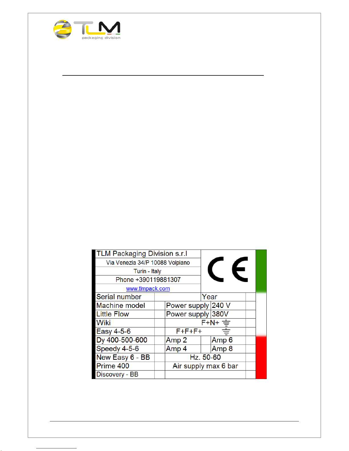
6. IDENTIFICATION PLATE
The following identification plate is attached to the machine:
Use and Maintenance Handbook –Prime 400 Packaging Machine
Page 8 of 71
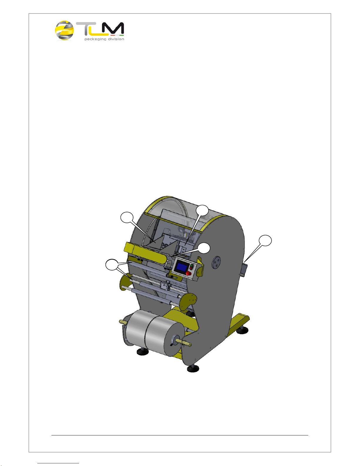
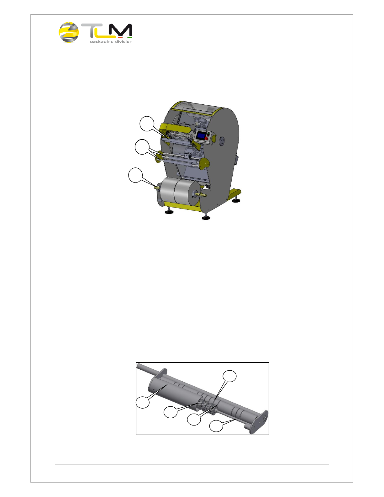
7. DESCRIPTION AND TECHNICAL SPECIFICATIONS
The machine is designed to package products into specifics bags. Loading
operation of the products to be packaged is performed manually by the operator.
The discharge chute conveys packaged products in an appropriate container.
The packaging machine is composed of :
A. Loading floor;
B. Adjustable conveyor;
C. Unwinding group;
D. Welding group;
E. Discharge chute;
D
C
E
A
B
C

Use and Maintenance Handbook –Prime 400 Packaging Machine
Page 9 of 71
CAUTION
The machine has as final use purpose the productive aim described
above and so can only be used to reach such objective, following the
procedure and the indications brought back in this manual, remaining
moreover very closely to the brought back functional limits.
A different use of the machine and/or also the overcoming of an only one
limit, held the user responsible of eventual damages, failures, and
accident on things or persons, caused of its acts.
Its recommended to the user to adhere scrupulously on whats indicate in
this manual, in particular regarding the safety and the preventions of
accidents, and, in case of doubt, always consult the constructor before
acting.
Under no circumstances may the system and/or this manual be modified
or tampered with by people not delegated to do so by the manufacturer,
the manufacturer cannot be held responsible of any derived
responsabilities due to non compliance with this provision.
This machine must never be used in environment where there is
explosion risk.
Note: the machine, as previsted by its destination of use, is realized
to work with protections and safety devices activated and installed.
Use and Maintenance Handbook –Prime 400 Packaging Machine
Page 10 of 71
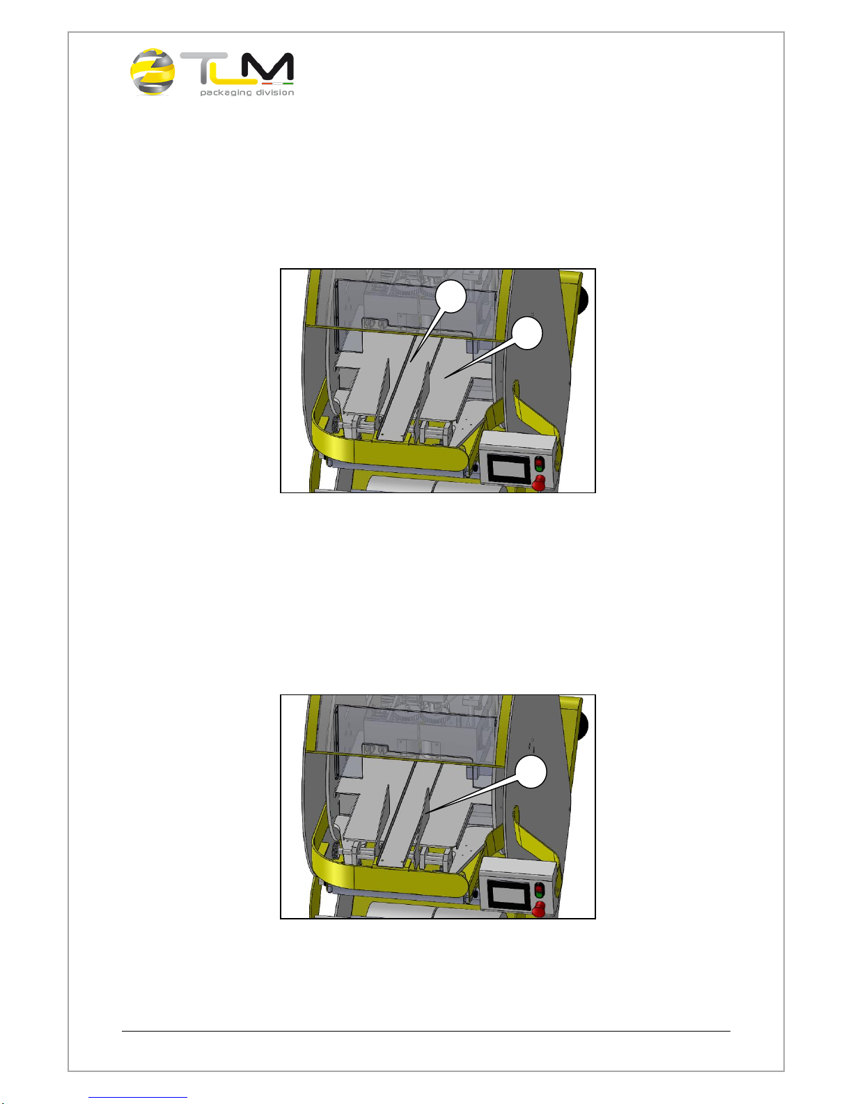
7.1 Loading floor
The loading floor (A) can be equipped with an optional tunnel wich allows to
maintain the alignment of the product while it reaches the packaging area. The
loading operation is performed manually by the operator.
7.2 Adjustable conveyor
The adjustable conveyor (C) is regulated according to the dimensions of the
product to be packed. Thanks to the adjustable conveyor, the packaging adheres
to the product while limiting the flexibility. The manufacturer’s technicians regulate
the conveyor during test run, the customer may change it a little.
A
C
B
Use and Maintenance Handbook –Prime 400 Packaging Machine
Page 11 of 71
7.3 Unwinding group
The unwinding group puts strain on the film and positions it into place. It is made
up of a shaft for the bobbin (A), some idler rollers (B) and a tensioning system(C).
7.4 Perforator
The perforator is an optional accessory. The machine can be equipped with a
single or multiple type perforator to realise microperforations on the film, so that
the packages have not air inside. The multiple perforator is purpose-built based
on the final customer’s need. The series of idler rollers equipped with needles to
perforate the film (A) are placed on a regulating shaft (B), and then blocked by a
threaded dowel (C). The series of idler rollers can be moved into specific
positions by the grooves on the contrast roller placed in opposition to the needles
(D). The grooves are realised in a position suitable with the type of packaging to
be realised on the machine. A protective casing is placed in the front part, to
avoid contact with the needles in rotation (E).
Example of multiple perforator
A
B
C
B
A
E
D
B
C
Use and Maintenance Handbook –Prime 400 Packaging Machine
Page 12 of 71
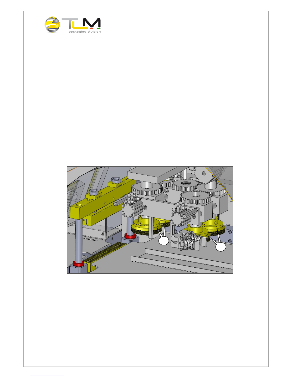
7.5 Welding group
The welding group is composed of four rollers that weld the film along the
longitudinal axis and two jaws that weld the film on the transversal axis and cut
the packaging. These four rollers are placed over the running surface of the
product.
WELDING ROLLERS
Before the two welding rollers (A) there are two cold dragging rollers (B) that drag
the product in the welding area. Inside the welding group there are the
resistances (both for the rollers and the jaws) equipped with probes that take the
welding temperature. The rollers for welding are equipped with a machined
welding surface that enables the hermetic welding during the transportation of the
film.
A
B
A
B
Use and Maintenance Handbook –Prime 400 Packaging Machine
Page 13 of 71
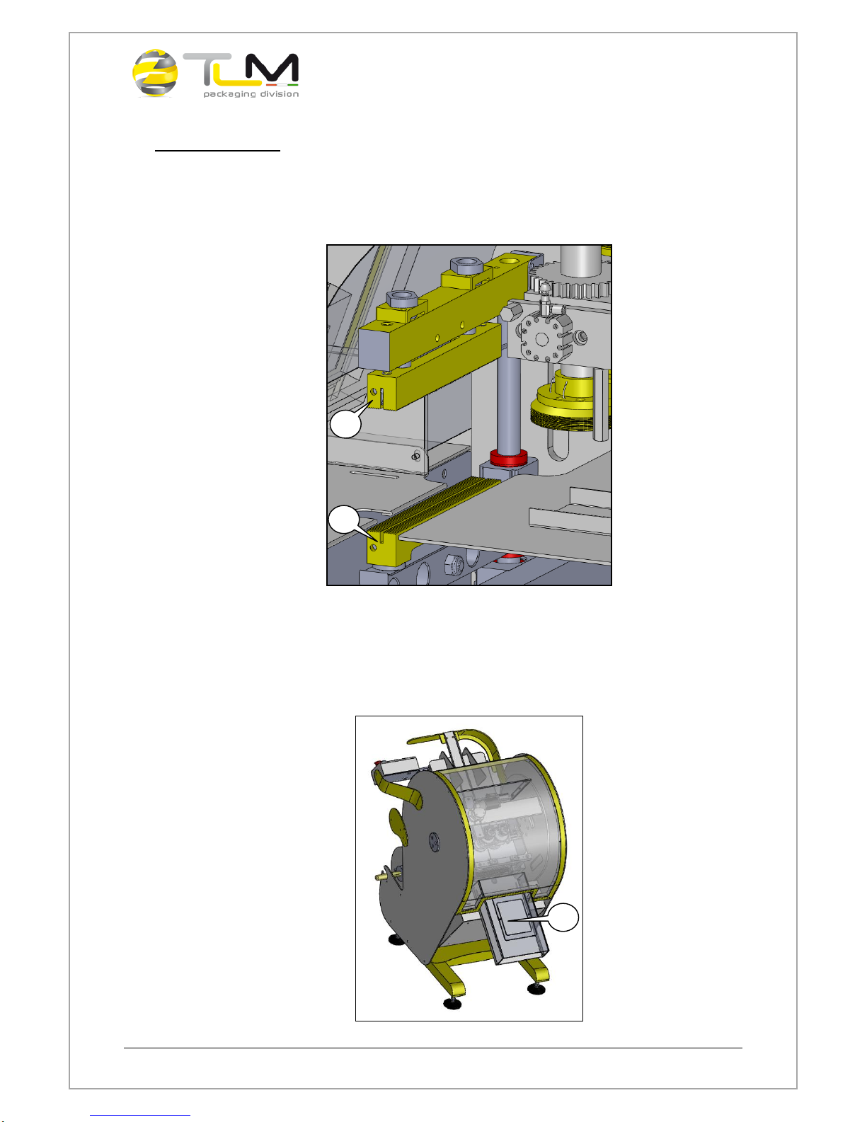
WELDING JAWS
Inside the two jaws –the upper one (C) and the lower one (D) –there is a slot.
The cutting blade is placed on the upper jaw. During the film cutting operation,
the blade can move inside the slot present on the lower jaw.
7.6 Discharge chute
The discharge chute (E) allows the exit of the packages coming from the
packaging machine. The packaged products are collected in an appropriate
container.
D
C
E

Use and Maintenance Handbook –Prime 400 Packaging Machine
Page 14 of 71
7.7 Pneumatic system
The customer is responsible for connetting the compressed air supply next to the
system. At the assembly, all the pneumatic control needed are done and any
further adjustment are not required.
For the pneumatic supply a max. 6 Bar pressure is required (3 Bar is adequate).
In order to change the pressure, an action on the top of the knob of the installed
regulator is needed. Rotating clockwise, the increase of the pressure in the
system increase, while rotating in counter-clokckwise sense, a decrease of the
pressure is reached.
CAUTION
THE CONVEYORS, THE DRAINING FILTERS AND OTHERS ACCESSORIES MUST
NEVER BE REMOVED WHILE THE SYSTEM IS UNDER PRESSURE.
CAUTION
BEFORE CARRYING OUT ANY KIND OF INTERVENTION, TURN OFF THE
COMPRESSED AIR SUPPLY LINES AND RELEASE THE PRESSURE FROM THE
SYSTEM.
For specific information on the pneumatic system refer to the technical
documentation provided with this manual.
Use and Maintenance Handbook –Prime 400 Packaging Machine
Page 15 of 71
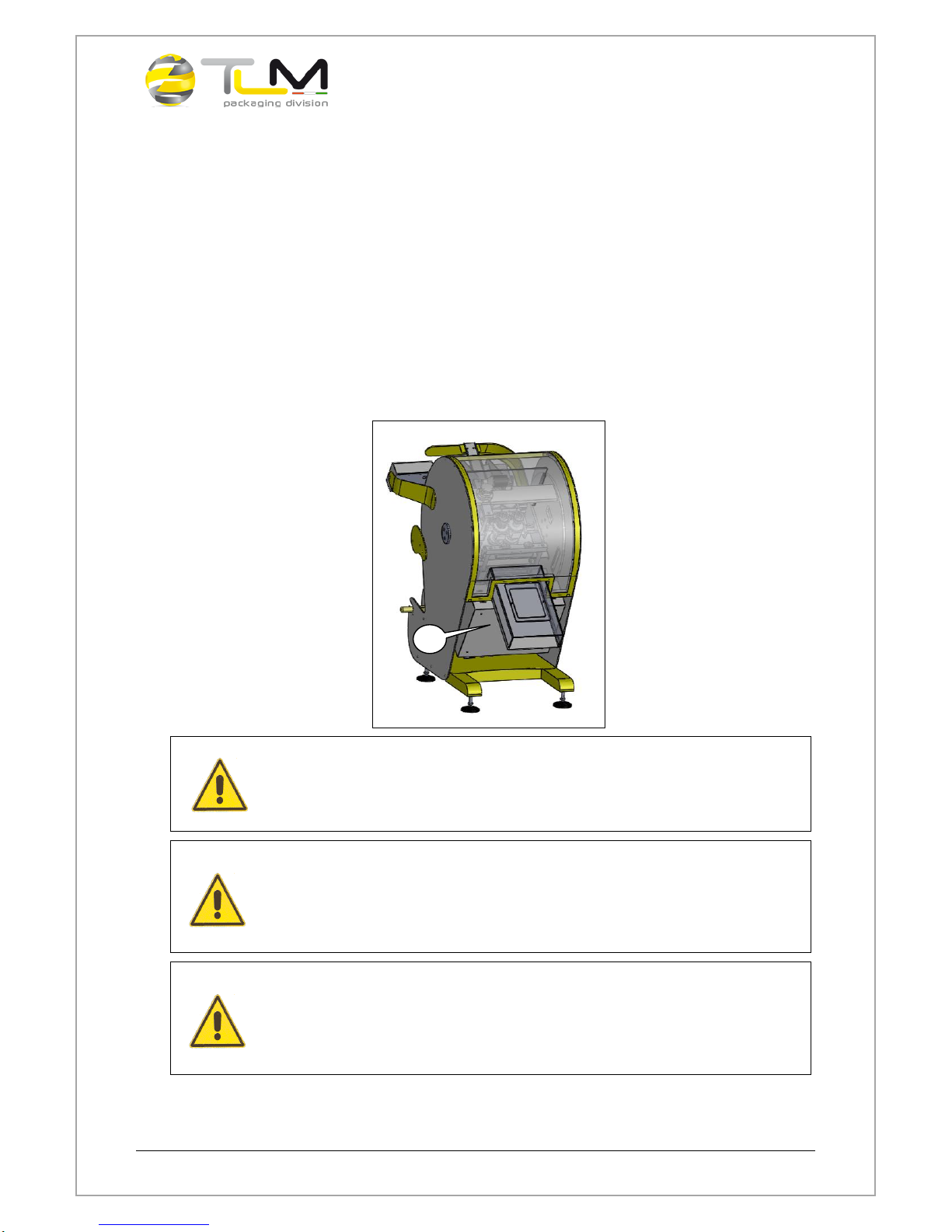
7.8 Electrical System
The packaging machine is supplied with a complete electrical system with wiring
on the machine. The electrical cabinet (A) is located in the rear of the machine,
below the discharge chute. The customer is responsible for connecting the
factory’s electrical cabinet and the main electrical panel, as well as connecting
the main electric panel to others apparatus where there are enabling interchange
signals to synchronised operations. The characteristics of the connections are
shown on the plate on the electrical panel and in the technical documentation
attached to this manual.
CAUTION
BEFORE CARRYING OUT ANY INTERVENTION ON THE ELECTRIC SYSTEM MAKE
SURE THAT IT IS NOT LIVE AND THAT ANY ACCUMULATIONS DEVICES ARE
DISCHARGED OR DISCONNECTED FROM THE SYSTEM.
CAUTION
BEFORE CARRYING OUT THE ELECTRICAL CONNECTION MAKE SURE THAT THE
ELECTRICAL CHARACTERISTICS CORRESPOND WITH THOSE SHOWN ON THE
IDENTIFICATION RATING PLATE OF THE SYSTEM AND THAT THE MACHINE HAS
BEEN FITTED WITH EARTHING.
CAUTION
WHEN CARRYING OUT THE CONNECTIONS CAREFULLY CHECK THE NUMBERING
OF THE CABLES AND THE JAWS REFERRING TO THE WIRING DIAGRAM, THE
POLARITY OF THE POWER SUPPLIES AND THE DIRECTION THE MOTORS
ROTATE.
For specific information on the Electric/Software system refer to the
technical documentation provided with this manual.
A

Use and Maintenance Handbook –Prime 400 Packaging Machine
Page 16 of 71
7.9 Technical specifications
LENGHT
860 mm
WIDTH
1300 mm
HEIGHT
1400 mm
POWER SUPPLY
220 Volt –50/60 Hz
INSTALLED POWER
3 kW
OPERATING AIR PRESSURE
3 Bar
MAXIMUM AIR PRESSURE
6 Bar
PIECES PRODUCTS
20 for minute
ENVIRONMENTAL CONDITIONS FOR USE
LOCAL
CLOSED
MIN TEMPERATURE
- 10 °C
MAX TEMPERATURE
40 °C for a period of 24h average
max. temperature 35 °C
RELATIVE HUMIDITY
max 50% - R.U. at 40 °C
MAX ALTITUDE
2000 m
ENVIRONMENTAL CONDITIONS FOR STORAGE
LOCAL
CLOSED
MIN TEMPERATURE
-10 °C
MAX TEMPERATURE
40 °C
RELATIVE HUMIDITY
max 50% - R.U. at 40 °C
Use and Maintenance Handbook –Prime 400 Packaging Machine
Page 17 of 71
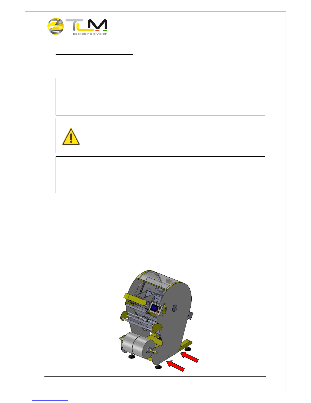
8. TRANSPORT AND HANDLING
For the handling and raising of the machine it is necessary to use the lower cross
beams of the frame with a forklift truck suitable for the weights indicated in the
relevant table of technical specifications.
While handling the entire surrounding area must be considered a danger area.
Make sure that nobody is in the danger area.
Do not stop or move under the suspended weights.
Keep the load at minimum distance from the ground.
!
CAUTION
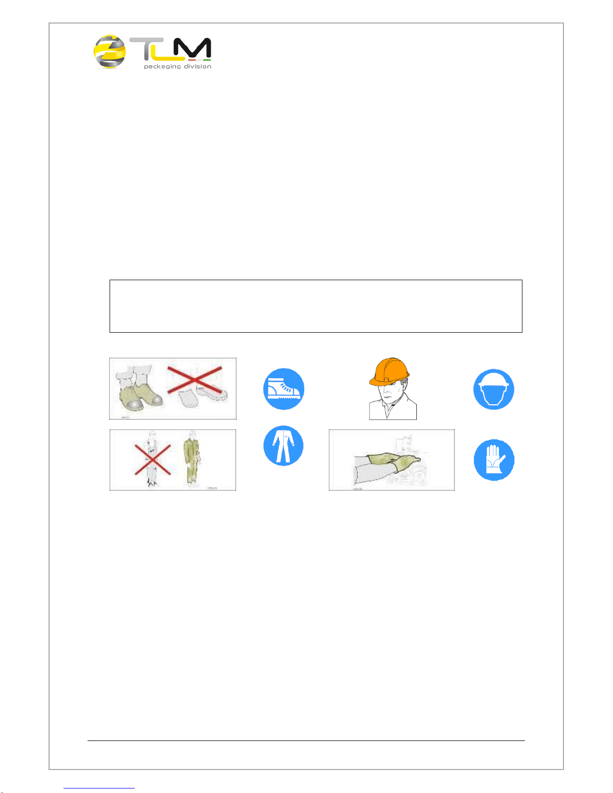
DURING THE MOVEMENT OPERATION, THE USE OF THE RECOMMENDED PPE IS
COMPULSORY
WITHOUT LOOSE
OR HANDLING
PARTS
Handling operations must only be carried out specialised personnel taking into
account the following regulations:
Operations to be carried out with the maximum care being careful to make
sure that the instruments are efficient.
Delineate with barriers the area where the operation is carrying-out
Avoid knocks and back kicks during all the phases: during the raising and
during the movement and setting down.
Use and Maintenance Handbook –Prime 400 Packaging Machine
Page 18 of 71
Handling with a forklift truck
In order to lift the machine with a forklift truck with driver on board o with the
driver on the ground, check the capacity for the mass to be lifted.
!
CAUTION
THE CAPACITY OF THE LIFTING EQUIPMENT MUST BE SUFFICIENT FOR THE
MASS TO BE HANDLED. ADHERE CLOSELY TO THE SAFETY REGULATIONS
DANGER
WHEN LIFTING AND MOVING THE MACHINES DO NOT STAND NEARBY. KEEP AT
A DISTANCE OF MORE THAN 2 METERS FROM THE LOAD.
!
CAUTION
THE MANUFACTURER DECLINES ALL LIABILITY FOR ANY INJURY TO PERSONS
OR DAMAGE TO PROPERTY CAUSED BY IMPROPER HANDLING OF THE LOADS
CARRIED OUT BY UNSUITABLE PERSONS AND:OR WITH LIFTING EQUIPMENT
THAT IS NOT ADEQUATE.
The operations to be carried out for moving are:
Cut off the power supply;
Properly lock all the mobile parts in order to avoid damaging or that they
suddenly get open during the transport phases;
Protect the equipment in order to prevent it from getting damaged during the
transport;
Use the appropriate lifting pockets suitable for the handling.

Use and Maintenance Handbook –Prime 400 Packaging Machine
Page 19 of 71
9. INSTALLATION
The machine that this manual refers to is installed in a workshop environment.
For the purpose of making installation possible, the floor on which the equipment
is to be placed must be checked to make sure it is flat and solid. To get the best
results in the production cycle, the floor must not be subject to vibrations. It is
advisable to make preliminary study in such a way as to optimise the accessibility
to the machine so as to be able to:
Carry out the installation,
Obtaining the spaces for manoeuvre,
Carrying out Use and Maintenance interventions
To check the exact levelling of the machine proceed as indicated below:
Place the bubble level on the machine plan.
Check the levelling eventually insert specifics thickness
Complete the operation by pulling the fastening nuts in order that the machine
stand uniformly on the floor.

Use and Maintenance Handbook –Prime 400 Packaging Machine
Page 20 of 71
10. SAFETY
The machine responds to the essential safety requisites conforming with what
has been described in Appendix 1 of the Machine Directive 2006/42/EC. In this
chapter all the possible risks that the machine in question might present including
in environmental and air and water pollution terms are considered.
CAUTION
THE MACHINE IS SUPPLIED WITH PERIMETRIC PROTECTIONS AND SAFETY
DEVICES, IN ORDER TO PACKAGE PRODUCTS FROM VARIOUS SECTORS,
INCLUDING FOOD SECTOR, INTO SPECIFICS BAGS.
THE MACHINE, AS PLANNED BY ITS INTENDED USE, IS REALIZED TO RUN WITH
THE PROTECTIONS AND THE SAFETY DEVICES ACTIVED AND INSTALLED.
TO THE USER: IT’S ABSOLUTELY PROHIBITED ALTERING OR TAMPERING THE
MACHINE, EVEN PARTIALLY, IF NOT AGREED UPON BY THE CONSTRUCTOR; IN
CASE OF NON-COMPLIANCE WITH THIS RULE, THE CONSTRUCTOR CANNOT BE
HELD RESPONSIBLE
CAUTION
DO NOT USE OR CARRY OUT INTERVENTIONS ON THE UNIT BEFORE READING THIS
INSTRUCTION MANUAL.
!
CAUTION
ADHERE TO THE SAFETY INSTRUCTIONS IN THIS MANUAL.
!
CAUTION
IT’S PROHIBITED TO USE THE MACHINE FOR ANY OTHER THINGS THAN THE ONE
INDICATED IN THIS MANUAL.
!
CAUTION
THE MANUFACTURER DOES NOT ASSUME ANY LIABILITY IN THE CASE OF
FAILURES, PROBLEMS OR INJURIES DUE TO THE NON-COMPLIANCE WITH WHAT IS
SET FORTH IN THIS MANUAL
!
CAUTION
THE DANGERS FOR THE PERSONNEL WORKING ON THE MACHINE CAN ONLY BE
ELIMINATED IF IT IS PROPERLY USED AS INDICATED IN THIS DOCUMENT, BY
SKILLED PERSONNEL WITH PROPER TECHNICAL TRAINING.
Table of contents
Popular Packaging Equipment manuals by other brands


AirSaver
AirSaver F2 Safety instructions, setup & installation manual

HUALIAN
HUALIAN M-PE Series Operation manual

Pro Pack Solutions
Pro Pack Solutions Eagle 710 Operation manual

Oliver
Oliver 1808-D User's operation

Kronos
Kronos H-46 Series Operation, safety and spare parts manual

Robopac
Robopac ROBOT S7 Use and maintenance manual