TLV Pocket TrapMan PT1 User manual

172-65411MA-05 (PT1) 5 June 2019
Pocket TrapMan®
PT1
Copyright © 2019 by TLV CO., LTD.
All rights reserved

172-65411MA-05 (PT1) 5 Jun 2019
1
Introduction
Thank you for purchasing the TLV Pocket TrapMan PT1.
When the product is delivered, before doing anything else, check the specifications
and external appearance to make sure nothing is out of the ordinary. Also be sure to
read this manual carefully before use and follow the instructions to be sure of using the
product properly.
To ensure safe and correct use of this product, be sure to observe the safety
precautions listed in this manual as they relate to installation, operation, maintenance
and repair of the product. Please keep it in a safe place for future reference.
TLV accepts no responsibility for incorrect use of the product by the customer or any
third-party, malfunction occurring during use, other defects and any damage caused
by this product, excluding cases in which it is under obligation to pay reparations by
law.
This product has undergone strict quality management and product inspection before
being shipped from the factory. However, in the event of malfunction or defects, please
contact your local TLV representative or the TLV customer service center.
This instruction manual and product are subject to modification without notice, for the
purpose of improvement.
Unauthorized reprinting or reproduction, in whole or in part, of this instruction manual
or product is strictly prohibited.
Contents
Introduction..................................................................................................... 1
1. PT1 Standard Set ....................................................................................... 2
2. Safety Considerations................................................................................. 3
3. Principles of Operation................................................................................ 6
4. Features and Functions.............................................................................. 7
5. Components, Features and Functions........................................................ 8
6. PT1 Preparation.......................................................................................... 9
7. Proper Measurement Procedure............................................................... 10
8. Steam Trap Diagnosis .............................................................................. 11
9. Valve Diagnosis........................................................................................ 16
10. Bearing Inspection .................................................................................. 18
11. Deleting Existing Data............................................................................. 22
12. Settings................................................................................................... 23
13. Accessories............................................................................................. 26
14. Troubleshooting...................................................................................... 27
15. Specifications.......................................................................................... 28
16. Product Warranty.................................................................................... 29

172-65411MA-05 (PT1) 5 Jun 2019
2
1. PT1 Standard Set
1. Instruction Manual (this manual)
2. Pocket TrapMan PT1
3. Soft Case
4. Earphones
5. Batteries (2 alkali AAA (LR03))
6. Cap
7. Carrying Strap
4. Earphones
5. Batteries
7. Carrying Strap
6. Cap
2. Pocket TrapMan PT1
3. Soft Case

172-65411MA-05 (PT1) 5 Jun 2019
3
2. Safety Considerations
Read this section carefully before use and be sure to follow the instructions.
Inspection, maintenance, repairs, disassembly, adjustment and valve
opening/closing should be carried out only by trained maintenance personnel.
The precautions listed in this manual are designed to ensure safety and prevent
equipment damage and personal injury. For situations that may occur as a result of
erroneous handling, three different types of cautionary items are used to indicate
the degree of urgency and the scale of potential damage and danger: DANGER,
WARNING and CAUTION.
The three types of cautionary items above are very important for safety: be sure to
observe all of them as they relate to use, maintenance and repair. Furthermore, TLV
accepts no responsibility for any accidents or damage occurring as a result of failure
to observe these precautions.
Symbols
Indicates a DANGER, WARNING or CAUTION item.
Indicates an urgent situation which poses a threat of death or
serious injury
Indicates that there is a potential threat of death or serious injury
Indicates that there is a possibility of injury or equipment / product
damage
This precautionary
symbol indicates an
item or action that must
not be used or
performed
MANDATORY
This precautionary
symbol indicates an
action or precaution that
MUST be performed or
observed
2.1 PT1 Precautions
DANGER
Do not use the carrying strap or earphones if there is any
possibility of entanglement with rotating machinery.
Operating the unit with the strap or earphone cord hanging loosely
could lead to accidents resulting in serious injury caused by their
becoming caught in rotating machinery.
Do not use in areas requiring explosion-proof equipment.
The unit does not have an intrinsically safe rating. Use in such
dangerous environments may result in ignition or accidental explosions.
Continued on next page
DANGER
WARNING
CAUTION
172-65411MA-05 (PT1) 5 Jun 2019
4
WARNING
Do not disassemble or modify.
Failure to observe this precaution could result in injury, electrical
shock, ignition or fire.
Do not operate the buttons or stare at the screen while walking.
Failure to observe these precautions could lead to accidents such as
tripping or collisions.
MANDATORY
Be attentive to the background noises in the surrounding area.
When wearing the earphones, it becomes difficult to hear noises from
the surrounding area. Operate the unit together with a person who is
not wearing any earphones or take measures during operation to
ensure advance awareness of potential dangers in the surrounding
area.
Do not turn the power ON while wearing the earphones.
A sudden loud sound may be emitted, leading to hearing impairment or
injury. After turning the power ON, check to see whether a loud sound
is being output before putting on the earphones.
Do not subject the unit to strong impact and do not throw it.
Such handling could result in leakage of the battery fluid, excessive
heat generation or injury.
Do not place components in microwave ovens or high- pressure
vessels, and do not place components in the vicinity of
electromagnetic devices.
Such handling could result in excessive heat generation, smoke,
damage to circuitry, battery leakage, rupture or ignition.
CAUTION
Make sure no foreign matter gets inside the unit.
Before use in areas with large amounts of metal powder or other fine
foreign matter, take measure to prevent this foreign matter from getting
inside the unit. The presence of such foreign matter could result in fire
or unit failure.
Do not let the unit become wet.
If liquid gets inside the unit, it may result in excessive heat generation,
electrical shock or unit failure. Be mindful of the location of use and the
method of handling.
172-65411MA-05 (PT1) 5 Jun 2019
5
2.2 Battery Precautions
DANGER
Do not apply heat to the
batteries or throw them
into a fire.
Failure to observe this
precaution could result in
leakage of the battery fluid,
excessive heat generation,
rupture or ignition.
Do not cause the unit to
become wet by immersing
in water, salt water or
liquid chemicals. Failure
to observe this precaution
could result in leakage of the
battery fluid, excessive heat
generation, rupture or ignition.
MANDATORY
If fluid leaks from the
battery and gets in the
eyes, flush it out.
Do not rub the eyes, and
after immediately flushing
out thoroughly with clean
water, see a doctor.
Do not disassemble,
modify, solder, etc.
Failure to observe this
precaution could result in
leakage of the battery fluid,
excessive heat generation,
rupture or ignition.
Do not leave unit where it will be exposed to direct sunlight or in
areas that will become very hot, such as interiors of cars, near
heating equipment, etc.
Failure to observe this precaution could result in leakage of the battery
fluid, excessive heat generation, rupture or ignition.
WARNING
MANDATORY
Cease use of the batteries immediately if the unit exhibits
abnormal operation.
If irregularities such as fluid leakage, an unusual smell, unusual heat
generation, discoloration or deformation are noticed, cease use of the
unit immediately. If use is continued under such conditions, excessive
heat generation, ignition or rupture may result.
MANDATORY
If battery fluid leaks and comes into contact with the body, rinse
immediately.
There is danger of resultant damage to the skin. Immediately rinse any
battery fluid off with clean water.
CAUTION
MANDATORY
When not intending to use for extended periods of time, remove
the battery pack from the unit and store in a dry, cool, dark
location.
Failure to observe this precaution could result in fluid leakage, rust,
deterioration in performance or a reduction in service life.
Do not dispose batteries with normal garbage.
If at any time the batteries become unusable, observe your company
regulations for proper disposal in accordance with local laws. If proper
disposal is impossible, insulate the contact terminals by covering them
with tape and return them to a TLV office.
172-65411MA-05 (PT1) 5 Jun 2019
6
3. Principles of Operation
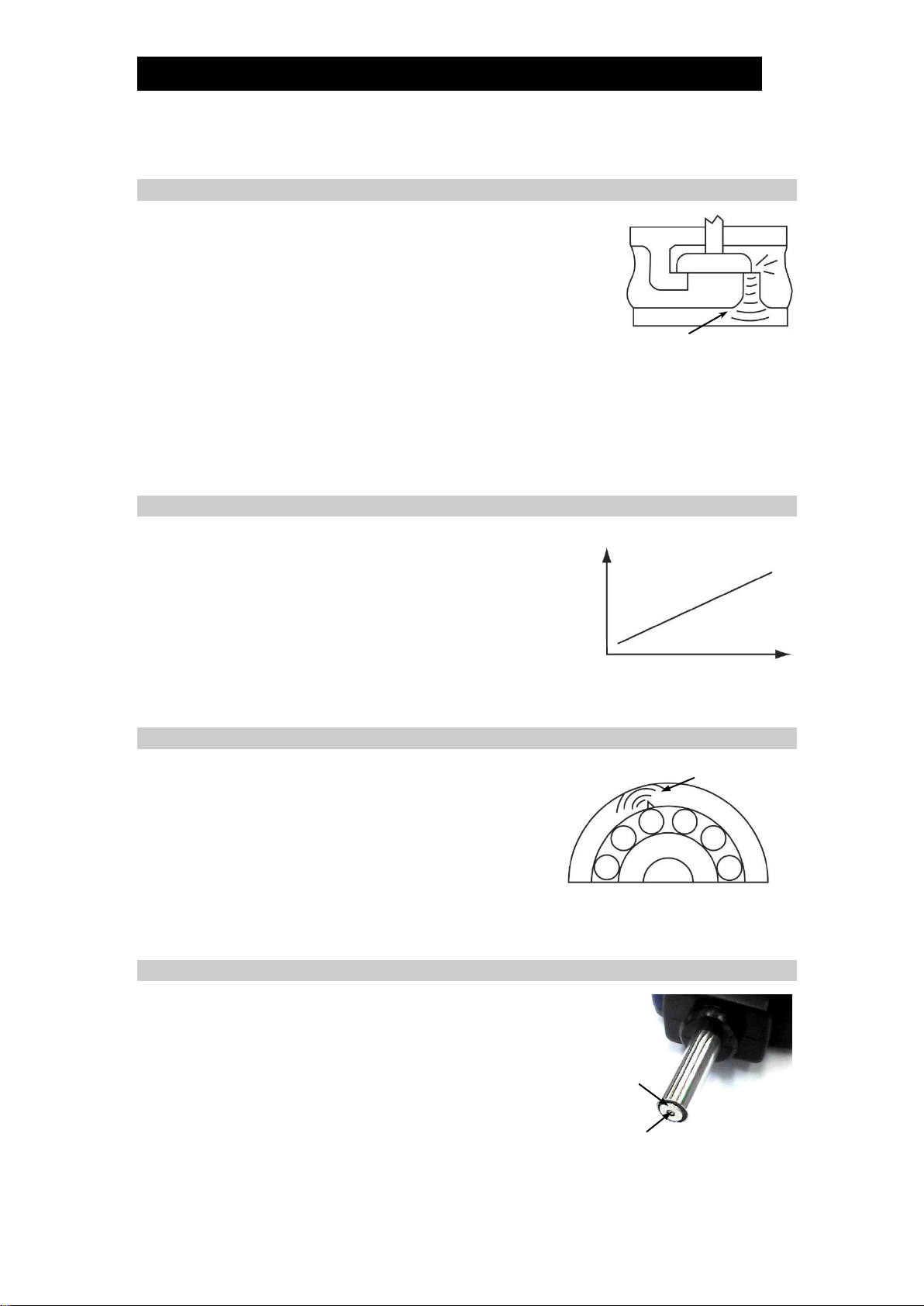
3.1 Generation of Ultrasonic Sound (Trap & Valve)
When fluid rapidly passes through a small hole, it
generates ultrasonic sound.
When fluid leaks through the seat in a steam trap or valve,
it emits ultrasonic sound. (Ultrasonic refers to the very
high-frequency range of sound that is above the threshold
of human hearing.)
Since this ultrasonic sound is generated by an amount of leakage that would otherwise
be too small to be noticed by human perception, checking for ultrasonic sound enables
the detection of deteriorated steam traps or valves at a very early stage.
As liquids generate much lower intensity ultrasonic sound levels than gases, PT1 should
only be used on steam traps, or valves installed on steam, air and other gas systems.
3.2 Ultrasonic Intensity & Steam Leakage Correlation (Trap & Valve)
There is a correlation between the intensity of the
ultrasonic sound generated by a leak and the amount
of steam leakage.
Pocket TrapMan PT1 judges the trap or valve
operational condition by measuring the intensity of the
ultrasonic sound and comparing it with a standard set
of precisely measured values obtained from
experimentation.
3.3 Ultrasonic Shock Pulse Generation (Bearing)
Shock pulses are generated whenever two metals
collide. For bearings, they are generated from
contact between the races due to insufficient
lubrication or damage from wear.
As there is a correlation between the intensity of the
shock pulse generated, the degree of damage and
the velocity of the contact (rotation frequency / shaft size), the operational condition of
a bearing can be determined by measuring the intensity of the shock pulse.
3.4 Surface Temperature Measurement (Trap & Valve, Bearing)
Pocket TrapMan PT1 can measure surface
temperature and ultrasonic sound simultaneously.
Temperature data can be used to detect blockage in
steam traps and can be utilized to help determine the
condition of bearings.
Ultrasonic Sound Wave
Ultrasonic Sound
Intensity
Amount of Leakage
Shock Pulse
Temperature
Sensor
Ultrasonic
Wave Sensor

172-65411MA-05 (PT1) 5 Jun 2019
7
4. Features and Functions
4.1 Steam Trap Operation Inspection
1) PT1 automatically inspects the steam trap and makes a judgement estimate regarding
the basic operational condition (Good / Caution / Leaking /Blocked / Low Temp).
Note: [Good] judgments for Temperature Control (Adjustable) Steam Traps must
be confirmed manually. Compare the internal temperature and the allowed
temperature range to confirm proper operating conditions. There is no
[LowTemp] judgement for Temperature Control (Adjustable) Steam Traps.
2) Ideal for systems where detailed steam trap management is not implemented, or
for daily inspections of critical systems between annual steam trap surveys. Using
PT1 for a daily inspection is an effective way to determine whether maintenance is
required or not.
4.2 Valve Seal Inspection
1) PT1 automatically inspects the valve and makes a judgement estimate regarding
the condition of the valve’s seal (Good/Caution/Leaking).
2) PT1 is effective for determining whether or not a valve is properly closed.
4.3 Bearing Deterioration Inspection
1) PT1 is effective for collecting the data regarding a bearing’s operational
characteristic.
2) Bearing deterioration (lack of lubricant, ball wear, etc.) can be determined based
on the collected data.
Note: PT1 cannot detect structural or configuration problems (such as misalignment,
being unbalanced, etc.) in rotating equipment.
4.4 Simultaneous Surface Temperature Measurement
1) As surface temperature is measured simultaneously with ultrasonic sound
(vibration), a separate temperature measurement is unnecessary.
2) PT1 can be used for any application requiring surface temperature measurement.
4.5 Measurements Start and Stop Automatically
1) Measurements begin automatically when the probe is set on the measurement point.
2) Measurements stop after a certain amount of time has elapsed (“Trap&Valve”
mode and “Bearing”mode), or after the probe is removed from the measurement
point (“Bearing”mode only).
4.6 Data Stored in Memory
1) Inspection data is automatically stored in memory after each measurement.
2) PT1 has two inspection modes, “Trap&Valve” mode and “Bearing” mode. Each
mode has 100 available memory locations (records).
Note: Steam trap inspection data and valve inspection data share the same memory
locations. Be careful not to overwrite one when measuring the other.
172-65411MA-05 (PT1) 5 Jun 2019
8
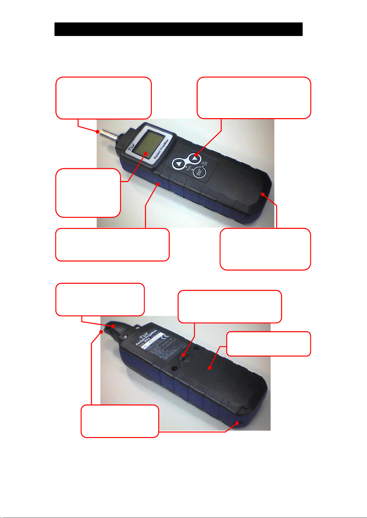
5. Components, Features and Functions
Probe:
On contact with object,
measures ultrasonic sound
and surface temperature.
Battery Compartment:
Holds 2 AAA batteries.
Key Pad:
Allows user to select modes,
records and data, save or delete,
and turn the unit ON/OFF.
Earphone Jack:
Open the rubber cover and insert
the included earphones here.
LED Indicator:
Displays status of the
present measurement by
being lit or by flashing.
Display:
Shows the mode
of operation and
measurement
results.
Battery Compartment Lock:
Prevents accidental opening
of the battery compartment.
Cap:
Protects the probe when
in storage or not in use.
Strap Anchor:
Possible locations for
attaching the strap.

172-65411MA-05 (PT1) 5 Jun 2019
9
6. PT1 Preparation
6.1 Inserting Batteries
1) Turn the battery compartment lock counter-clockwise to unlock.
2) Open the battery compartment and remove the battery pack (battery compartment
cover).
3) Insert 2 AAA (LR03) batteries into the battery pack. Make sure the batteries have the
correct orientation (polarity). (Rechargeable batteries, Ni-MH or Ni-Cd can be used.)
4) Reattach the battery pack and close the battery compartment.
5) Turn the battery compartment lock clockwise to lock.
Locked Position
Unlocked Position
Battery Pack
When not intending to use for extended periods of time, remove the battery
pack from the unit and store in a dry, cool, dark location.
6.2 Turning the Power ON/OFF
1) Press [ENT] to turn PT1 on. The initial screen will appear on the display after 2
seconds.
2) Press and hold the [ENT] key for more than 2 seconds to turn PT1 off.
3) The power will shut off automatically if 1 minute passes without a measurement
being taken and no keys being pressed.
Note: PT1 will not shut off if in the process of taking a measurement or when settings
are being changed.
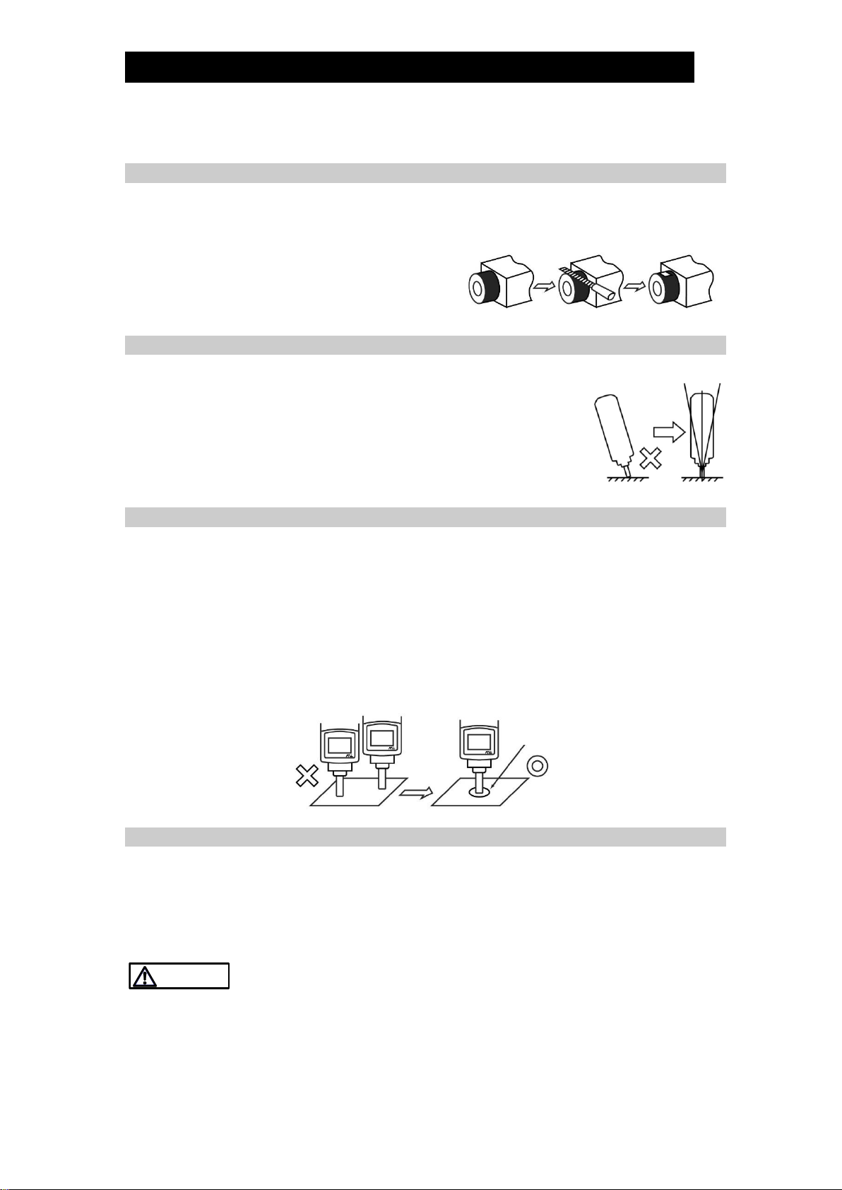
6.3 Removing and Attaching the Cap
1) To remove the cap, twist it 45° counter-clockwise and take it off.
2) To attach the cap, place it over the probe and twist 45°clockwise to secure.
CAUTION
Turn Counter-
clockwise to
Unlock
Turn
Clockwise
to Lock
172-65411MA-05 (PT1) 5 Jun 2019
10
7. Proper Measurement Procedure
7.1 Prepare Surface for Measurement
Ultrasonic sound and surface temperature cannot be measured accurately if the
surface where the measurement is to be taken is curved or a rough finished surface, or
if it is coated with paint, dirt, rust or scale.
File the measurement point to produce a
smooth and flat region of at least
ø8 mm (ø3/8in).
7.2 Probe Application
Hold the PT1 so that the probe is perpendicular to the
measurement surface.
If the probe is tilted or applied to the surface at an angle,
inconsistent contact with the surface will make it difficult to obtain
an accurate measurement. Try to keep the probe as
perpendicular and steady as possible during the measurement.
7.3 Consistent Measurement Point
Always take measurements from the same spot. If measurement points are different,
the measured data may also differ. Especially, when trying to observe trends in
measured values taken over time, it is likely to be more difficult to accurately identify
such trends, leading to misjudgment, if the point differs with every measurement.
Determine an appropriate measurement point first, and measure from the same point for
subsequent measurements. For convenience, mark the measurement point, but avoid
scoring the surface or making a small indentation on the surface as this may cause
inaccurate measurement.
7.4 Surface Temperature Restriction
The maximum allowable surface temperature of the object to be measured is 350 °C
(662 °F). If the surface temperature exceeds 350 °C (662 °F), “Over”appears on the
display and LED indicator will flash rapidly at four times per second. If you observe the
indicator flashing in such a rapid manner, quickly remove the PT1 probe from the
object, canceling the measurement.
Continuing measurement under conditions that exceed maximum allowable
surface temperature (350 °C, 662 °F) could result in temperature sensor
damage.
CAUTION
Mark
172-65411MA-05 (PT1) 5 Jun 2019
11
8. Steam Trap Diagnosis
The PT1 is equipped with a simple automatic diagnosis function for steam traps. This
section explains how to properly operate PT1 for steam trap inspections.
8.1 Mode Selection
1) Set the mode to “Trap&Valve”. If already set to
“Trap&Valve”, the following operation is unnecessary.
a) With the power on, simultaneously press [] [ENT].
b) Press [] or [] to highlight “Trap&Valve”.
c) Press and hold [ENT] for more than 1 second.
2) Set the mode to “Trap”. If already set to “Trap”, the
following operation is unnecessary.
a) If “Valve” is highlighted, simultaneously press [] [].
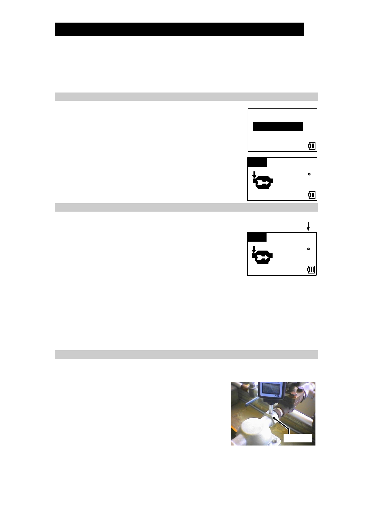
8.2 Set Record Number
1) Set the record number to use by pressing [] or [].
a) Pressing [] / [] once increments/decrements the
record number by 1.
b) Holding [] / [] for more than 1 second increments/
decrements record numbers more quickly.
Note: The record number cannot be changed after the
measurement is taken.
2) If any data is recorded at the selected record number, its contents are shown.
Note: If data is already recorded at the selected record number, taking a
measurement will overwrite the data.
3) Record numbers from 001 to 100 are available, records do not need to be saved
sequentially, and not all record numbers need to be used (numbers in the middle
can be skipped).
8.3 Take Measurement
Before proceeding with taking a measurement, be sure to read section “7. Proper
Measurement Procedure”.
1) Measurements should be taken from the inlet side of
the trap. If the measurement point is at the outlet,
measurement accuracy cannot be assured.
2) Press the probe against the measurement point.
Measurements begin automatically once the probe
is applied to the measurement point.
3) It takes 15 seconds after placing the probe against
the measurement surface for the measurement to be complete. Be sure to hold the
probe perpendicular and steady for this entire period.
Trap Inlet
Mode
Trap&Valve
Bearing
001
Trap /Valve
Check Inlet
C
---
-.--M
Pa
Record Number
001
Trap /Valve
Check Inlet
C
---
-.--M
Pa
172-65411MA-05 (PT1) 5 Jun 2019
12
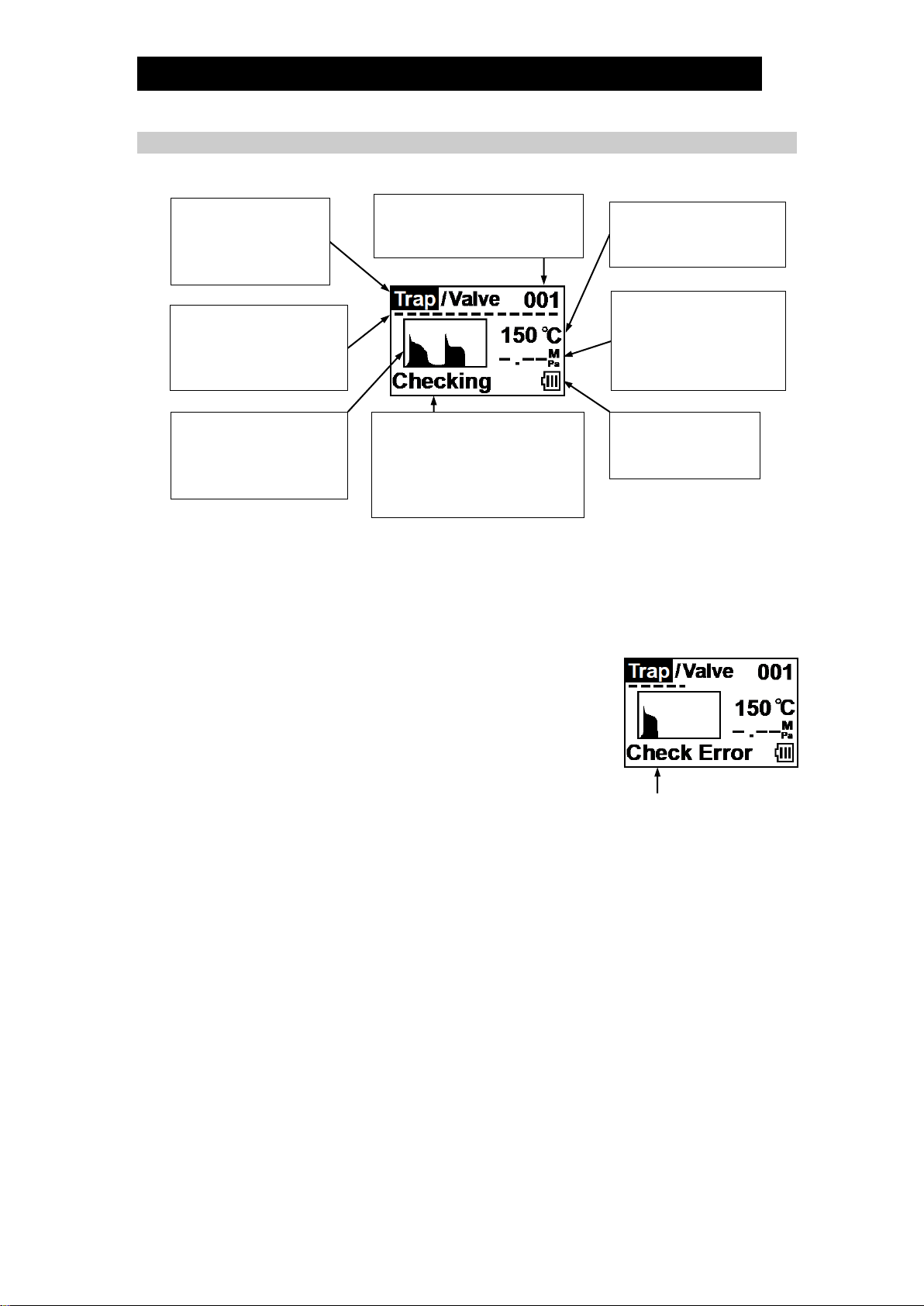
8.4 Display During Measurement
1) The following information is displayed while PT1 takes a measurement:
*When the measured surface temperature is higher than the measurable range,
“OVER”will be displayed. If it is lower than the measurable range, “UNDER”will
be displayed.
2) The LED at the base of the PT1 signals when a measurement is complete. It also
flashes rapidly if the surface temperature exceeds 350 °C (662 °F).
3) If the probe is moved during the measurement, or is held
at too high of an angle to the measurement surface, the
measurement will stop and an error comment will be
given.
Mode:
“Trap”is highlighted
indicating steam trap
diagnosis.
Record No.:
The record number at which
data will be saved.
Surface Temperature*:
The surface temperature
being measured.
Measuring Time
Indicator:
Shows the time elapsed
during measurement.
Measure Ultrasound:
Graphical depiction of
the ultrasound intensity
being measured.
Pressure:
The pressure set for
previous data (if any);
to be set or verified
after measurement.
Comments:
Displays any comments
regarding the measurement;
shows “Checking”during
normal measurements.
Battery Indicator:
The current battery
energy level.
Measurement Error

172-65411MA-05 (PT1) 5 Jun 2019
13
8.5a Set Pressure
Set the operating pressure of the trap.
Note: All displayed pressures are gauge pressures, not absolute pressures.
Note: Due to space limitations, pressure unit kg/cm2G is shown on the display as “KG”.
If no data was previously saved under this record number, “-,--” will be displayed.
If data was previously saved, the previous pressure will be highlighted.
1) Enter the pressure at which the steam trap is operating.
a) Press [] or [] to enter the desired pressure.
Increase or decrease pressure setting to the following
scale:
Displayed Unit
MPa
KG, bar
psi
Pressure Setting Range
0.00 - 0.09 MPaG
00.0 - 00.9 kg/cm2G, barg
000 - 009 psig
[] or []
by 0.01
by 00.1
by 001
Pressure Setting Range
0.10 - 0.95 MPaG
01.0 - 09.5 kg/cm2G, barg
010 - 095 psig
[] or []
by 0.05
by 00.5
by 005
Pressure Setting Range
1.00 - 9.90 MPaG
10.0 - 99.0 kg/cm2G, barg
100 - 990 psig
[] or []
by 0.10
by 01.0
by 010
b) Holding [] / [] for more than 1 second increases/decreases numbers more
quickly.
2) Press [ENT] to save the selected pressure.
8.5b Set Condensate load factor
Set the condensate load factor (MIN, ?, MAX).
If no data was previously saved under this record number,
“?”will be displayed as default.
If data was previously saved, the previous factor will be
displayed.
1) Select the condensate load factor under which the steam trap is operating.
a) The standards for selection of the condensate load factor are as follows:
Think of the condensate load factor as:
(Amt. of condensate currently being discharged)
(Trap capacity under operating conditions)
Use the following standards to select the factor.
Condensate load status
Less than 10%
More than 90%
10-90% or unknown
Factor
MIN
MAX
?
b) Press [] or [] to select the condensate load factor.
2) Press [ENT] to save the selected factor.
100 (%)
001
C
150
Trap /Valve
Select
Cond.
Load
:?
001
150
1.00
Trap /Valve
Inlet
Press.
Up&Down
C
M
Pa
172-65411MA-05 (PT1) 5 Jun 2019
14
8.5c Set Type of Steam Trap
Set the type of steam trap to be measured.
If no data was previously saved under this record number, [0:Disc] will be highlighted.
If data was previously saved, the previous trap type will be highlighted.
1) Select appropriate trap type from the following:
[0:Disc]: Disc (Thermodynamic)
[1:Float]: Float
[2:Bucket]: Bucket
[3:Thermo]: Thermostatic
[4:Temp.ADJ]: Temperature Control (Adjustable)
[5:Others]: Orifice type / Trap type Unknown
a) Press [] or [] to select the type of trap.
b) Press [ENT] to save the selected trap type.
8.6 Automatic Judgement
Based on the measured data, PT1 will automatically judge
the operational status of the steam trap. For steam trap
diagnosis, there are 5 possible judgements:
Good: The surface temperature is as expected, and there is
no detected ultrasonic sound. The steam trap is likely to be
in proper operational condition.
Caution: The surface temperature is as expected, but there is some ultrasonic sound
detected. The sound level is very low, so it is difficult to determine if the trap is operating
properly or if there is a very small leak. Continue to observe the steam trap closely.
Leaking: A large amount of high-intensity ultrasonic sound is detected. There is a high
possibility that the trap is leaking steam, and immediate repair or replacement is
recommended.
Blocked: The surface temperature is less than 40 °C (104 °F). The trap is most likely
blocked making condensate discharge impossible. Immediate cleaning, repair or
replacement is recommended.
LowTemp (other than temperature control traps): Measured surface temperature is
less than the saturation temperature at the input pressure 0.6. There is a high
possibility that the surface temperature has dropped due to condensate accumulation,
inlet pressure drop, closed inlet valve, or blocked inlet piping.
Note: The PT1 does not take the set temperature of Temperature Control (Adjustable)
Steam Traps into account, and therefore [Good] judgments must be confirmed
manually by comparing the internal temperature to the allowed temperature
range of the trap. The internal temperature is slightly higher than the measured
surface temperature.
When the judgement is displayed, the result is automatically saved at the designated
record number simultaneously.
001
Trap /Valve
0:Disc
1:Float
2:Bucket
001
Trap /Valve
3:Thermo
4:Temp.ADJ
5:Others

172-65411MA-05 (PT1) 5 Jun 2019
15
8.7 Retake Measurement and Proceed to Next Measurement
1) If the measurement or judgement is in doubt and you wish to verify by measuring
again, simply apply the probe to the measurement point again (see 8.3). The
measurement will restart automatically.
Note: The second measurement will overwrite the data from the first measurement;
the original data will be lost.
2) If the measurement and judgement are acceptable, proceed to next device.
a) Press [ENT] to save data. (“Check Inlet” will be displayed.)
3) If the next device to inspect is a steam trap, repeat operation from “8.2 Set Record
Number”.
4) If the next device to inspect is a valve, switch PT1 diagnostic modes.
a) Press [] [] simultaneously, changing mode to “Valve”.
b) Follow the instructions under section “9. Valve Diagnosis”.
5) If finished performing inspections, turn PT1 off.
a) Press and hold [ENT] for more than 2 seconds.

172-65411MA-05 (PT1) 5 Jun 2019
16
9. Valve Diagnosis
The PT1 is equipped with a simple automatic diagnosis function for valves. This
section explains how to properly operate PT1 for valve inspections.
PT1 is suitable for valve diagnosis on steam, air and other gas systems.
9.1 Mode Selection
1) Set the mode to “Trap&Valve”. If already set to
“Trap&Valve”, the following operation is unnecessary.
a) With the power on, simultaneously press [] [ENT].
b) Press [] or [] to highlight “Trap&Valve”.
c) Press and hold [ENT] for more than 1 second.
2) Set the mode to “Valve”. If already set to “Valve”, the
following operation is unnecessary.
a) If “Trap” is highlighted, simultaneously press [] [].
9.2 Set Record Number
This procedure is the same as for steam trap diagnosis described earlier. Refer to
section 8.2 for details.
9.3 Take Measurement
Before proceeding with taking a measurement, be sure to read section “7. Proper
Measurement Procedure”.
PT1 checks for valve leaks on closed valves. Make sure that the valve is fully closed
before taking a measurement.
Note: Some valves on critical systems should not be closed. Verify whether or not it is
acceptable to temporarily close the valve before proceeding to do so.
For valves, measurements may be required at up to 3 different locations; at the outlet,
upstream and downstream.
1) The first measurement must be taken at the piping
immediately after the valve outlet.
2) Press the probe against the measurement point.
Measurements begin automatically once the probe is applied
to the measurement point.
3) For valves, it takes 10 seconds after placing the probe against the measurement
surface for the measurement to be complete. Be sure to hold the probe
perpendicular and steady for this entire period.
Note: The display during measurement is the same as for steam trap diagnosis
except the mode displayed will be “Valve”. See section 8.4 for display details.
Mode
Trap&Valve
Bearing
001
Check Outlet
C
---
Trap/Valve

172-65411MA-05 (PT1) 5 Jun 2019
17
4) There are two possible outcomes from the measurement at the valve’s outlet:
a) No ultrasonic sound was detected and the valve
seals properly. Proceed to section “9.4 Automatic
Judgement”.
b) Ultrasonic sound was detected and further
inspection is required. Continue to step 5.
5) If after taking a measurement at the outlet the screen
shown right appears, further measurements are required.
The second measurement is taken about 50 cm (2 ft)
upstream of the valve.
6) After the upstream measurement, a third measurement is
required about 50 cm (2 ft) downstream of the valve.
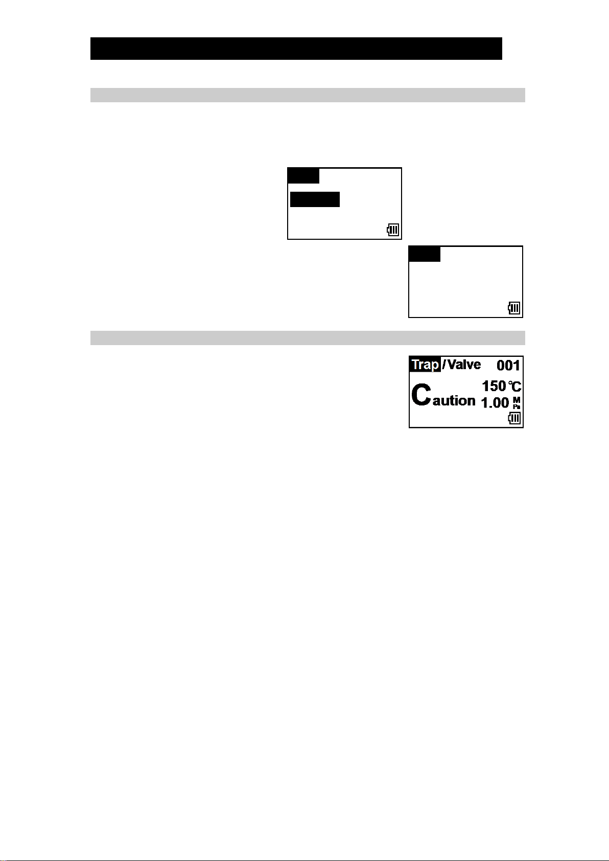
9.4 Automatic Judgement
Based on the measured data, PT1 will automatically judge
the operational status of the valve. For valve diagnosis,
there are 3 possible judgements:
Good: No ultrasonic sound originating from the valve was
detected. The valve seems to seal properly without leakage.
Caution: There is some ultrasonic sound detected. The sound level is very low, so it is
difficult to determine if the valve seals properly or if there is a very small leak. Continue
to observe the valve closely.
Leaking: A large amount of high-intensity ultrasonic sound is detected. The valve is
likely leaking fluid, and immediate repair or replacement is recommended.
When the judgement is displayed, the result is automatically saved at the designated
record number simultaneously.
9.5 Proceed to Next Measurement
1) If the measurement or judgement is in doubt and you wish to verify by measuring
again, simply apply the probe to the measurement point at the valve outlet again
(see 9.3). The measurement will restart automatically.
Note: The second measurement will overwrite the data from the first measurement;
the original data will be lost.
2) If the measurement and judgement are acceptable, proceed to the next device.
a) Press [ENT] to save data. (“Check Outlet” will be displayed.)
3) Reopen the valve if it was open before performing the inspection.
4) If the next device to inspect is a valve, repeat operation from step 9.2.
5) If the next device to inspect is a steam trap, switch PT1 diagnostic modes.
a) Press [] [] simultaneously, changing mode to “Trap”.
b) Follow the instructions under “8. Steam Trap Diagnosis”.
6) If finished performing inspections, turn PT1 off.
a) Press and hold [ENT] for more than 2 seconds.
C
150
Trap/ Valve 001
Caution

172-65411MA-05 (PT1) 5 Jun 2019
18
10. Bearing Inspection
The PT1 can measure and display vibration acceleration levels (dB). This information
is useful for checking and determining the operational condition of bearings. This
section explains the features and proper measurement procedure for using PT1 for
bearing inspections.
10.1 Special PT1 Features for Bearing Inspections
PT1 has several special functions particular to its bearing inspection mode.
1) Bearing measurement data can be displayed in three different modes. Refer to
“10.5 Display During and After Measurement” for details on displayed information,
and section “12.3 View Mode Selection” for instructions on how to modify this
display setting.
2) The average value from 9 individual measurements can be saved for one record.
This is used when measurements are subject to high fluctuations and a longer
term average is desired. See 10.6 for procedure details.
3) The CF (Crest Factor) value is automatically calculated and displayed. If the CF
value is large, the bearing may be scratched or damaged; if the CF value is small,
new lubrication packing may be required.
4) The LED indicator on the PT1 will flash once preset conditions for the
measurement completions have been reached. See section “12.7 LED Indicator
Flash Setting” for setting detail. The possible set conditions are as follows:
- 10 seconds have passed since the measurement began
- The measured vibration acceleration level stabilizes
- The surface temperature stabilizes
5) One of two different calculation methods can be selected. See section “12.6
Calculation Type” for selection details.
Converge: The average measured value from all intervals is displayed. The value
converges with time as instantaneous measurements vary.
Interval:The value from the current measurement interval is displayed. This is
useful to visualize instantaneous variations.
10.2 Mode Selection
1) Set the mode to “Bearing”. If already set to “Bearing”,
the following operation is unnecessary.
a) With the power on, simultaneously press [] [ENT].
b) Press [] or [] to highlight “Bearing”.
c) Press and hold [ENT] for more than 1 second.
Mode
Trap&Valve
Bearing

172-65411MA-05 (PT1) 5 Jun 2019
19
10.3 Set Record Number
1) Set the record number to use by pressing [] or [].
a) Pressing [] / [] once increments/decrements the
record number by 1.
b) Holding [] / [] for more than 1 second increments/
decrements record numbers more quickly.
Note: The record number cannot be changed after the
measurement is taken.
2) If any data is recorded at the selected record number, its contents are shown.
Note: If data is already recorded at the selected record number, taking a
measurement will overwrite the data.
3) Record numbers from 001 to 100 are available, records do not need to be saved
sequentially, and not all record numbers need to be used (numbers in the middle
can be skipped).
10.4 Take Measurement
Before proceeding with taking a measurement, be sure to read section “7. Proper
Measurement Procedure”.
1) As it is impossible to take a measurement directly from the bearing itself, select a
point on the housing as close to the bearing as possible.
Avoid taking measurements at dangerous locations or from places that
require dangerous body positioning.
2) Determine one measuring point, and always measure from the same angle and
orientation.
3) Press the probe against the measurement point. Measurements begin
automatically once the probe is applied to the measurement point.
4) A single measurement can be taken for as long as 1 minute. After 1 minute, the
measurement ends automatically. Measurements can be stopped sooner if desired
(i.e. the LED is flashing to indicate preset conditions have been reached).
In such a case, simply lift the probe off of the measurement point to end
measurement.
CAUTION
Record Number
001
30
CF: 5
P: 85dB
Bearing
C
dB80
Table of contents


