TLV JH8R-X User manual

Instruction Manual
Free Float Steam Trap with X-element: JH8R-X
172-65463M-05
Publication date 5 August 2022
Copyright © 2022 TLV CO., LTD.

Table of Contents
Introduction ............................................................................................................................... 3
Safety Considerations .............................................................................................................. 4
Checking the Piping .................................................................................................................. 6
Operation .................................................................................................................................. 7
Specifications ........................................................................................................................... 9
Configuration .......................................................................................................................... 10
Installation .............................................................................................................................. 12
Maintenance ........................................................................................................................... 13
Disassembly/Reassembly ...................................................................................................... 15
Instructions for Plug/Holder Disassembly and Reassembly ................................................... 18
Troubleshooting ...................................................................................................................... 19
TLV EXPRESS LIMITED WARRANTY ................................................................................... 20
Service ................................................................................................................................... 22
Options ................................................................................................................................... 23
2

Introduction
Thank you for purchasing the TLV free float steam trap.
This product has been thoroughly inspected before being shipped from the factory. When
the product is delivered, before doing anything else, check the specifications and external
appearance to make sure nothing is out of the ordinary. Also be sure to read this manual
carefully before use and follow the instructions to be sure of using the product properly.
This free float steam trap employs a hinge-less and lever-less free float to rapidly,
automatically and continuously discharge the inflowing condensate that is continuously
generated inside the equipment, thus preventing the accumulation of condensate and thereby
improving the heat transfer efficiency of the equipment. This steam trap is also of a
revolutionary design featuring an integral air vent that employs a high-performance X-element.
The X-element is very sensitive to changes in temperature, and responds with great accuracy.
As a result, air and the large quantities of condensate created immediately after the start-up
of operation are quickly discharged, thereby greatly reducing start-up time and also proving
useful in valve operation (bypass blowdown) labor-saving.
The X-element is also sensitive to hot air during operation, responding quickly and thus
preventing the occurrence of air binding. These features make this free float steam trap
ideally suited for use on process systems and equipment (steam-using equipment), and it
is especially well-suited for removing condensate from equipment used for batch operations,
which often experience entrained air during operation.
If detailed instructions for special order specifications or options not contained in this manual
are required, please contact TLV for full details.
This instruction manual is intended for use with the model(s) listed on the front cover. It is
necessary not only for installation, but for subsequent maintenance, disassembly/reassembly
and troubleshooting. Please keep it in a safe place for future reference.
3
Safety Considerations
• Read this section carefully before use and be sure to follow the instructions.
• Installation, inspection, maintenance, repairs, disassembly, adjustment and valve opening/
closing should be carried out only by trained maintenance personnel.
• The precautions listed in this manual are designed to ensure safety and prevent equipment
damage and personal injury. For situations that may occur as a result of erroneous handling,
three different types of cautionary items are used to indicate the degree of urgency and the
scale of potential damage and danger: DANGER, WARNING and CAUTION.
• The three types of cautionary items above are very important for safety: be sure to observe
all of them as they relate to installation, use, maintenance and repair. Furthermore, TLV
accepts no responsibility for any accidents or damage occurring as a result of failure to
observe these precautions.
Cautionary items and definitions
Danger
Indicates an urgent situation which poses a threat of death or serious injury
Warning
Indicates that there is a potential threat of death or serious injury
Caution
Indicates that there is a possibility of injury or equipment/product damage
Safety Considerations for the Product
Warning
NEVER apply direct heat to the float. The float may explode due to increased internal pressure,
causing accidents leading to serious injury or damage to property and equipment.
Caution
Install properly and DO NOT use this product outside the recommended operating
pressure, temperature and other specification ranges. Improper use may result in such
hazards as damage to the product or malfunctions that may lead to serious accidents. Local
regulations may restrict the use of this product to below the conditions quoted.
Caution
DO NOT use this product in excess of the maximum operating pressure differential. Such
use could make discharge impossible (blocked).
Caution
Use hoisting equipment for heavy objects (weighing approximately 20 kg (44 lb) or more).
Failure to do so may result in back strain or other injury if the object should fall.
Caution
Use the eye bolts for removing the cover only; DO NOT use the eye bolts for hoisting the
product. Eye bolts may break under strain, possibly resulting in serious injury.
Caution
Take measures to prevent people from coming into direct contact with product outlets.
Failure to do so may result in burns or other injury from the discharge of fluids.
4
Caution
When disassembling or removing the product, wait until the internal pressure equals
atmospheric pressure and the surface of the product has cooled to room temperature.
Disassembling or removing the product when it is hot or under pressure may lead to discharge of
fluids, causing burns, other injuries or damage.
Caution
Be sure to use only the recommended components when repairing the product, and NEVER
attempt to modify the product in any way. Failure to observe these precautions may result in
damage to the product and burns or other injury due to malfunction or the discharge of fluids.
Caution
Use only under conditions in which no freeze-up will occur. Freezing may damage the
product, leading to fluid discharge, which may cause burns or other injury.
Caution
Use only under conditions in which no water hammer will occur. The impact of water hammer
may damage the product, leading to fluid discharge, which may cause burns or other injury.
5

Checking the Piping
Caution
Use only under conditions in which no water hammer will occur. The impact of water hammer
may damage the product, leading to fluid discharge, which may cause burns or other injury.
Check to make sure that the pipes to be connected to the product have been installed
properly.
1. Is the pipe diameter suitable?
2. Is the piping where the product is to be installed horizontal?
3. Is the piping where the product is to be installed horizontal?
4. Has sufficient space been secured for maintenance?
5. Have isolation valves been installed at the inlet and outlet? If the outlet is subject to back
pressure, has a check valve (TLV-CK) been installed?
6. Is the inlet pipe as short as possible, with as few bends as possible, and installed so the
liquid will flow naturally down into the product?
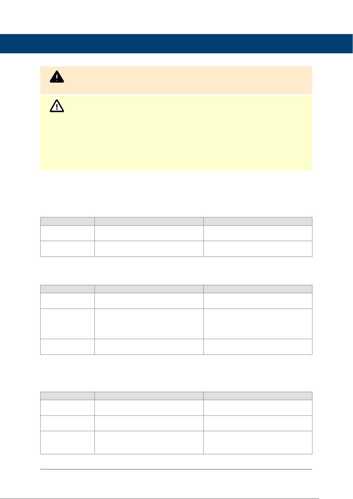
7. Has the piping work been done correctly, as shown in the figures below?
Requirement Correct Incorrect
Install catchpot with the proper
diameter.
Diameter is too small.
Make sure the flow of
condensate is not obstructed.
Diameter is too small and inlet
protrudes into pipe interior.
To prevent rust and scale from
flowing into the product, the inlet
pipe should be connected 25 to
50 mm (1 to 2 in) above the
base of the T-pipe.
Rust and scale flow into the
trap with the condensate.
When installing on the blind
end, make sure the flow of
condensate is not obstructed.
Condensate collects in the
pipe.
6
Operation
Principles of air and condensate discharge:
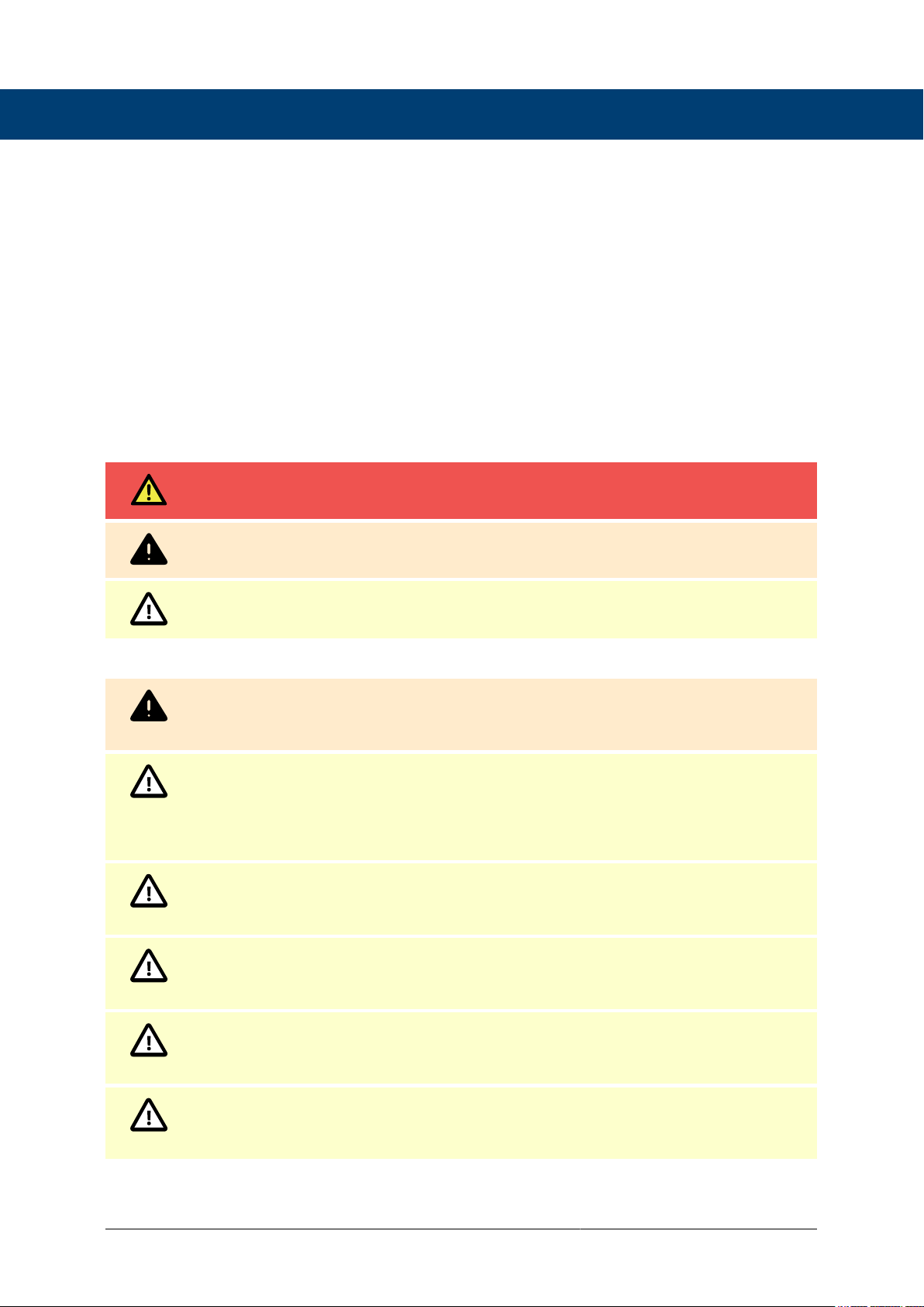
1. Start-up air and cold condensate discharge
At start-up, before steam is supplied, the trap is cold so the X-element is contracted and
the air vent valve (A) is open. This allows for the rapid discharge of air through the air vent
valve (A) and cold condensate through the orifice (B), when steam is first supplied to the
system.
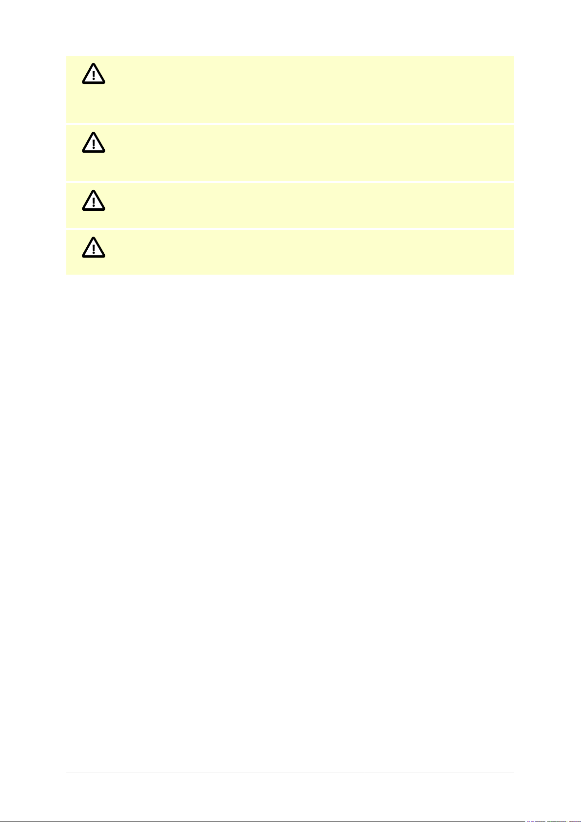
2. Condensate discharge
After the discharge of initial air and cold condensate, the heat of the inflowing steam and
condensate causes the X-element to expand, closing the air vent valve (A). The rising
condensate level causes the float to rise due to buoyancy, opening the orifice (B) and
allowing condensate to be discharged.
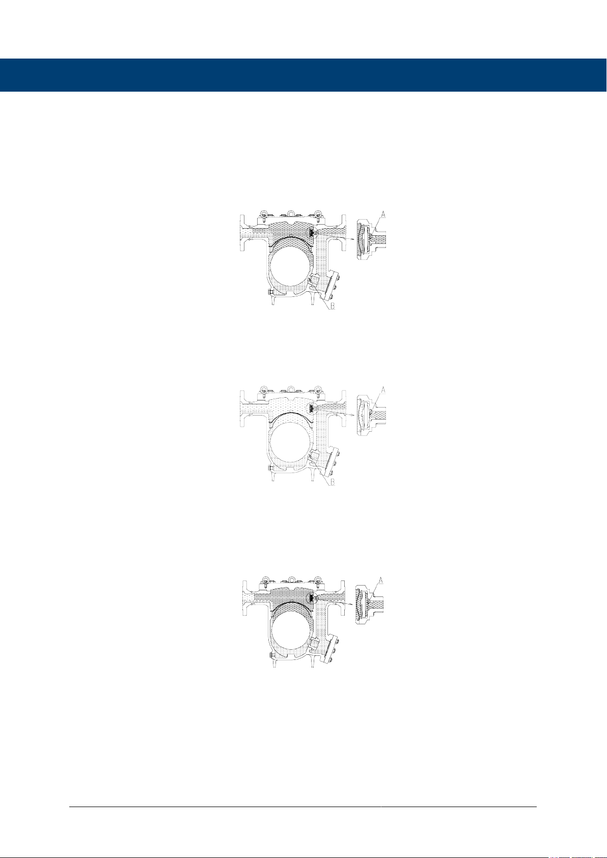
3. Hot air discharge
Should hot air flow into the trap with the steam during normal operation, the temperature
of the X-element drops, causing it to momentarily contract and open the air vent valve
(A), which allows for the rapid discharge of the air. After the air is discharged and steam
contacts the X-element, the temperature will increase causeing the air vent valve (A) to
close.
4. Discharge of large quantities of condensate
Increases in the condensate inflow rate cause the condensate level in the trap to rise.
The float consequently rises and enlarges the opening of the orifice (B), allowing more
condensate to be discharged. If condensate flows in at a faster rate than it discharges
through the orifice (B), the temperature of the X-element drops, causing it to momentarily
contract and open the air vent valve (A), which allows for the rapid discharge of the
condensate through both (A) and (B). In this manner, continuous condensate discharge
occurs while the opening size of the orifice varies depending on the condensate flow rate.
7
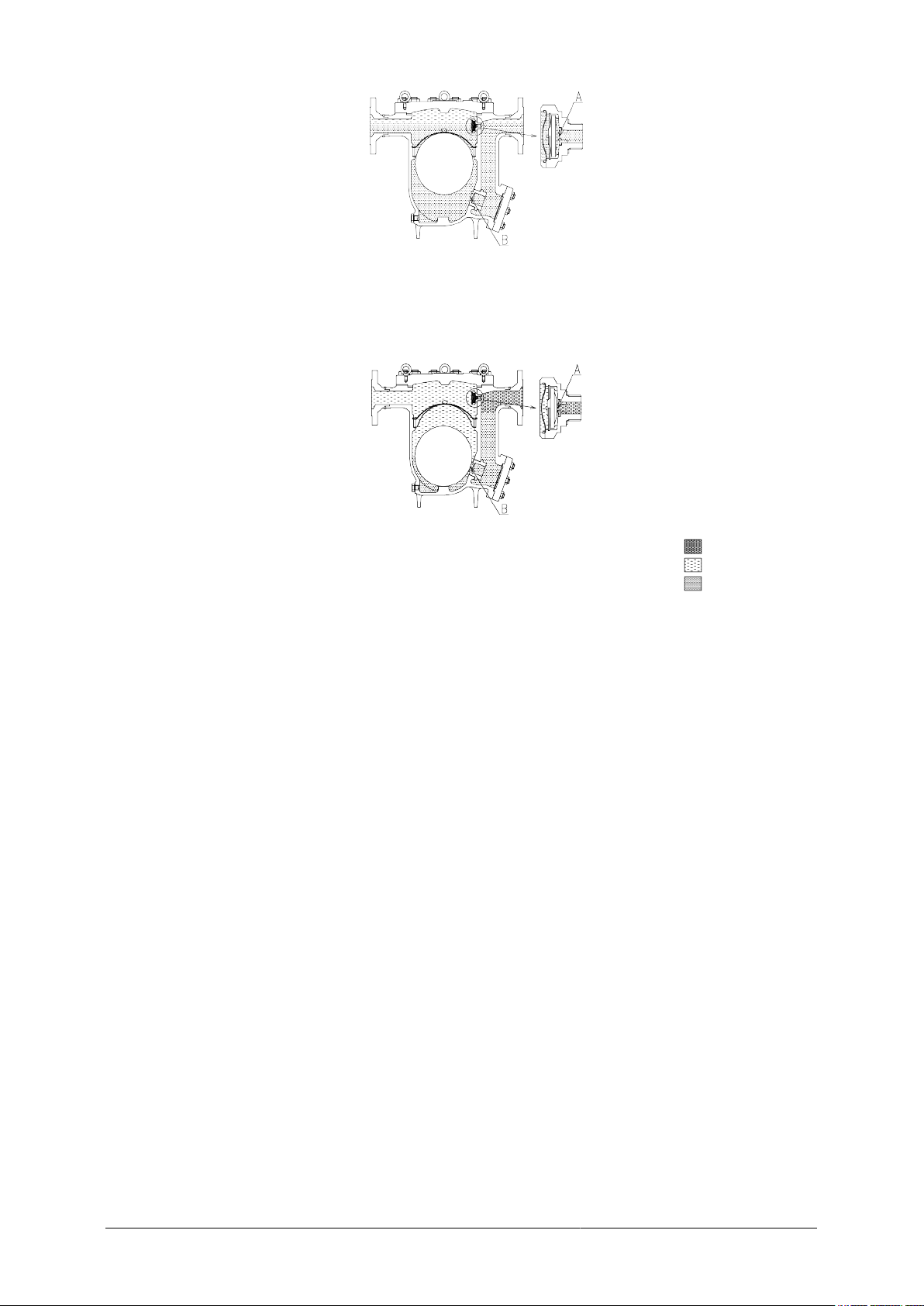
5. Closed position
When the condensate flow rate decreases, the X-element expands due to the heat of
the steam, closing the air vent valve (A). In addition, the float falls as condensate is
discharged, closing off the orifice (B). A water seal is maintained at all times over the
orifice (B) to prevent steam loss.
Air
Steam
Condensate
8

Specifications
Caution
Install properly and DO NOT use this product outside the recommended operating
pressure, temperature and other specification ranges. Improper use may result in such
hazards as damage to the product or malfunctions that may lead to serious accidents. Local
regulations may restrict the use of this product to below the conditions quoted.
DO NOT use this product in excess of the maximum operating pressure differential. Such
use could make discharge impossible (blocked).
Use only under conditions in which no freeze-up will occur. Freezing may damage the unit,
leading to fluid discharge, which may different cause burns or other injury.
A Model
B Nominal Diameter
C Maximum Allowable Pressure (PMA) 01
D Maximum Allowable Temperature (TMA) 01
E Maximum Operating Temperature (TMO)
F Maximum Differential Pressure (PMX)
G Production Lot No.
H Valve No. 02
01Maximum allowable pressure (PMA) and maximum allowable temperature (TMA) are PRESSURE
SHELL DESIGN CONDITIONS, NOT OPERATING CONDITIONS.
02Valve No. is displayed for products with options. This item is omitted from the nameplate when there
are no options.
9

Configuration
No Part Name Maintenance
Kit Repair Kit X-element
Kit Float
1 Body
2 Cover
3 Float ✓
4 Orifice ✓
5 Orifice Gasket ✓ ✓
6 Outlet Cover Gasket ✓ ✓
7 Screen ✓
8 Screen Holder
9 Snap Ring
10 Cover Gasket ✓ ✓
11 Cover Bolt
12 Cover Nut
13 Outlet Cover
14 Outlet Cover Bolt
15 Outlet Cover Nut
16 X-element Case ✓
17 Snap Ring ✓
18 X-element Screen ✓
19 Spring Clip ✓
20 X-element ✓
21 Air Vent Valve Seat ✓
22 X-element Case Gasket ✓ ✓ ✓
23 Nameplate
24 Screen Holder Retainer
25 Eye Bolt
10

No Part Name Maintenance
Kit Repair Kit X-element
Kit Float
26 Flange/Socket
27 Drain Plug Gasket ✓ ✓
28 Drain Plug
11

Installation
Caution
Install properly and DO NOT use this product outside the recommended operating
pressure, temperature and other specification ranges. Improper use may result in such
hazards as damage to the product or malfunctions that may lead to serious accidents. Local
regulations may restrict the use of this product to below the conditions quoted.
Use hoisting equipment for heavy objects (weighing approximately 20 kg (44 lb) or more).
Failure to do so may result in back strain or other injury if the object should fall.
Use the eye bolts for removing the cover only; DO NOT use the eye bolts for hoisting the
product. Eye bolts may break under strain, possibly resulting in serious injury.
Take measures to prevent people from coming into direct contact with product outlets.
Failure to do so may result in burns or other injury from the discharge of fluids.
Installation, inspection, maintenance, repairs, disassembly and adjustment and valve opening/
closing should be carried out only by trained maintenance personnel.
1. Before installation, be sure to remove all protective seals.
2. Before installing the product, blow out the inlet piping to remove any piping scraps, dirt and
oil. Close the inlet valve after blowdown.
3. When hoisting the product, hang a wire around the inlet/outlet as close to the body as
possible.
4. Install the product so the arrow on the body is pointing in the direction of flow.
5. The product should be inclined no more than 5º horizontally and front-to-back.
6. Install a condensate outlet valve and outlet piping.
7. Open the inlet and outlet valves and ensure that the product functions properly.
If there is a problem, determine the cause using the "Troubleshooting" section in this manual.
Tolerance Angle for Installation: 5°
Make sure the product is installed with the raised TLV lettering on the body horizontal.
12

Maintenance
Caution
Take measures to prevent people from coming into direct contact with product outlets.
Failure to do so may result in burns or other injury from the discharge of fluids.
Be sure to use only the recommended components when repairing the product, and NEVER
attempt to modify the product in any way. Failure to observe these precautions may result in
damage to the product and burns or other injury due to malfunction or the discharge of fluids.
Operational Check
A visual inspection of the following items should be done on a daily basis to determine
whether the product is operating properly or has failed. Periodically (at least biannually) the
operation should also be checked by using diagnostic equipment such as a stethoscope,
thermometer, TLV Pocket TrapMan or TLV TrapMan.
If the product should fail, it may cause damage to piping and equipment, resulting in faulty or
low quality products or losses due to steam leakage.
Normal: Condensate is discharged continuously, together with flash steam, and the
sound of flow can be heard. If there is very little condensate, there is almost
no sound of flow.
Blocked
(Discharge
Impossible):
No condensate is discharged. The product is quiet and makes no noise, and the
surface temperature of the product is low.
Blowing: Live steam continually flows from the outlet and there is a continuous metallic
sound.
Steam Leakage: Live steam is discharged through the trap outlet together with condensate,
accompanied by a high-pitched sound.
(When conducting a visual inspection, flash steam is sometimes mistaken for steam leakage.
For this reason, the use of a steam trap diagnostic instrument such as TLV TrapMan in
conjunction with the visual inspection is highly recommended.)
Flash Steam Live Steam Leakage
Parts Inspection
When parts have been removed, or during periodic inspections, use the following table to
inspect the parts and replace any that are found to be defective.
Procedure
Gaskets: Check for warping or scratches
Screen: Check for clogging or corrosion
X-element: Check for scratches
Valve Seat: Check for scratches
13

Float: Check for scratches or dents
Orifice Opening: Check for dirt, oil film, wear or scratches
14
Disassembly/Reassembly
Warning
NEVER apply direct heat to the float. The float may explode due to increased internal pressure,
causing accidents leading to serious injury or damage to property and equipment.
Caution
Use hoisting equipment for heavy objects (weighing approximately 20 kg (44 lb) or more).
Failure to do so may result in back strain or other injury if the object should fall.
Use the eye bolts for removing the cover only; DO NOT use the eye bolts for hoisting the
product. Eye bolts may break under strain, possibly resulting in serious injury.
When disassembling or removing the product, wait until the internal pressure equals
atmospheric pressure and the surface of the product has cooled to room temperature.
Disassembling or removing the product when it is hot or under pressure may lead to discharge of
fluids, causing burns, other injuries or damage.
Use the following procedures to remove components. Use the same procedures in reverse to
reassemble. (Installation, inspection, maintenance, repairs, disassembly, adjustment and valve
opening/closing should be carried out only by trained maintenance personnel.)
Drain Plug
Part Name During Disassembly During Reassembly
Drain Plug 28 Remove with a socket wrench Consult the table of tightening torques
and tighten to the proper torque
Drain Plug
Gasket 27 Remove the gasket and clean sealing
surfaces Replace with a new gasket; coat
surfaces with anti-seize
Detaching/Reattaching the Cover
Part Name During Disassembly During Reassembly
Cover Nut 12 Remove with a socket wrench Consult the table of tightening torques
and tighten to the proper torque
Cover 2 Use all four (4) eye bolts to lift up and
off, making sure to evenly distribute
the weight of the cover among them
Make sure there are no pieces of the
old gasket left on the sealing surfaces
of the body and cover, align the arrows
on the body and cover and reattach
Cover Gasket 10 Remove the gasket and clean sealing
surfaces Replace with a new gasket
Disassembly/Reassembly of the X-element Case and Components Inside the
X-element Case
Part Name During Disassembly During Reassembly
X-element Case
16 Remove with a box wrench Consult the table of tightening torques
and tighten to the proper torque
X-element Case
Gasket 22 Remove the gasket and clean sealing
surfaces Replace with a new gasket; coat
surfaces with anti-seize
Snap Ring 17
(X-element Case
16)
Pinch the insides together and remove
from the X-element case Insert securely into the guide in the
X-element case
15

Part Name During Disassembly During Reassembly
X-element Screen
18 Remove from the X-element case Insert after making sure of the correct
orientation
Spring Clip 19
(X-element 20) Pinch the insides together and remove
from the X-element case Insert securely into the guide in the
X-element case
X-element 20 Remove from the X-element case Insert after making sure of the correct
orientation
Note
Do not attempt to remove the press-in air vent valve seat from the X-element case.
Disassembly/Reassembly of Components Inside the Body
Note
The X-element case must be removed before the float can be removed.
Part Name During Disassembly During Reassembly
Snap Ring 9 Pinch insides together and remove
from the body Insert securely into the groove in the
body
Screen 7 Remove by grasping the wire ring and
lifting straight up and out Set the screen on the screen holder
and screen holder retainer and insert
as far as the snap ring groove
Screen Holder
Retainer 24 Remove without bending Place on the screen holder without
tilting
Screen Holder 8 Remove without bending Place on the ledge inside the body,
making sure the rounded side is on to
Float 3 Remove, being careful not to scratch
the polished surface Insert, being careful not to scratch the
polished surface
Outlet Cover Nut
15 Remove with a socket wrench Consult the table of tightening torques
and tighten to the proper torque
Outlet Cover 13 Remove, being careful not to scratch
the gasket sealing surfaces Make sure there are no pieces of the
old gasket left on the sealing surfaces
of the body and cover
Outlet Cover
Gasket 6 Remove the gasket and clean sealing
surfaces Replace with a new gasket
Orifice 4 Remove with a socket wrench Consult the table of tightening torques
and tighten to the proper torque
Orifice Gasket 5 Remove the gasket and clean sealing
surfaces Replace with a new gasket: coat
surfaces with anti-seize
Table of Tightening Torques
Part Names Torque (N‧m) Distance Across Flats (mm)
Orifice 4 1000 60
Outlet Cover Nut 15 160 24
Cover Nut 12 450 36
X-element Case 16 150 50
Drain Plug 28 100 26
16
Note
• Coat all threaded portions and valve seat gasket with anti-seize.
• If drawings or other special documentation were supplied for the product, any torque given there
takes precedence over values shown here.
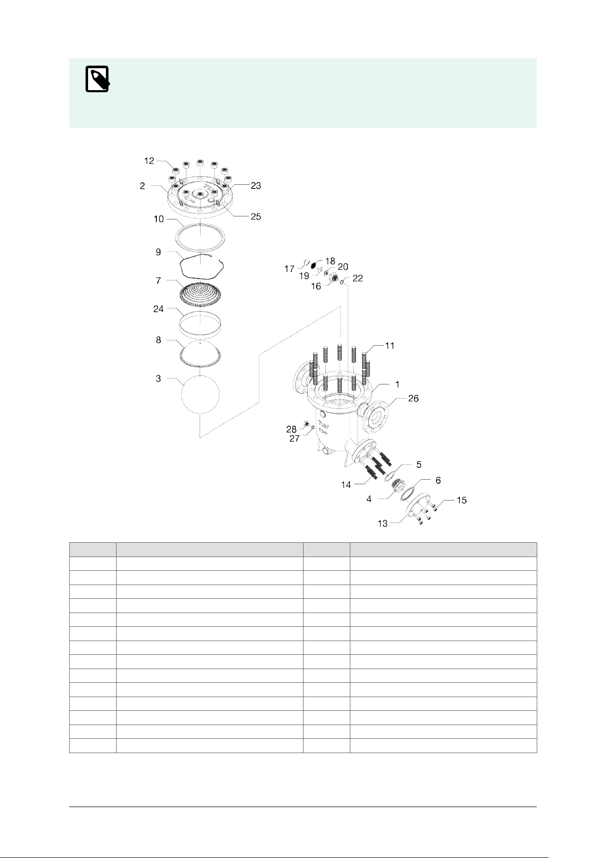
Exploded View
No. Part Name No. Part Name
1 Body 15 Outlet Cover Nut
2 Cover 16 X-element Case
3 Float 17 Snap Ring
4 Orifice 18 X-element Screen
5 Orifice Gasket 19 Spring Clip
6 Outlet Cover Gasket 20 X-element
7 Screen 21 Air Vent Valve Seat
8 Screen Holder 22 X-element Case Gasket
9 Snap Ring 23 Nameplate
10 Cover Gasket 24 Screen Holder Retainer
11 Cover Bolt 25 Eye Bolt
12 Cover Nut 26 Flange (Socket)
13 Outlet Cover 27 Drain Plug Gasket
14 Outlet Cover Bolt 28 Drain Plug
17
Instructions for Plug/Holder Disassembly and
Reassembly
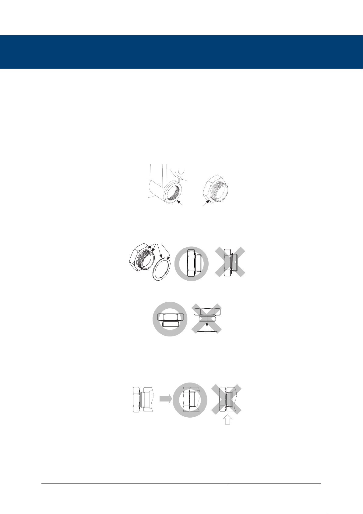
The seal on the threaded plugs/holders found on TLV products is formed by a flat metal
gasket. There are various installation orientations for the gaskets, such as horizontal, diagonal
and downward, and the gasket may be pinched in the thread recesses during assembly.
Instructions for Disassembly and Reassembly
1. Remove the plug/holder using a tool of the specified size (distance across flats).
2. The gasket should not be reused. Be sure to replace it with a new gasket.
3. Clean the gasket surfaces of the plug/holder and the product body using a rag and/or
cleaning agents, then check to make sure the surfaces are not scratched or deformed.
4. Coat both the gasket surface of the plug/holder and the threads of the plug/holder with
anti-seize, then press the gasket onto the center of the gasket surface of the plug/holder,
making sure the anti-seize affixes the gasket tightly to the plug/holder. Check to make sure
the gasket is not caught in the recesses of the threads.
5. Hold the plug/holder upside down to make sure that the anti-seize makes the gasket stick
to the plug/holder even when the plug/holder is held upside down.
6. Screw the plug/holder by hand into the product body while making sure that the gasket
remains tightly affixed to the center of the gasket surface of the plug/holder. Make sure
the entire gasket is making contact with the gasket surface of the product body. It is
important at this point to make sure the gasket is not pinched in the thread recesses of the
plug/holder.
7. Tighten the plug/holder to the proper torque.
8. Next, begin the supply of steam and check to make sure there is no leakage from the
part just tightened. If there is leakage, immediately close the inlet valve and, if there is a
bypass valve, take the necessary steps to release any residual pressure. After the surface
of the product cools to room temperature, repeat the procedure beginning from step 1.
18
Troubleshooting
Warning
NEVER apply direct heat to the float. The float may explode due to increased internal pressure,
causing accidents leading to serious injury or damage to property and equipment.
Caution
When disassembling or removing the product, wait until the internal pressure equals
atmospheric pressure and the surface of the product has cooled to room temperature.
Disassembling or removing the product when it is hot or under pressure may lead to discharge of
fluids, causing burns, other injuries or damage.
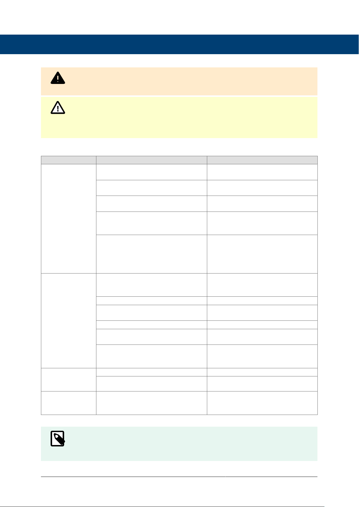
If the product fails to operate properly, use the following table to locate the cause and remedy.
Problem Cause Remedy
No condensate
is discharged
(blocked) or
discharge is poor
The float is damaged or filled with
condensate Replace with a new float
The orifice opening, screen or piping
are clogged with rust and scale Clean parts
The X-element is scratched or
damaged Replace with a new X-element
Steam-locking has occurred Perform a bypass blowdown or close
the product inlet valve and allow the
product to cool
The product operating pressure
exceeds the maximum specified
pressure, or whether there is
insufficient pressure differential
between the product inlet and outlet
Compare specifications and actual
operating conditions
Steam is
discharged or
leaks from the
outlet
(blowing)
(steam leakage)
Build-up on the seating surface of
the orifice or rust and scale build-up
beneath the float
Clean parts
Scratches on the orifice Replace with a new orifice
The float is misshapen or has a build-
up Clean or replace with a new float
Improper installation orientation Correct the installation
Product vibration Lengthen the inlet piping and fasten it
securely
The air vent valve seating area of the
X-element and/or air vent valve seat
have a build-up or are scratched
Clean the air vent valve seating area
of the X-element and/or air vent valve
seat or replace the X-element unit
Steam is leaking
from a place other
than the outlet
Gasket deterioration or damage Replace with new gasket(s)
Improper tightening torques were used Tighten to the proper torque
Float frequently
becomes
damaged
Water hammer has occurred Study and correct the piping
Note
When replacing parts with new, use the parts list for reference, and replace with parts from the
Maintenance Kit, Repair Kit, etc. Please note that replacement parts are only available as part of a
replacement parts kit.
19

TLV EXPRESS LIMITED WARRANTY
Subject to the limitations set forth below, TLV CO., LTD., a Japanese corporation (“TLV”),
warrants that products which are sold by it, TLV International Inc. (“TII”) or one of its
group companies excluding TLV Corporation (a corporation of the United States of America),
(hereinafter the “Products”) are designed and manufactured by TLV, conform to the
specifications published by TLV for the corresponding part numbers (the “Specifications”)
and are free from defective workmanship and materials. The party from whom the Products
were purchased shall be known hereinafter as the “Seller”. With regard to products or
components manufactured by unrelated third parties (the “Components”), TLV provides no
warranty other than the warranty from the third party manufacturer(s), if any.
Exceptions to Warranty
This warranty does not cover defects or failures caused by:
1. improper shipping, installation, use, handling, etc., by persons other than TLV, TII or TLV
group company personnel, or service representatives authorized by TLV; or
2. dirt, scale or rust, etc.; or
3. improper disassembly and reassembly, or inadequate inspection and maintenance by
persons other than TLV or TLV group company personnel, or service representatives
authorized by TLV; or
4. disasters or forces of nature or Acts of God; or
5. abuse, abnormal use, accidents or any other cause beyond the control of TLV, TII or TLV
group companies; or
6. improper storage, maintenance or repair; or
7. operation of the Products not in accordance with instructions issued with the Products or
with accepted industry practices; or
8. use for a purpose or in a manner for which the Products were not intended; or
9. use of the Products in a manner inconsistent with the Specifications; or
10. use of the Products with Hazardous Fluids (fluids other than steam, air, water, nitrogen,
carbon dioxide and inert gases (helium, neon, argon, krypton, xenon and radon)); or
11. failure to follow the instructions contained in the TLV Instruction Manual for the Product.
Duration of Warranty
This warranty is effective for a period of one (1) year after delivery of Products to the first end
user. Notwithstanding the foregoing, asserting a claim under this warranty must be brought
within three (3) years after the date of delivery to the initial buyer if not sold initially to the first
end user.
ANY IMPLIED WARRANTIES NOT NEGATED HEREBY WHICH MAY ARISE BY
OPERATION OF LAW, INCLUDING THE IMPLIED WARRANTIES OF MERCHANTABILITY
AND FITNESS FOR A PARTICULAR PURPOSE AND ANY EXPRESS WARRANTIES NOT
NEGATED HEREBY, ARE GIVEN SOLELY TO THE INITIAL BUYER AND ARE LIMITED IN
DURATION TO ONE (1) YEAR FROM THE DATE OF SHIPMENT BY THE SELLER.
Exclusive Remedy
THE EXCLUSIVE REMEDY UNDER THIS WARRANTY, UNDER ANY EXPRESS
WARRANTY OR UNDER ANY IMPLIED WARRANTIES NOT NEGATED HEREBY
(INCLUDING THE IMPLIED WARRANTIES OF MERCHANTABILITY AND FITNESS FOR A
PARTICULAR PURPOSE), IS REPLACEMENT; PROVIDED: (a) THE CLAIMED DEFECT IS
20
Table of contents
Other TLV Industrial Equipment manuals


Popular Industrial Equipment manuals by other brands

Mayr
Mayr EAS-smartic 484.XX5 Series Installation and operational instructions

BVA Hydraulics
BVA Hydraulics HDG15002 instruction manual

Jet
Jet 190918 operating instructions

Jetting
Jetting V0 HD 18 V User's guide & safety manual

Taylor Tools
Taylor Tools Bronco 260P-G2 owner's manual

Rexnord
Rexnord FALK HF132 Installation & maintenance

Mitsubishi Electric
Mitsubishi Electric CNC MELDASMAGIC64 Connection manual

SCHUNK
SCHUNK PGH Series Assembly and operating manual

SUHNER MACHINING
SUHNER MACHINING BEW 3 Technical document

GSi
GSi 40 Series Assembly manual

Bondura
Bondura 6.6 assembly and inspection manual

Honeywell
Honeywell TA3840 Maintenance manual


