TLV BT3N User manual

172-65162M-03 (BT3N/MBT3N/PBT3N) 5 July 2013
Manufacturer
Kakogawa, Japan
is approved by LRQA LTD. to ISO 9001/14001
Bypass Blowdown Steam Trap
BT3N / MBT3N / PBT3N
Copyright © 2013 by TLV CO., LTD.
All rights reserved

1
Contents
Introduction ........................................................................ 1
172-65162M-03 (BT3N/MBT3N/PBT3N) 5 Jul 2013
4
5
6
8
11
15
16
19
24
27
Safety Considerations ........................................................ 2
Checking the Piping ...........................................................
Operation ...........................................................................
Specifications .....................................................................
Configuration......................................................................
Installation and Operation ................................................
Manual Operation.............................................................
Maintenance.....................................................................
Disassembly / Reassembly ..............................................
Troubleshooting ...............................................................
Product Warranty .............................................................
Introduction
Thank you for purchasing the Bypass Blowdown Steam Trap.
This product has been thoroughly inspected before being shipped from the factory.
When the product is delivered, before doing anything else, check the specifications
and external appearance to make sure nothing is out of the ordinary. Also be sure to
read this manual carefully before use and follow the instructions to be sure of using
the trap properly.
The Bypass Blowdown Steam Trap features a combination of: the most reliable
of steam traps, the free float; a compact ball valve, with superior long-lasting sealing
properties; and an actuator unit (electric, pneumatic).
The following models are contained in this manual:
BT3N: Steam trap with an integrated compact bypass blowdown ball valve with a
manual operation handle
MBT3N: Steam trap with an integrated compact bypass blowdown ball valve with an
electric actuator
PBT3N: Steam trap with an integrated compact bypass blowdown ball valve with a
pneumatic actuator
If detailed instructions for special order specifications or options not contained in this
manual are required, please contact for full details.
This instruction manual is intended for use with the model(s) listed on the front cover.
It is necessary not only for installation but for subsequent maintenance,
disassembly/reassembly and troubleshooting. Please keep it in a safe place for future
reference.

2
Safety Considerations
•Read this section carefully before use and be sure to follow the instructions.
•Installation, inspection, maintenance, repairs, disassembly, adjustment and valve
opening/closing should be carried out only by trained maintenance personnel.
•The precautions listed in this manual are designed to ensure safety and prevent
equipment damage and personal injury. For situations that may occur as a result
of erroneous handling, three different types of cautionary items are used to
indicate the degree of urgency and the scale of potential damage and danger:
DANGER, WARNING and CAUTION.
•The three types of cautionary items above are very important for safety: be sure to
observe all of them as they relate to installation, use, maintenance, and repair.
Furthermore, TLV accepts no responsibility for any accidents or damage occurring
as a result of failure to observe these precautions.
Symbols
Indicates a DANGER, WARNING or CAUTION item.
DANGE
R
Indicates an urgent situation which poses a threat of death or
serious injury
WARNING Indicates that there is a potential threat of death or serious injury
CAUTION Indicates that there is a possibility of injury or equipment / product
damage
WARNING
NEVER apply direct heat to the float.
The float may explode due to increased internal pressure, causing
accidents leading to serious injury or damage to property and
equipment.
Install properly and DO NOT use this product outside the
recommended operating pressure, temperature and other
specification ranges.
Improper use may result in such hazards as damage to the product or
malfunctions that may lead to serious accidents. Local regulations may
restrict the use of this product to below the conditions quoted.
DO NOT use this product in excess of the maximum operating
pressure differential.
Such use could make discharge impossible (blocked).
Take measures to prevent people from coming into direct
contact with product outlets.
Failure to do so may result in burns or other injury from the discharge
of fluids.
CAUTION
When disassembling or removing the product, wait until the
internal pressure equals atmospheric pressure and the
surface of the product has cooled to room temperature.
Disassembling or removing the product when it is hot or under
pressure may lead to discharge of fluids, causing burns, other
injuries or damage.
Safety cautions continued on next page
172-65162M-03 (BT3N/MBT3N/PBT3N) 5 Jul 2013

3
Be sure to use only the recommended components when
repairing the product, and NEVER attempt to modify the
product in any way.
Failure to observe these precautions may result in damage to the
product and burns or other injury due to malfunction or the
discharge of fluids.
Do not use excessive force when connecting threaded pipes
to the product.
Over-tightening may cause breakage leading to fluid discharge,
which may cause burns or other injury.
Use only under conditions in which no freeze-up will occur.
Freezing may damage the product, leading to fluid discharge,
which may cause burns or other injury.
Use only under conditions in which no water hammer will
occur.
The impact of water hammer may damage the product, leading to
fluid discharge, which may cause burns or other injury.
Do not stand on or apply body weight to the handle.
The handle may break, resulting in injury or other accidents.
Make sure the power supply is OFF before carrying out work
on the wiring or inspections involving disassembly.
If such work is carried out with the power on, there is a danger that
equipment may malfunction or electric shock may occur, leading to
injury or other accidents.
Make sure that wiring work requiring a special license is
carried out only by qualified personnel.
If carried out by unqualified personnel, overheating or short circuits
leading to injury, fires, damage or other accidents may occur.
CAUTION
When using this product, NEVER stand close to, or leave
tools anywhere near moving parts such as the shaft.
Contact with moving parts or objects becoming caught in moving
parts could lead to injury, damage or other accidents.
172-65162M-03 (BT3N/MBT3N/PBT3N) 5 Jul 2013

4
Checking the Piping
Use only under conditions in which no water hammer will occur. The
impact of water hammer may damage the product, leading to fluid
discharge, which may cause burns or other injury.
CAUTION
Check to make sure that the pipes to be connected to the trap have been installed
properly.
1. Is the pipe diameter suitable?
2. Has sufficient space been secured for maintenance? (Refer to step 3. in the
“Installation” section.)
3. Are the inlet and outlet connections on the same horizontal plane?
4. Have maintenance valves been installed at the inlet and outlet? If the outlet is
subject to back pressure, has a check valve (TLV-CK) been installed?
5. Is the inlet pipe as short as possible, with as few bends as possible, and installed
so the liquid will flow naturally down into the trap?
6. Has the piping work been done with the proper methods, shown in the figures
below?
Requirement Correct Incorrect
Install catchpot with the
proper diameter.
Diameter is too small.
Make sure the flow of
condensate is not obstructed.
Diameter is too small and inlet
protrudes into pipe interior.
To prevent rust and scale
from flowing into the trap, the
inlet pipe should be
connected 25 - 50 mm above
the base of the T-pipe.
Rust and scale flow into the
trap with the condensate.
When installing on the blind
end, make sure the flow of
condensate is not obstructed.
Condensate collects in the
pipe.
172-65162M-03 (BT3N/MBT3N/PBT3N) 5 Jul 2013

5
Operation
1. At start-up, the bypass blowdown valve can be
opened to allow a large quantity of condensate
to be rapidly discharged, minimizing the time
required for the unit to warm up. The bimetal
holds the float away from the orifice so that
initial air in the trap chamber is also
discharged.
Bypass Valve:
Opened
2. After the blowdown operation ends, the
bimetal strip retracts and the valve closes, the
float automatically adjusts the valve opening in
response to the fluctuation in load, and the
condensate is continuously discharged –no
condensate will accumulate ahead of the
steam trap.
Bypass Valve:
Closed
3. When the amount of condensate flowing into
the chamber decreases, the float gradually
closes the orifice. Steam leakage is prevented
through the use of a 3-point seating design
and the water sealing of the valve. Normally
the bimetal remains retracted and has no
effect on the operation of the float, but if air
should accumulate in the trap and the
temperature drops, it extends, forcing the float
up and the air is automatically vented.
Air, Condensate
Steam
Condensate
172-65162M-03 (BT3N/MBT3N/PBT3N) 5 Jul 2013

6
Specifications
Install properly and DO NOT use this product outside the recommended
operating pressure, temperature and other specification ranges.
Improper use may result in such hazards as damage to the product or
malfunctions which may lead to serious accidents. Local regulations
may restrict the use of this product to below the conditions quoted.
CAUTION
DO NOT use this product in excess of the maximum operating pressure
differential; such use could make discharge impossible (blocked).
CAUTION
Use only under conditions in which no freeze-up will occur. Freezing
may damage the product, leading to fluid discharge, which may cause
burns or other injury.
CAUTION
Steam Trap Body
Refer to the product nameplate for detailed specifications.
Model
Maximum Allowable
Temperature* (TMA)
Maximum Allowable
Pressure*
Nominal Diameter
Maximum Operating
Temperature
Maximum Differential
Pressure
Valve No.**
Serial Number
* Maximum allowable pressure (PMA) and maximum allowable temperature (TMA) are
PRESSURE SHELL DESIGN CONDITIONS, NOT OPERATING CONDITIONS.
** Valve No. is displayed for products with options. This item is omitted from the nameplate
when there are no options.
MBT3N: Motor Unit
Motor Type Reversible motor (condenser run type single-phase induction motor)
Power Consumption 52 VA (100 - 110 V), 62 VA (200 – 220 V)
Control System ON-OFF (fully open/fully closed)
Overload Protection Built-in thermal protector 120±5 °C
Direction of Rotation 90° reciprocating
Open/Close Time
(90° rotation)
3.5 seconds/50 Hz
3.0 seconds/60 Hz
Water Resistance Rainproof
Manual Override Possible when the power is OFF
Ambient Temp. Range
and Operation Cycles
(within 1 cm of the trap
cover)
172-65162M-03 (BT3N/MBT3N/PBT3N) 5 Jul 2013
Open Closed
AB
Operation Cycle*
A: Closed-to-open
B: Open-to-closed
1000
500
200
100
50
20
15
020 40 60 70 80
1.0 MPaG Steam
0.5 MPaG Steam
Operation Cycles (sec.)
Ambient Temp. (°C)
*“Operation cycle” is the interval
between the motor stop at the end
of one open or close operation
and the motor start at the
beginning of the next.
Example: When the ambient temperature is 40 °C, and the medium in use
is steam at 0.5 MPaG, allow for a cycle operation interval of at
least 36 seconds. When the cycle operation interval is less than
36 seconds, a thermal protector will prevent the motor unit from
operating until it cools down sufficiently.
(1 MPa = 10.197 kg/cm2)

7
PBT3N: Actuator Unit
Actuator Type Vane rotary actuator
Air Supply Pressure 0.3 - 1.0 MPaG
Air Supply Port Size Rc(PT)1/8
Control System ON-OFF (fully open/fully closed) reciprocating
Open/Close Time
(90° rotation) 0.09 - 0.8 seconds
Actuator Capacity 42 cm3
Ambient Temp. Range 60 °C or lower
Water Resistance Rainproof
Manual Override Possible in absence of motive pressure
Air Consumption
(Graph represents
consumption for one
reciprocating cycle)
1.5
1.0
0.5
00.4 0.6 0.8 1.0
(kg/cm
2
G)
Air Supply Pressure (MPaG)
46810
Air Consumption (N litre)
(1 MPa = 10.197 kg/cm2)
172-65162M-03 (BT3N/MBT3N/PBT3N) 5 Jul 2013

8
Configuration
BT3N
Part No. 29 (bushing)
attached only for
sizes 15 & 20 mm
Enlarged view of the
valve section
Enlarged view of the
orifice area
NOTE: Removing the handle or locknut causes degradation of the gland section seal. Do not
remove the handle or locknut except when performing a disassembly inspection.
No. Name No. Name No. Name
1 Body 11 Nameplate 21 Disc Spring
2 Cover 12 Screen 22 Gland Packing
3 Float 13 Ball 23 Washer
4 Orifice 14 Outlet Valve Seat 24 Thrust Washer
5 Orifice Gasket 15 Inlet Valve Seat 25 Washer
6 Air Vent Strip (Bimetal) 16 Spindle
7 Screw & Spring Washer 17 Gland
26 O-ring (Inlet/Outlet
Valve Seat)
8 Cover Gasket 18 Gland Gasket 27 Valve Holder
9 Cover Bolt 19 Handle 28 Locknut
10 Orifice Plug 20 Disc Spring 29 Bushing*
* Included only with 15 and 20 mm sizes.
172-65162M-03 (BT3N/MBT3N/PBT3N) 5 Jul 2013

9
MBT3N
Enlarged view of the
valve section
Enlarged view of the
orifice area
No. Name No. Name No. Name
1 Body 13 Ball 25 Seal
2 Cover 14 Outlet Valve Seat 26 Washer
3 Float 15 Inlet Valve Seat
4 Orifice 16 Spindle
27
O-ring (Inlet/Outlet
Valve Seat )
5 Orifice Gasket 17 Gland Holder 28 Valve Holder
6 Air Vent Strip (Bimetal) 18 Gland Holder Gasket
7 Screw & Spring Washer 19 Gland Seat
29 Holder Screw
(Gland Holder)
8 Cover Gasket 20 Disc Spring 30 Bushing*
9 Cover Bolt 21 Disc Spring 31 Motor Unit
10 Orifice Plug 22 Gland Packing 32 Shaft Coupling
11 Nameplate 23 Washer
12 Screen 24 Guide Bushing
* Included only with 15 and 20 mm sizes.
172-65162M-03 (BT3N/MBT3N/PBT3N) 5 Jul 2013

10
PBT3N
Enlarged view of the
valve section
Enlarged view of the
orifice area
No. Name No. Name No. Name
1 Body 13 Ball 25 Seal
2 Cover 14 Outlet Valve Seat 26 Washer
3 Float 15 Inlet Valve Seat
4 Orifice 16 Spindle
27 O-ring (Inlet/Outlet
Valve Seat)
5 Orifice Gasket 17 Gland Holder 28 Valve Holder
6 Air Vent Strip (Bimetal) 18 Gland Holder Gasket
7 Screw & Spring Washer 19 Gland Seat
29 Holder Screw
(Gland Holder)
8 Cover Gasket 20 Disc Spring 30 Bushing*
9 Cover Bolt 21 Disc Spring 31 Actuator Unit
10 Orifice Plug 22 Gland Packing 32 Shaft Coupling
11 Nameplate 23 Washer
12 Screen 24 Guide Bushing
* Included only with 15 and 20 mm sizes.
172-65162M-03 (BT3N/MBT3N/PBT3N) 5 Jul 2013

11
Installation and Operation
Install properly and DO NOT use this product outside the recommended
operating pressure, temperature and other specifica tion ranges.
Improper use may result in such hazards as damage to the product or
malfunctions which may lead to serious accidents. Local regulations
may restrict the use of this product to below the conditions quoted.
CAUTION
Take measures to prevent people from comin
g
into direct contact with
product outlets. Failure to do so may result in burns or other injury from
the dischar
g
e of fluids.
CAUTION
Do not use excessive force when connectin
g
threaded pipes to the
product. Over-tightening may cause breakage leading to fluid
discharge, which may cause burns or other injury.
CAUTION
Do not stand on or apply body weight to the handle. The handle may
break, resulting in injury or other accidents.
CAUTION
Make sure the power supply switch is OFF before carrying out work on
the wiring or inspections involving disassembly.
If such work is carried out with the power on, there is a danger that
equipment may malfunction or electric shock may occur, leading to
injury or other accidents.
CAUTION
Make sure that wirin
g
work requirin
g
a special license is carried out by
qualified personnel.
If carried out by unqualified personnel, overheating or short circuits
lead in
g
to in
j
ur
y
, fires, dama
g
e or other accidents ma
y
occur.
CAUTION
Wh en u s in
g
this product, NEVER stand close to, or leave tools anywhere
near moving parts, such as the shaft.
Contact with moving parts or objects becoming caught in moving parts
cou ld le a d to i n
j
ur
y
, dama
g
e or other accidents.
CAUTION
Installation, inspection, maintenance, repairs, disassembly, adjustment and valve
opening/closing should be carried out only by trained maintenance personnel.
1. Before installation, be sure to remove all protective seals.
2. Before installing the trap, open the inlet valve and thoroughly blow out the piping
to remove any piping scraps, dirt and oil. Blowdown is possible after the product
has been installed, however it is recommended that you remove all dirt, oil, etc.
from the inlet piping before installation. Close the inlet valve after blowdown.
3. Confirm that sufficient maintenance space has been provided around the product.
100 mm
150 mm
25 mm 25 mm
100 mm
MBT3N
Motor Unit
PBT3N
Actuator Unit
4. Where the product is installed in a location that may be affected by radiant heat
from nearby heat-generation, install a device to block the radiant heat, such as a
protective plate.
5. 15 mm and 20 mm sizes come with an additional bushing (refer to the
“Configuration” section). Be sure to screw the bushing or 25mm diameter piping to
the body only up to a point where at least 15 mm remain protruding from the
connecting screw. Over-tightening may cause breakage.
172-65162M-03 (BT3N/MBT3N/PBT3N) 5 Jul 2013

12
6. Install the product so that the arrow on the product is pointing in the direction of
condensate flow.
7. The product should be inclined no more than 5° horizontally and front-to-back.
8. Install the condensate outlet valve and the outlet piping.
Tolerance Angle for Installation - 5°
Make sure the trap is installed with the raised lettering on the body horizontal.
BT3N: Operation
1. Turn the handle to a position perpendicular to the piping.
(The integrated ball valve will close, causing the product to function as a trap.)
Open the inlet and outlet valves slowly and check to make sure that the product
functions properly as a steam trap.
If there is a problem, determine the cause by using the “Troubleshooting” section in
this manual.
2. To use the bypass function, turn the handle to a position parallel to the piping.
(The integrated ball valve will open.)
3. Return the handle to a position perpendicular to the piping to stop using the bypass
function.
(The integrated ball valve will close, causing the product to function as a trap.)
4. The integrated ball valve should be closed when the product is used as a trap.
NOTE: Operate the bypass valve (ball valve) in only the fully open or fully closed
positions. Operation in an intermediate position will damage the valve seat
and may lead to leaking of the valve.
172-65162M-03 (BT3N/MBT3N/PBT3N) 5 Jul 2013

13
MBT3N: Wiring/Operation
1. Connect the ON/OFF control switch as follows:
When the control switch is ON, the valve will open; when it is OFF, the valve will
close.
2. If connected to the yellow wire, a pilot lamp will light when the valve is open; if to
the brown, a pilot lamp will light when the valve is closed.
3. When checking the operation of the motor unit before installation, keep fingers well
clear of the bypass blowdown valve section.
Y yellow
BR brown
Rred
BK black
Wwhite
Ggreen
Y
BR
R
BK
W
G
Power AC
Electrical Ground
Control Switch
ON-open / OFF-closed
Lights when closed
Lights when open
PL
PL
4. Carry out an operational check of the motor under no-load conditions (no pressure)
before actual operation to ensure that the wiring is done properly.
You can check whether the valve is opened or closed by checking the orientation of
the flat surfaces on the shaft coupling at the base of the motor unit.(See p.15)
When the flat surfaces of the shaft coupling are lined up with the piping, the valve is
open; when they are perpendicular, the valve is closed.
5. Make sure the control switch is OFF at start-up.
(The integrated ball valve is closed, causing the product to function as a trap.)
Open the inlet and outlet valves slowly and check to make sure that the product
functions properly as a steam trap.
If there is a problem, determine the cause by using the “Troubleshooting” section of
this manual.
6. Turn the control switch ON to use the bypass function.
(The integrated ball valve will be open.)
7. Turn the control switch OFF to stop using the bypass function.
(The integrated ball valve will be closed.)
8. The integrated ball valve should be closed when the product is used as a trap.
172-65162M-03 (BT3N/MBT3N/PBT3N) 5 Jul 2013

14
PBT3N: Air Supply Piping/Operation
1. Use only clean air, which has been run through an air trap, filter, oiler, etc.
2. Make sure there is no foreign matter, particularly dirt or sealing tape, in the
pneumatic actuator.
3. The table below shows the relationship between the air supply and valve
opening/closing.
Port: A Port: B Valve
Supply Exhaust Open
Exhaust Supply Closed
4. When checking operation of the pneumatic actuator before installation, keep
fingers well clear of the bypass blowdown valve section.
Air Supply to Port A (air-to-open)
Air supply pressure: 0.3 – 1.0 MPaG
Air Supply to Port B (air-to-close)
Air supply pressure: 0.3 – 1.0 MPaG
Open/Closed Indicator
5. Carry out an operational check of the actuator under no-load conditions (no
pressure) before actual operation to ensure that the air is supplied properly.
The “Open/Closed” Indicator located in the lower part of the actuator indicates
whether the valve is opened/closed.
6. Make sure that the integrated ball valve is closed at start-up, causing the product to
function as a trap.
The state of the integrated ball valve can be confirmed using the “open/closed”
indicator. Open the inlet and outlet valves slowly and check to make sure that the
product functions properly. If there is a problem, determine the cause by using the
“Troubleshooting” section in this manual.
7. To use the bypass function, supply air through port A and exhaust the air in the
actuator through port B. The integrated ball valve will open.
8. To stop using the bypass function, supply air through port B and exhaust the air in
the actuator through port A. Integrated ball valve will close.
9. The integrated ball valve should be closed when the product is used as a trap.
172-65162M-03 (BT3N/MBT3N/PBT3N) 5 Jul 2013

15
Manual Operation
Take measures to prevent people from coming into direct contact with
product outlets. Failure to do so may result in burns or other injury from
the discharge of fluids.
CAUTION
MBT3N
1. Perform manual operation only after making sure that the power is OFF. Manual
operation cannot be performed when the power is ON. For safety, make sure the
power is OFF even during a power outage.
2. Grasp the flat surfaces of the shaft coupling at the base of the motor unit with a
wrench, and turn in the direction of the arrows. When the flat surfaces of the shaft
coupling are lined up with the piping, the valve is open; when they are
perpendicular, the valve is closed (distance across flats: 19 mm).
PBT3N
1. Perform manual operation only after shutting off the air supply first and making
sure there is no pressure remaining inside the actuator unit. Manual operation can
not be performed if there is pressure remaining inside the actuator unit.
2. Grasp the manual operation key on the top of the actuator unit with a wrench, and
turn in the direction of the arrows (distance across flats: 10 mm).
172-65162M-03 (BT3N/MBT3N/PBT3N) 5 Jul 2013

16
Maintenance
Take measures to prevent people from coming into direct contact with
product outlets. Failure to do so may result in burns or other injury from
the dischar
g
e of fluids.
CAUTION
Be sure to use only the recommended components when repairing the
product, and NEVER attempt to modify the prod uct in any way. Failure to
observe these precautions may result in damage to the product or burns
or other injury due to malfunction or the discharge of fluids.
CAUTION
When using this product, NEVER stand close to, or leave tools anywhere
near moving parts, such as the shaft.
Contact with moving parts or objects becoming caught in moving parts
cou ld le a d to i n
j
ur
y
, dama
g
e or other accidents.
CAUTION
BT3N/MBT3N/PBT3N: Operational Check of the Steam Trap
The following inspections should be carried out only after making sure that the bypass
valve is closed: A visual inspection of the following items should be done on a daily
basis to determine whether the trap is operating properly or has failed. Periodically (at
least biannually) the operation should also be checked by using diagnostic equipment,
such as a stethoscope or thermometer. (Inspection, installation, maintenance, repairs,
disassembly, adjustment and valve opening/closing should be carried out only by
trained maintenance personnel.)
To determine whether the bypass valve is closed, make sure that the flat surfaces of
the spindle (BT3N) or the shaft coupling (MBT3N and PBT3N) are perpendicular to
the piping.
If the valve is not fully closed when the flat surfaces are in this position, there is a
problem. Refer to the “Troubleshooting” section to determine the cause, then correct
the problem.
If the trap or bypass blowdown valve should fail, it may cause damage to piping and
equipment, resulting in faulty or low quality products or losses due to steam leakage.
Normal : Condensate, together with flash steam, is discharged
continuously, accompanied by the powerful rushing sound of
flow. When the amount of condensate being discharged is very
slight, the sound of flow is almost inaudible.
Blocked
(Discharge
Impossible)
: No condensate is discharged. The trap is quiet and makes no
noise, and the surface temperature of the trap is low.
Blowing : Live steam continuously flows from the outlet and there is a
continuous piercing metallic sound.
Steam Leakage : Live steam is discharged through the outlet together with the
condensate and there is a high-pitched hissing sound.
(When conducting a visual inspection, flash steam is sometimes mistaken for steam
leakage. For this reason, the use of a steam trap diagnostic instrument - such as
TLV TrapMan - in conjunction with the visual inspection is highly recommended.)
172-65162M-03 (BT3N/MBT3N/PBT3N) 5 Jul 2013

17
172-65162M-03 (BT3N/MBT3N/PBT3N) 5 Jul 2013
MBT3N: Operational Check of the Motor Unit and Bypass Valve Section
1. An operational check shall be performed at least once every 6 months.
2. Turn the motor unit power ON and check the operation of the motor unit (angle of
rotation, time required to open/close the valve, sound).
3. After turning the motor unit power OFF, manually operate the valve, check for
foreign matter in the valve and confirm torques.
Refer to the following table for tightening torques. A torque of more than 2 times
the shown torque is considered abnormal, and an inspection should be performed.
Tightening Torque N·m
No load 0.5 MPaG load 1.0 MPaG load
0.4 0.5 0.6
(1 N·m ≈10 kg·cm) (1 MPa = 10.197 kg/cm2)
PBT3N: Operational Check of the Actuator Unit and Bypass Valve Section
1. An operational check shall be performed at least once every 6 months.
2. Making sure there is air supplied to the actuator, check the operation (angle of
rotation, time required to open/close the valve, sound).
3. After shutting off the air supply, manually operate the valve, check for foreign
matter in the valve and confirm torques.
Refer to the following table for tightening torques. A torque of more than 2 times
the shown torque is considered abnormal, and an inspection should be performed.
Tightening Torque N·m
No load 0.5 MPaG load 1.0 MPaG load
0.4 0.5 0.6
(1 N·m ≈10 kg·cm) (1 MPa = 10.197 kg/cm2)
BT3N: Additional Tightening of the Valve Unit Gland Section
It is possible to further tighten the gland section in the BT3N valve unit.
Holding the handle tightly, by hand, so that it cannot rotate, use a wrench to tighten
the locknut at the top of the handle (distance across flats: 10 mm).
Cautions when applying additional tightening:
•Do not tighten the locknut completely the first time. Do not tighten it any more than
is necessary to stop leakage.
•If leakage continues even after applying additional tightening to the locknut, replace
parts (part No. 16, spindle; part No. 18, gland gasket; part No. 22, gland packing;
part No. 28, locknut).

18
MBT3N/PBT3N: Additional Tightening of the Valve Unit Gland Section
It is possible to further tighten the gland section in the MBT3N/PBT3N valve units.
1. Detach the actuator unit (refer to the “Disassembly/Reassembly” section for
details).
2. Follow the steps given below to apply additional tightening
1) Loosen the holder screw. 2) Tighten the gland holder further in with
a socket wrench.
Holder Screw Gland Holder
Hex Key
Diameter: 2 mm
Socket Wrench:
diameter 17 mm
3) Retighten the holder screw.
Cautions when applying additional tightening:
•Do not tighten the gland holder completely the first time. Do not tighten it any more
than necessary to stop leakage.
•If leakage continues even after applying additional tightening to the gland holder,
replace parts.
172-65162M-03 (BT3N/MBT3N/PBT3N) 5 Jul 2013

19
Disassembly / Reassembly
NEVER apply direct heat to the float. The float may explode due to
increased internal pressure, causing accidents leading to serious injury
or damage to property and equipment.
WARNING
When disassembling or removing the product, wait until the internal
pressure equals atmospheric pressure and the surface of the product
has cooled to room temperature. Disassembling or removing the
product when it is hot or under pressure may lead to discharge of fluids,
causing burns, other injuries or damage.
CAUTION
Do not use excessive force when connecting threaded pipes to the
product. Over-tightening may cause breakage leading to fluid
discharge, which may cause burns or other injury.
CAUTION
Be sure to use only the recommended components when repairing the
product, and NEVER attempt to modify the prod uct in any way. Failure to
observe these precautions may result in damage to the product or burns
or other injury due to malfunction or the discharge of fluids.
CAUTION
Make sure the power supply is OFF before carrying out work on the wiring
or inspections involving disassembly.
If such work is carried out with the power on, there is a danger that
equipment may malfunction or electric shock may occur, leading to
injury or other accidents.
CAUTION
Use the following procedures to remove components. Use the same procedures in
reverse to reassemble.
(Installation, inspection, maintenance, repairs, disassembly, adjustment and valve
opening/closing should be carried out only by trained maintenance personnel.)
BT3N/MBT3N/PBT3N: Disassembly/Reassembly of the Steam Trap
Part During Disassembly During Reassembly During Inspection
Orifice
Plug
Remove with a wrench:
dist. across flats - 17 mm
Wrap 3-3.5 turns of sealing
tape around threads and
tighten to the proper torque:
torque - 70 N·m
dist. across flats - 17 mm
—
Cover Bolt Remove with a wrench:
dist. across flats - 13 mm
Coat threads with anti-seize
and tighten to the proper
torque: torque - 40 N·m
dist. across flats - 13 mm
—
Cover Remove the cover Replace the cover —
Cover
Gasket
Remove the cover gasket Replace with a newcover
gasket only if misshapen or
damaged
—
Float Remove the float Reinsert the float gently Check for deformation
or scratches
Screw &
Spring
Washer
Remove the screw & the
spring washer
Coat threads with anti-seize
and tighten to the proper
torque: torque - 1.5 N·m
—
Air Vent
Strip
Remove the air vent strip Be careful not to deform the
strip
Check the tip for
splitting, corrosion, etc.
Orifice Remove with a socket
wrench:
dist. across flats - 17 mm
Coat threads with anti-seize
and tighten to the proper
torque: torque - 40 N·m
dist. across flats - 17 mm
Check the sealing
surfaces for scratches,
wear, etc.
Orifice
Gasket
Remove the orifice gasket Replace with a new orifice
gasket only if misshapen or
damaged
—
Refer to the sketch shown on the next page.
172-65162M-03 (BT3N/MBT3N/PBT3N) 5 Jul 2013
This manual suits for next models
2
Table of contents
Other TLV Industrial Equipment manuals
TLV
TLV SS1VG-M User manual
TLV
TLV V1 Series User manual
TLV
TLV PowerDyne HR-A Series User manual
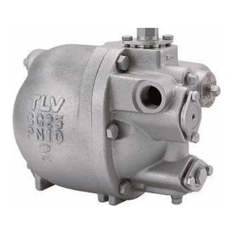
TLV
TLV PowerTrap GT5C User manual
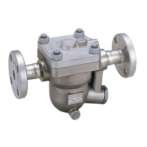
TLV
TLV JH5SL-P User manual
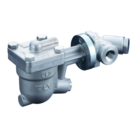
TLV
TLV QuickTrap FJ32-X User manual
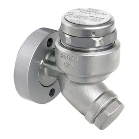
TLV
TLV PowerDyne QuickTrap P46UC-Y User manual

TLV
TLV QuickTrap FP32 User manual
TLV
TLV JH7.5R-P User manual
TLV
TLV DC3-L User manual
