TLV J3S-X-RV User manual
172-65584MA-04 (J3S-X-RV) 5 October 2021
Bypass Blowdown Steam Trap
(Free Float Steam Trap with X-element)
J3S-X-RV
Copyright © 2021 by TLV CO., LTD.
All rights reserved

172-65584MA-04 (J3S-X-RV) 5 Oct 2021
1
Contents
Introduction .......................................................................1
Safety Considerations.......................................................2
Checking the Piping..........................................................4
Operation ..........................................................................5
Specifications....................................................................6
Configuration.....................................................................6
Installation.........................................................................8
Maintenance......................................................................9
Operating Instructions for Regulation Valve....................10
Disassembly/Reassembly...............................................12
Instructions forPlug/HolderDisassemblyandReassembly...15
Troubleshooting ..............................................................16
TLV EXPRESS LIMITED WARRANTY...........................17
Service ............................................................................19
Options............................................................................20
Introduction
Thank you for purchasing the TLV bypass blowdown steam trap (free float steam trap
with X-element).
This product has been thoroughly inspected before being shipped from the factory.
When the product is delivered, before doing anything else, check the specifications
and external appearance to make sure nothing is out of the ordinary. Also be sure to
read this manual carefully before use and follow the instructions to be sure of using
the product properly.
This free float steam trap is of a revolutionary design that employs a high-
performance X-element as an air vent. It is best suited for steam equipment use. The
X-element is very sensitive to changes in temperature, and responds with great
accuracy, allowing for the quick discharge of large quantities of initial air and cold
condensate immediately after operation start-up, reducing start-up times. It also
reacts with great sensitivity to the inflow of large quantities of condensate and hot air
during operation, preventing air binding.
This steam trap, which combines the superior features of the X-element with the
proven performance record of the free float, increases heating efficiency and reduces
manpower requirements for maintenance and bypass blowdown.
The regulation valve incorporated into the cover makes bypass blow possible. In
addition to discharging condensate and air produced on startup through the orifice
and air vent valve, the regulation valve can be employed to increase condensate and
air discharge for more rapid start-up. Also by adjusting the aperture of the regulation
valve, it can be used to force steam discharge in order to solve problems with
condensate drainage on cylinder dryers or equipment prone to condensate backup
due to steam locking phenomenon.
If detailed instructions for special order specifications or options not contained in this
manual are required, please contact TLV for full details.
This instruction manual is intended for use with the model(s) listed on the front cover.
It is necessary not only for installation but for subsequent maintenance, disassembly/
reassembly and troubleshooting. Please keep it in a safe place for future reference.

172-65584MA-04 (J3S-X-RV) 5 Oct 2021
2
Safety Considerations
Read this section carefully before use and be sure to follow the instructions.
Installation, inspection, maintenance, repairs, disassembly, adjustment and valve
opening/closing should be carried out only by trained maintenance personnel.
The precautions listed in this manual are designed to ensure safety and prevent
equipment damage and personal injury. For situations that may occur as a result
of erroneous handling, three different types of cautionary items are used to
indicate the degree of urgency and the scale of potential damage and danger:
DANGER, WARNING and CAUTION.
The three types of cautionary items above are very important for safety: be sure to
observe all of them as they relate to installation, use, maintenance, and repair.
Furthermore, TLV accepts no responsibility for any accidents or damage occurring
as a result of failure to observe these precautions.
Symbols
Indicates a DANGER, WARNING or CAUTION item.
Indicates an urgent situation which poses a threat of death or
serious injury
Indicates that there is a potential threat of death or serious injury
Indicates that there is a possibility of injury or equipment / product
damage
NEVER apply direct heat to the float.
The float may explode due to increased internal pressure, causing
accidents leading to serious injury or damage to property and
equipment.
Install properly and DO NOT use this product outside the
recommended operating pressure, temperature and other
specification ranges.
Improper use may result in such hazards as damage to the product
or malfunctions that may lead to serious accidents. Local regulations
may restrict the use of this product to below the conditions quoted.
DO NOT use this product in excess of the maximum operating
pressure differential.
Such use could make discharge impossible (blocked).
Take measures to prevent people from coming into direct
contact with product outlets.
Failure to do so may result in burns or other injury from the
discharge of fluids.
Continued on the next page
DANGER
WARNING
CAUTION
WARNING
CAUTION
172-65584MA-04 (J3S-X-RV) 5 Oct 2021
3
Use gloves when operating the regulation valve and keep all
body parts well clear of the product.
Failure to do so could result in burns, other injury or damage from
the blowing of small amounts of steam and condensate.
When disassembling or removing the product, wait until the
internal pressure equals atmospheric pressure and the surface
of the product has cooled to room temperature.
Disassembling or removing the product when it is hot or under
pressure may lead to discharge of fluids, causing burns, other
injuries or damage.
Be sure to use only the recommended components when
repairing the product, and NEVER attempt to modify the
product in any way.
Failure to observe these precautions may result in damage to the
product and burns or other injury due to malfunction or the
discharge of fluids.
Use only under conditions in which no freeze-up will occur.
Freezing may damage the product, leading to fluid discharge, which
may cause burns or other injury.
Use only under conditions in which no water hammer will
occur.
The impact of water hammer may damage the product, leading to
fluid discharge, which may cause burns or other injury.
CAUTION

172-65584MA-04 (J3S-X-RV) 5 Oct 2021
4
Checking the Piping
Use only under conditions in which no water hammer will occur. The
impact of water hammer may damage the product, leading to fluid
discharge, which may cause burns or other injury.
CAUTION
Check to make sure that the pipes to be connected to the product have been
installed properly.
1. Is the pipe diameter suitable?
2. Is the piping where the product is to be installed horizontal?
3. Has sufficient space been secured for maintenance?
4. Have maintenance valves been installed at the inlet and outlet? If the outlet is
subject to back pressure, has a check valve (TLV-CK) been installed?
5. Is the inlet pipe as short as possible, with as few bends as possible, and installed
so the liquid will flow naturally down into the product?
6. Has the piping work been done correctly, as shown in the figures below?
Requirement
Correct
Incorrect
Install catchpot with the
proper diameter.
Diameter is too small.
Make sure the flow of
condensate is not
obstructed.
Diameter is too small and inlet
protrudes into pipe interior.
To prevent rust and scale
from flowing into the trap,
the inlet pipe should be
connected 25 to 50 mm (1
to 2 in) above the base of
the T-pipe.
Rust and scale flow into the
trap with the condensate.
When installing on the blind
end, make sure the flow of
condensate is not
obstructed.
Condensate collects in the
pipe.
172-65584MA-04 (J3S-X-RV) 5 Oct 2021
5
Operation
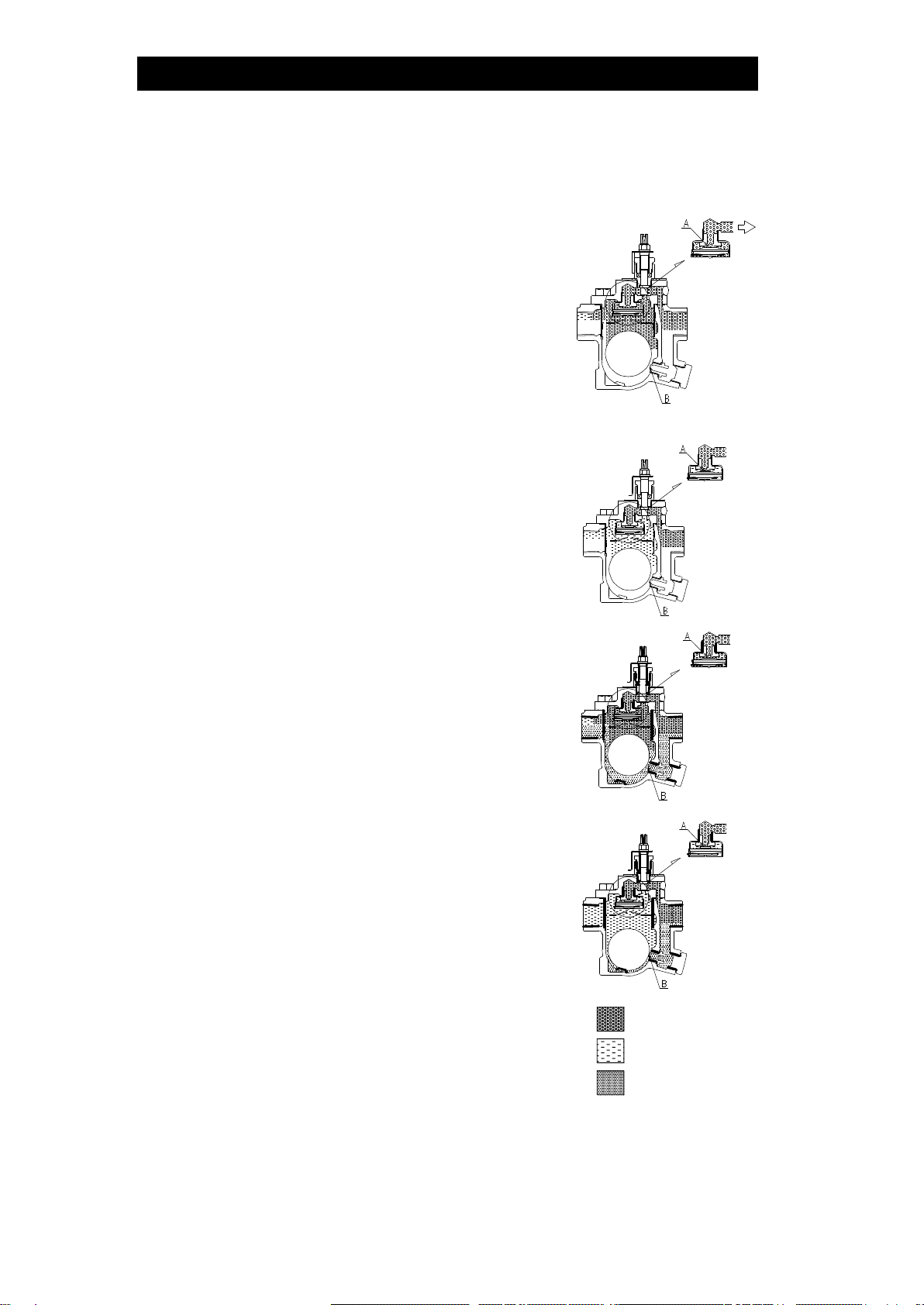
Principles of air and condensate discharge:
1. Initial Air and Cold Condensate Discharge
At startup, before steam is supplied, the trap is
cold so the X-element is contracted and the air
vent valve seat (A) is open. This allows for the
rapid discharge of air through the air vent valve
(A) and cold condensate through the orifice (B),
when steam is first supplied to the system.
Initial air/condensate can be discharged rapidly
using the regulation valve as necessary.
2. Condensate Discharge
After the discharge of initial air and cold
condensate (regulation valve closed), the heat of
the inflowing steam and condensate causes the
X-element to expand, closing the air vent valve
(A). The rising condensate level causes the float
to rise due to buoyancy, opening the orifice (B)
and allowing condensate to be discharged.
3. Hot Air Discharge
Should hot air flow into the trap with the steam
during normal operation, the temperature of the
X-element drops, causing it to momentarily
contract and open the air vent valve (A), which
allows for the rapid discharge of the air. After the
air is discharged and steam contacts the
X-element, the temperature will increase
causing the air vent valve (A) to close
4. Closed Position
When the condensate flow rate decreases, the
float falls as condensate is discharged, closing off
the orifice (B). A water seal is maintained at all
times over the orifice (B) to prevent steam loss.
NOTE: The high steam temperature causes the
X-element to expand, keeping the air
vent closed.
Air
Steam
Condensate
Regulation valve: open
Regulation valve: closed

172-65584MA-04 (J3S-X-RV) 5 Oct 2021
6
Specifications
Install properly and DO NOT use this product outside the recommended
operating pressure, temperature and other specification ranges.
Improper use may result in such hazards as damage to the product or
malfunctions which may lead to serious accidents. Local regulations
may restrict the use of this product to below the conditions quoted.
CAUTION
DO NOT use this product in excess of the maximum operating pressure
differential; such use could make discharge impossible (blocked).
CAUTION
Use only under conditions in which no freeze-up will occur. Freezing
may damage the product, leading to fluid discharge, which may cause
burns or other injury.
CAUTION
Refer to the product nameplate for detailed specifications.
* Maximum allowable pressure (PMA) and maximum allowable temperature (TMA) are PRESSURE
SHELL DESIGN CONDITIONS, NOT OPERATING CONDITIONS.
** Valve No. is displayed for products with options. This item is omitted from the nameplate when there
are no options.
Configuration
Model
Maximum Allowable
Temperature (TMA)*
Maximum Allowable
Pressure*
Nominal Diameter
Maximum Differential
Pressure
Production Lot No.
Valve No.**
Maximum Operating
Temperature

172-65584MA-04 (J3S-X-RV) 5 Oct 2021
7
No.
Name
M*
R*
F*
V*
1
Body
2
Cover
3
Float
4
Orifice Plug
5
Orifice Plug Gasket
6
Orifice
7
Orifice Gasket
8
Screen
9
Cover Gasket
10
Nameplate
11
Float Cover
12
X-element Guide
13
X-element
14
Spring Clip
15
Air Vent Valve Seat
16
Connector
17
Cover Bolt
18
Regulation Valve
19
Gland Case
20
Gland Retainer Nut
21
Gland Packing
22
Pin
23
Washer
24
Locknut
25
Gland Case Gasket
26
Aperture Indicator
27
Aperture Indication Plate
* Replacement parts are available only in
the following kits:
M = Maintenance Kit R = Repair Kit
F=Float V = Regulation Valve Unit

172-65584MA-04 (J3S-X-RV) 5 Oct 2021
8
Installation
Install properly and DO NOT use this product outside the recommended
operating pressure, temperature and other specification ranges.
Improper use may result in such hazards as damage to the product or
malfunctions which may lead to serious accidents. Local regulations
may restrict the use of this product to below the conditions quoted.
CAUTION
Take measures to prevent people from coming into direct contact with
product outlets. Failure to do so may result in burns or other injury from
the discharge of fluids.
CAUTION
Installation, inspection, maintenance, repairs, disassembly, adjustment and valve
opening/closing should be carried out only by trained maintenance personnel.
1. Before installation, be sure to remove all protective seals.
2. Before installing the product, open the inlet valve and blow out the piping to
remove any piping scraps, dirt and oil. Close the inlet valve after blowdown.
3. Install the product so the arrow on the body is pointing in the direction of flow.
4. The product should be inclined no more than 5° horizontally and front-to-back.
5. Install a condensate outlet valve and outlet piping.
6. Open the inlet and outlet valves and ensure that the product functions properly.
If there is a problem, determine the cause using the “Troubleshooting” section in this
manual.
Tolerance Angle for Installation: 5°
Make sure the product is installed with the raised TLV lettering on the body horizontal.

172-65584MA-04 (J3S-X-RV) 5 Oct 2021
9
Maintenance
Take measures to prevent people from coming into direct contact with
product outlets. Failure to do so may result in burns or other injury from
the discharge of fluids.
CAUTION
Be sure to use only the recommended components when repairing the
product, and NEVER attempt to modify the product in any way. Failure to
observe these precautions may result in damage to the product or burns
or other injury due to malfunction or the discharge of fluids.
CAUTION
Operational Check
Before carrying out a visual inspection, make sure that the regulation valve is closed.
A visual inspection of the following items should be done on a daily basis to
determine whether the product is operating properly or has failed. Periodically (at
least biannually) the operation should also be checked by using diagnostic
equipment, such as a stethoscope, thermometer, TLV Pocket TrapMan or TLV
TrapMan.
To confirm that the regulation valve is closed, make sure that the aperture indicator
for the regulation valve points to “0%”on the aperture indication plate. If the valve
cannot be fully closed, there is a problem. Refer to the “Troubleshooting”section to
locate and remedy the cause.
If the product or the regulation valve should fail, it may cause damage to piping and
equipment, resulting in faulty or low quality products or losses due to steam leakage.
Normal:
Condensate is discharged continuously, together with flash
steam, and the sound of flow can be heard. If there is very little
condensate, there is almost no sound of flow.
Blocked:
(Discharge Impossible)
No condensate is discharged. The product is quiet and makes no
noise, and the surface temperature of the product is low.
Blowing:
Live steam continually flows from the outlet and there is a
continuous metallic sound.
Steam Leakage:
Live steam is discharged through the product outlet together with
condensate, accompanied by a high-pitched sound.
(When conducting a visual inspection, flash steam is sometimes mistaken for steam leakage.
For this reason, the use of a steam trap diagnostic instrument –such as TLV TrapMan –in
conjunction with the visual inspection is highly recommended.)
Flash Steam
Live Steam Leakage
Parts Inspection
When parts have been removed, or during periodic inspections, use the following
table to inspect the parts and replace any that are found to be defective.
Procedure
Gaskets: Check for warping or scratches
Screen: Check for clogging or corrosion
X-element, Air Vent Valve Seat: Check for scratches
Float: Check for scratches or dents
Regulation Valve: Check for scratches on the surface
Body Interior: Check for build-up
Orifice Opening: Check for dirt, oil film, wear or scratches
White jet
containing
water droplets
Clear,
slightly
bluish jet
172-65584MA-04 (J3S-X-RV) 5 Oct 2021
10
Operating Instructions for Regulation Valve
Use gloves when operating the regulation valve and keep all body parts
well clear of the product. Failure to do so could result in burns, other injury
or damage from the blowing of small amounts of steam and condensate.
CAUTION
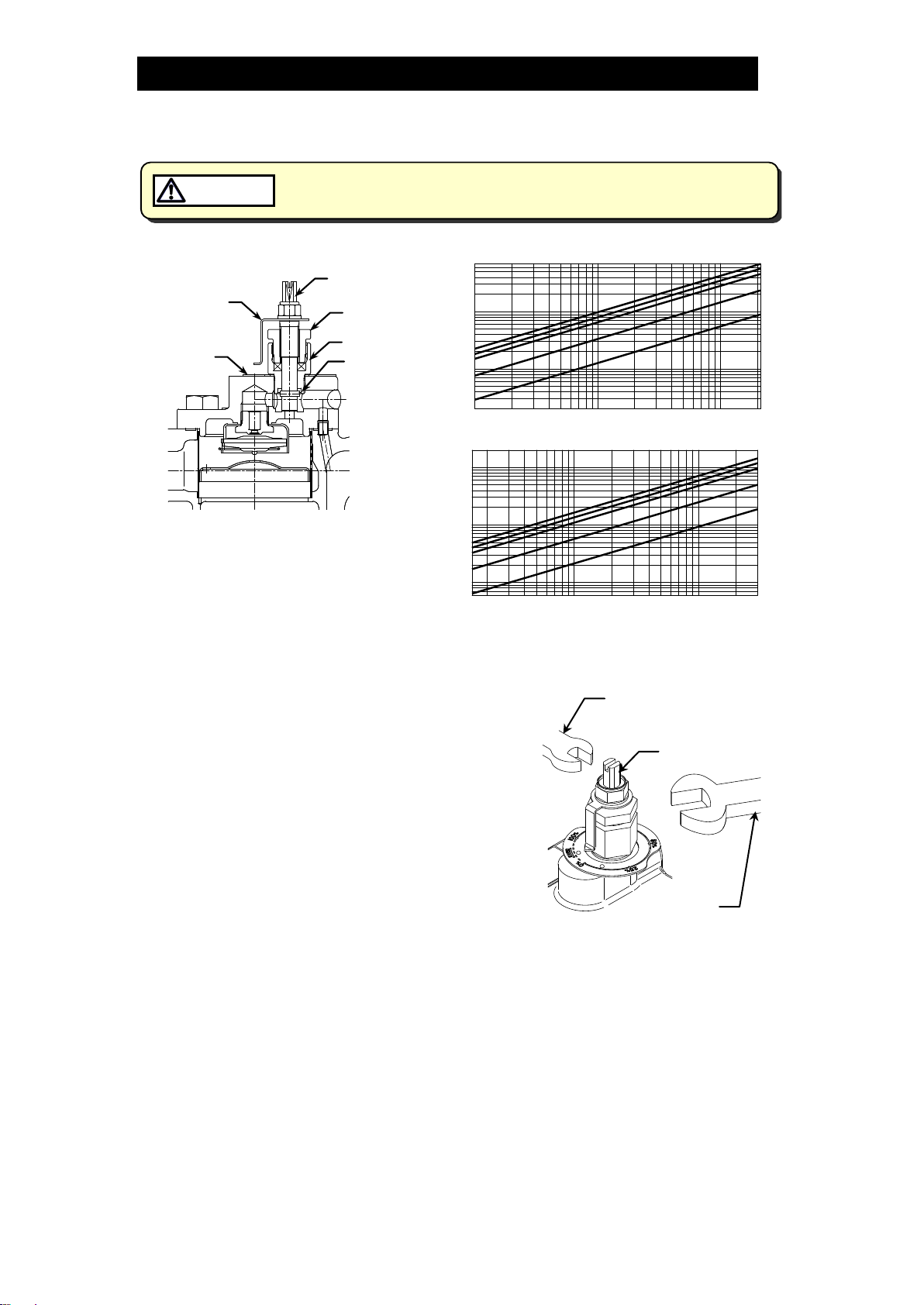
Regulation Valve Unit
Steam Discharge Capacity Graph
Operating Procedure
1. When the product is shipped from the factory,
the regulation valve is positioned in the lowest,
valve-closed position.
2. Tools required (the regulation valve can be
operated with any of the tools listed below):
・Spanner (7 mm (9/32 in) across flats),
adjustable wrench, flat-head screwdriver,
handle (optional)
3. The following operating instruction is for the
case that a spanner is used.
4. When operating the regulation valve, make
sure to hold the hexagonal part of the gland
case in place.
(Use a part of the hexagonal section that does
not touch the aperture indicator.)
・When using the regulation valve for the bypass blowdown function (to shorten
initial start-up time, etc.):
Use in a fully-opened position (aperture: 100%) at normal operation, then
back to fully-closed position (aperture: 0%) once blowdown is complete.
・When using the regulation valve to eliminate steam locking, etc.:
Reference the Steam Discharge Capacity graph and the percent open
marking on the aperture indication plate to adjust the amount of steam blow.
NOTE: When operating the regulation valve, make sure to use tools specified in
step 2. Use the same tool for opening/closing the valve, as much as
possible. If the valve is opened/closed with a spanner, adjustable wrench
or a handle, it may be difficult to operate it with a flat-head screwdriver
afterwards (as these tools are capable of tightening to a much higher
Regulation
Valve
Gland
Retainer Nut
GlandCase
Aperture
Indicator
Aperture
Indication
Plate Pin
1
5
10
50
70
0.01 0.03 0.05 0.1 0.3 0.5 1.0 2.0
Discharge Capacity (kg/h)
Differential Pressure (MPa)
0.5
0.2
100%
75%
50%
25%
10%
0.2
2
20
2.1
Aperture
5
10
50
100
1.5 3 5 10 30 50 100 200
Discharge Capacity (lb/h)
Differential Pressure (psi)
1
20
100%
75%
50%
25%
10%
0.6
2
20
730070
Aperture
200
Spanner,
Adjustable wrench,
Flat-head screw driver,
Handle (optional)
Square part
Spanner
(for holding the
gland case)

172-65584MA-04 (J3S-X-RV) 5 Oct 2021
11
degree). In that case, use a spanner, adjustable wrench or handle.
Do not turn the locknut, gland retainer nut, gland case, etc. while
adjusting the regulation valve. Failure to do so could result in burns, other
injury or damage from the blowing of small amounts of steam and
condensate.
For opening the valve:
・Fit a spanner onto the the square part of the top of the regulation valve and
turn slowly in the counterclockwise direction.
NOTE: Do not turn the regulation valve past the point at which it stops (where
the internal pin contacts the gland case)
・The steam quantity can be adjusted by using the Steam Discharge Capacity
Graph to find out what valve aperture corresponds to your desired steam
discharge quantity and differential pressure, then using the valve aperture
indication plate to set the valve aperture to the value taken from the graph.
For closing the valve:
・Fit a spanner onto the the square part of the very top of the regulation valve
and turn slowly in the clockwise direction.
5. If steam should leak from the gland retainer nut or gland case, it can be stopped
by further tightening the gland retainer nut. (Turn the regulation valve as far
closed as it will go.)
172-65584MA-04 (J3S-X-RV) 5 Oct 2021
12
Disassembly/Reassembly
NEVER apply direct heat to the float. The float may explode due to
increased internal pressure, causing accidents leading to serious injury
or damage to property and equipment.
WARNING
When disassembling or removing the product, wait until the internal
pressure equals atmospheric pressure and the surface of the product
has cooled to room temperature. Disassembling or removing the
product when it is hot or under pressure may lead to discharge of fluids,
causing burns, other injuries or damage.
CAUTION
Use the following procedures to remove components. Use the same procedures in
reverse to reassemble.
(Installation, inspection, maintenance, repairs, disassembly, adjustment and valve
opening/closing should be carried out only by trained maintenance personnel.)
Drain Plug (Option)
Part
During Disassembly
During Reassembly
Drain Plug
Remove with a socket
wrench
Consult the table of tightening torques and tighten
to the proper torque
Drain Plug
Gasket
Remove the gasket and
clean sealing surfaces
Replace with a new gasket; coat surfaces with anti-
seize
Detaching/Reattaching the Cover
Part
During Disassembly
During Reassembly
Cover Bolt
Remove with a socket
wrench
Consult the table of tightening torques and tighten
to the proper torque
Cover
Remove by lifting up and
off
Make sure there are no pieces of the old gasket
left on the sealing surfaces of the body and cover,
align the cover with the body and connector and
reattach
Connector
Remove the connector
Reinsert into the hole in the body
Cover Gasket
Remove the gasket and
clean sealing surfaces
Replace with a new gasket if misshapen or
damaged
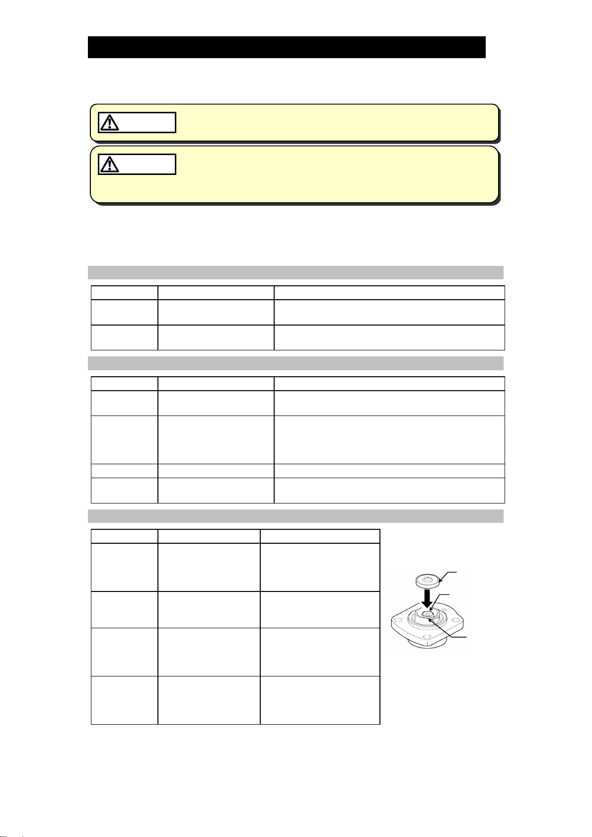
Disassembly/Reassembly of Components Inside the Cover
Part
During Disassembly
During Reassembly
Figure A
Spring Clip
Pinch the insides
together and remove
from the X-element
guide
Insert securely into the
groove in the guide
X-element
Remove from the
X-element guide
Insert after making sure it
is in the correct
orientation (Figure A)
Air Vent Valve
Seat
Remove with a
socket wrench
Consult the table of
tightening torques and
tighten to the proper
torque
X-element
Guide
Remove without
bending
Fix with the air vent valve
seat and make sure the
X-element can be
inserted smoothly
X-element
Air Vent
Valve Seat
X-element
Guide

172-65584MA-04 (J3S-X-RV) 5 Oct 2021
13
Detaching/Reattaching the Regulation Valve Unit
Part
During Disassembly
During Reassembly
Figure B
Regulation
Valve Unit*
Remove with a
spanner
(use spanner only on
Gland Case section)
See "NOTE when assembling
the unit" described below;
consult the table of tightening
torques and tighten to the
proper torque
Gland Case
Gasket
and clean sealing
surfaces
Replace with a new gasket;
coat surfaces with anti-seize
*The regulation valve unit cannot be disassembled It can only be
detached/reattached as a unit.
NOTE: When assembling the unit:
When installing the regulation valve unit in the cover,
make sure that the zero points of the aperture indicator
and the aperture indication plate are aligned. If the zero
points do not match up, they must be realigned.
Refer to the following steps for aligning the zero points:
1. Turn the regulation valve of the regulation valve unit counterclockwise and
pull it up.
2. Loosen the locknut of the regulation valve.
3. Install the gland case gasket and the regulation valve unit in the cover (refer
to the “Table of Tightening Torques”).
4. Turn the regulation valve clockwise to close using the appropriate tool.
5. Turn the aperture indicator portion of the regulation valve unit until its point
is aligned with the “0%” marking on the aperture indication plate. Once it is
aligned with the marking, tighten the locknut.
Disassembly/Reassembly of Components Inside the Body
Part
During Disassembly
During Reassembly
Figure C
Float Cover
& Screen
Lift straight up and out
while rocking slowly
Align the arrows on the float
cover/screen and the body,
insert with the tab on the
bottom fitting into the slot in the
body; make sure the screen
does not stick out out of the
body (Figure C)
Float
Remove, being careful
not to scratch the
surface
Insert, being careful not to
scratch the surface
Orifice Plug
Remove with a socket
wrench
Consult the table of tightening
torques and tighten to the
proper torque
Orifice Plug
Gasket
Remove the gasket
and clean sealing
surfaces
Replace with a new gasket;
coat surfaces with anti-seize
Orifice
Remove with a socket
wrench
Consult the table of tightening
torques and tighten to the
proper torque
Orifice Gasket
Remove the gasket
and clean sealing
surfaces
Replace with a new gasket;
coat surfaces with anti-seize
Regulation
Valve Unit
Locknut
Gland Case
Gasket
Arrow on the
Float Cover
Tab
172-65584MA-04 (J3S-X-RV) 5 Oct 2021
14
Table of Tightening Torques
Torque
Distance Across Flats
N∙m
(lbf·ft)
mm
(in)
Cover Bolt
50
(37)
17
(21/32)
Air Vent Valve Seat
35
(26)
19
(3/4)
Orifice Plug
80
(59)
24
(15/16)
Orifice
30
(22)
10
(3/8)
Gland Case
30
(22)
22
(7/8)
Gland Retainer Nut
30
(22)
22
(7/8)
(1 Nm 10 kgcm)
NOTE: - Coat all threaded portions with anti-seize.
- If drawings or other special documentation were supplied for the product,
any torque given there takes precedence over values shown here.
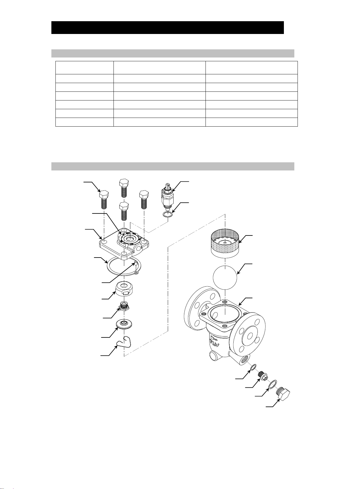
Exploded View
Screen
(Float Cover)
Float
Body
Orifice Gasket
Orifice
Orifice Plug Gasket
Orifice Plug
Cover Bolt
Cover
Cover Gasket
X-element
Guide
Air Vent
Valve Seat
X-element
Spring Clip
Connector
Gland Case Gasket
Regulation Valve Unit
Aperture
Indication
Plate
172-65584MA-04 (J3S-X-RV) 5 Oct 2021
15
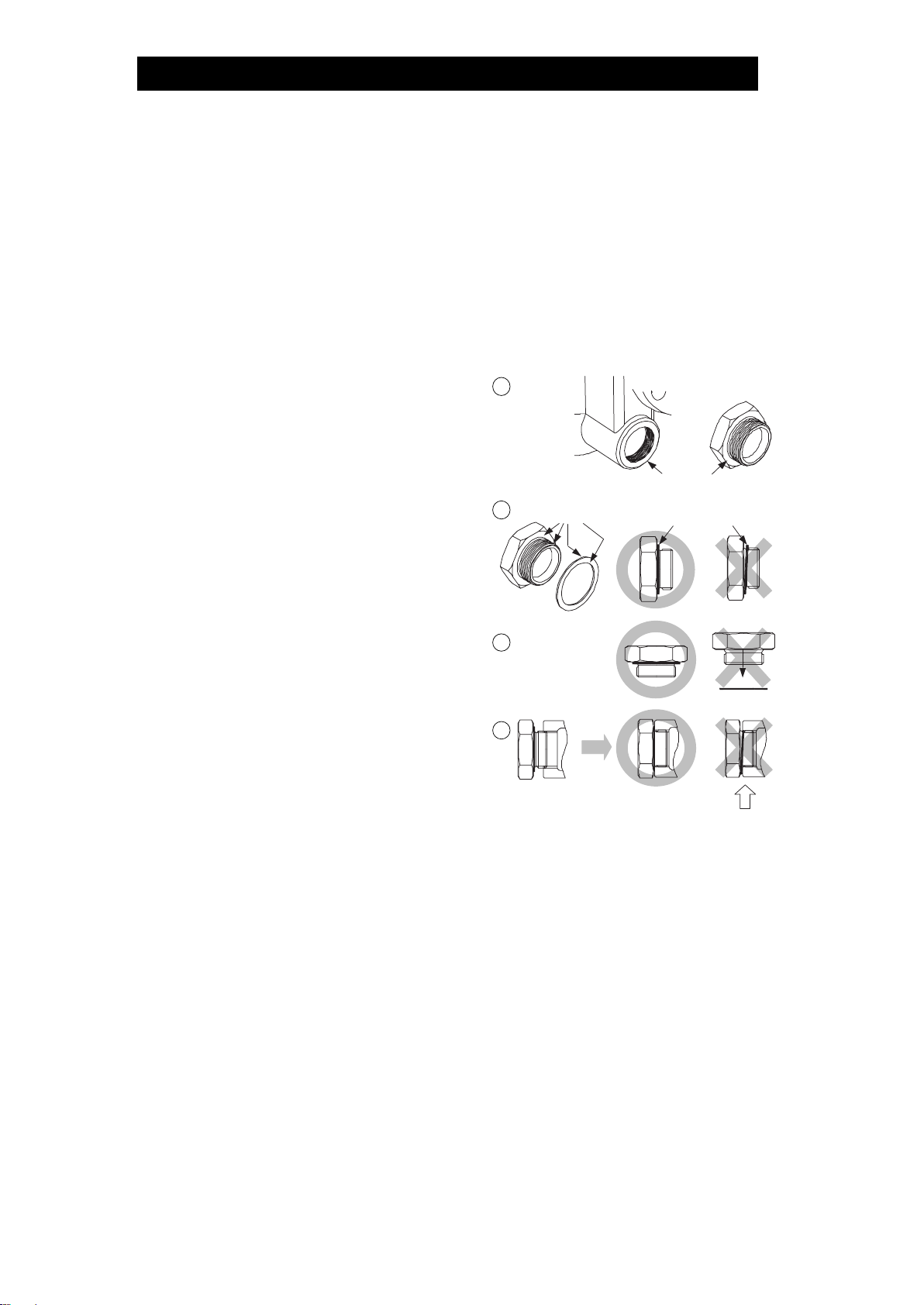
Instructions for Plug/Holder Disassembly and Reassembly
The seal on the threaded plugs/holders found on TLV products is formed by a flat
metal gasket. There are various installation orientations for the gaskets, such as
horizontal, diagonal and downward, and the gasket may be pinched in the thread
recesses during assembly.
Instructions for Disassembly and Reassembly
①Remove the plug/holder using a tool of the specified size (distance across flats).
②The gasket should not be reused. Be sure to replace it with a new gasket.
③Clean the gasket surfaces of the
plug/holder and the product body using a
rag and/or cleaning agents, then check to
make sure the surfaces are not scratched
or deformed.
④Coat both the gasket surface of the
plug/holder and the threads of the
plug/holder with anti-seize, then press the
gasket onto the center of the gasket
surface of the plug/holder, making sure
the anti-seize affixes the gasket tightly to
the plug/holder. Check to make sure the
gasket is not caught in the recesses of
the threads.
⑤Hold the plug/holder upside down to make
sure that the anti-seize makes the gasket
stick to the plug/holder even when the
plug/holder is held upside down.
⑥Screw the plug/holder by hand into the
product body while making sure that the
gasket remains tightly affixed to the
center of the gasket surface of the
plug/holder. Make sure the entire gasket
is making contact with the gasket surface
of the product body. It is important at this point to make sure the gasket is not
pinched in the thread recesses of the plug/holder.
⑦Tighten the plug/holder to the proper torque.
⑧Next, begin the supply of steam and check to make sure there is no leakage from
the part just tightened. If there is leakage, immediately close the inlet valve and,
if there is a bypass valve, take the necessary steps to release any residual
pressure. After the surface of the product cools to room temperature, repeat the
procedure beginning from step .
3
5
6
Gasket
Do not pinch gasket
in thread recesses
4Coat with anti-seize
Gasket Surface

172-65584MA-04 (J3S-X-RV) 5 Oct 2021
16
Troubleshooting
NEVER apply direct heat to the float. The float may explode due to
increased internal pressure, causing accidents leading to serious injury
or damage to property and equipment.
WARNING
When disassembling or removing the product, wait until the internal
pressure equals atmospheric pressure and the surface of the product
has cooled to room temperature. Disassembling or removing the
product when it is hot or under pressure may lead to discharge of fluids,
causing burns, other injuries or damage.
CAUTION
If the product fails to operate properly, use the following table to locate the cause and
remedy.
Problem
Cause
Remedy
No condensate is
discharged
(blocked) or
discharge is poor
The float is damaged or filled with
condensate
Replace with a new float
The orifice opening, screen or piping
are clogged with rust and scale
Clean parts
The X-element is scratched or damaged
Replace with a new X-element
The product operating pressure
exceeds the maximum specified
pressure, or there is insufficient
pressure differential between the
product inlet and outlet
Compare specifications and
actual operating conditions
Steam locking has occurred
Perform a bypass blowdown or
close the trap inlet valve and
allow the trap to cool
Steam is
discharged or leaks
from the outlet
(blowing)
(steam leakage)
Clogged orifice opening or regulation
valve opening, or rust and scale build-
up beneath the float
Clean parts
Scratches on the orifice
Replace with a new orifice
The float is misshapen or has surface
build-up
Clean or replace with a new float
Improper installation orientation
Correct the installation
Trap vibration
Lengthen the inlet piping and
fasten it securely
The regulation valve is opened
Close the regulation valve
The X-element and/or air vent valve
seat have surface build-up or are
scratched
Clean or replace with a new
X-element/ air vent valve seat
Steam is blowing
from the gland of
the regulation valve
The gland retainer nut is loose
Re-tighten the gland retainer
nut or replace with a new
regulation valve unit
The regulation valve
does not move
The regulation valve is clogged with
rust and scale
Clean parts or replace with a
new regulation valve unit
Steam is leaking
from a place other
than the outlet
Gasket deterioration or damage
Replace with new gasket(s)
Improper tightening torques were used
Tighten to the proper torque
Float frequently
becomes damaged
Water hammer has occurred
Study and correct the piping
NOTE: When replacing parts with new, use the parts list for reference, and replace with parts
from the Maintenance kit, Repair kit, etc. Please note that replacement parts are only
available as part of a replacement parts kit.

172-65584MA-04 (J3S-X-RV) 5 Oct 2021
17
TLV EXPRESS LIMITED WARRANTY
Subject to the limitations set forth below, TLV CO., LTD., a Japanese corporation
(“TLV”), warrants that products which are sold by it, TLV International Inc. (“TII”) or
one of its group companies excluding TLV Corporation (a corporation of the United
States of America), (hereinafter the “Products”) are designed and manufactured by
TLV, conform to the specifications published by TLV for the corresponding part
numbers (the “Specifications”) and are free from defective workmanship and
materials. The party from whom the Products were purchased shall be known
hereinafter as the “Seller”. With regard to products or components manufactured by
unrelated third parties (the “Components”), TLV provides no warranty other than the
warranty from the third party manufacturer(s), if any.
Exceptions to Warranty
This warranty does not cover defects or failures caused by:
1. improper shipping, installation, use, handling, etc., by persons other than TLV,
TII or TLV group company personnel, or service representatives authorized by
TLV; or
2. dirt, scale or rust, etc.; or
3. improper disassembly and reassembly, or inadequate inspection and
maintenance by persons other than TLV or TLV group company personnel, or
service representatives authorized by TLV; or
4. disasters or forces of nature or Acts of God; or
5. abuse, abnormal use, accidents or any other cause beyond the control of TLV,
TII or TLV group companies; or
6. improper storage, maintenance or repair; or
7. operation of the Products not in accordance with instructions issued with the
Products or with accepted industry practices; or
8. use for a purpose or in a manner for which the Products were not intended; or
9. use of the Products in a manner inconsistent with the Specifications; or
10. use of the Products with Hazardous Fluids (fluids other than steam, air, water,
nitrogen, carbon dioxide and inert gases (helium, neon, argon, krypton, xenon
and radon)); or
11. failure to follow the instructions contained in the TLV Instruction Manual for the
Product.
Duration of Warranty
This warranty is effective for a period of one (1) year after delivery of Products to the
first end user. Notwithstanding the foregoing, asserting a claim under this warranty
must be brought within three (3) years after the date of delivery to the initial buyer if
not sold initially to the first end user.
ANY IMPLIED WARRANTIES NOT NEGATED HEREBY WHICH MAY ARISE BY
OPERATION OF LAW, INCLUDING THE IMPLIED WARRANTIES OF MERCHANTABILITY
AND FITNESS FOR A PARTICULAR PURPOSE AND ANY EXPRESS WARRANTIES NOT
NEGATED HEREBY, ARE GIVEN SOLELY TO THE INITIAL BUYER AND ARE LIMITED IN
DURATION TO ONE (1) YEAR FROM THE DATE OF SHIPMENT BY THE SELLER.
Exclusive Remedy
THE EXCLUSIVE REMEDY UNDER THIS WARRANTY, UNDER ANY EXPRESS
WARRANTY OR UNDER ANY IMPLIED WARRANTIES NOT NEGATED HEREBY
(INCLUDING THE IMPLIED WARRANTIES OF MERCHANTABILITY AND FITNESS FOR A
PARTICULAR PURPOSE), IS REPLACEMENT; PROVIDED: (a) THE CLAIMED DEFECT IS

172-65584MA-04 (J3S-X-RV) 5 Oct 2021
18
REPORTED TO THE SELLER IN WRITING WITHIN THE WARRANTY PERIOD, INCLUDING
A DETAILED WRITTEN DESCRIPTION OF THE CLAIMED DEFECT AND HOW AND WHEN
THE CLAIMED DEFECTIVE PRODUCT WAS USED; AND (b) THE CLAIMED DEFECTIVE
PRODUCT AND A COPY OF THE PURCHASE INVOICE IS RETURNED TO THE SELLER,
FREIGHT AND TRANSPORTATION COSTS PREPAID, UNDER A RETURN MATERIAL
AUTHORIZATION AND TRACKING NUMBER ISSUED BY THE SELLER. ALL LABOR
COSTS, SHIPPING COSTS, AND TRANSPORTATION COSTS ASSOCIATED WITH THE
RETURN OR REPLACEMENT OF THE CLAIMED DEFECTIVE PRODUCT ARE SOLELY
THE RESPONSIBILITY OF BUYER OR THE FIRST END USER. THE SELLER RESERVES
THE RIGHT TO INSPECT ON THE FIRST END USER’S SITE ANY PRODUCTS CLAIMED
TO BE DEFECTIVE BEFORE ISSUING A RETURN MATERIAL AUTHORIZATION. SHOULD
SUCH INSPECTION REVEAL, IN THE SELLER’S REASONABLE DISCRETION, THAT THE
CLAIMED DEFECT IS NOT COVERED BY THIS WARRANTY, THE PARTY ASSERTING
THIS WARRANTY SHALL PAY THE SELLER FOR THE TIME AND EXPENSES RELATED
TO SUCH ON-SITE INSPECTION.
Exclusion of Consequential and Incidental Damages
IT IS SPECIFICALLY ACKNOWLEDGED THAT THIS WARRANTY, ANY OTHER EXPRESS
WARRANTY NOT NEGATED HEREBY, AND ANY IMPLIED WARRANTY NOT NEGATED
HEREBY, INCLUDING THE IMPLIED WARRANTIES OF MERCHANTABILITY AND FITNESS
FOR A PARTICULAR PURPOSE, DO NOT COVER, AND NEITHER TLV, TII NOR ITS TLV
GROUP COMPANIES WILL IN ANY EVENT BE LIABLE FOR, INCIDENTAL OR
CONSEQUENTIAL DAMAGES, INCLUDING, BUT NOT LIMITED TO LOST PROFITS, THE
COST OF DISASSEMBLY AND SHIPMENT OF THE DEFECTIVE PRODUCT, INJURY TO
OTHER PROPERTY, DAMAGE TO BUYER’S OR THE FIRST END USER’S PRODUCT,
DAMAGE TO BUYER’S OR THE FIRST END USER’S PROCESSES, LOSS OF USE, OR
OTHER COMMERCIAL LOSSES. WHERE, DUE TO OPERATION OF LAW,
CONSEQUENTIAL AND INCIDENTAL DAMAGES UNDER THIS WARRANTY, UNDER ANY
OTHER EXPRESS WARRANTY NOT NEGATED HEREBY OR UNDER ANY IMPLIED
WARRANTY NOT NEGATED HEREBY (INCLUDING THE IMPLIED WARRANTIES OF
MERCHANTABILITY AND FITNESS FOR A PARTICULAR PURPOSE) CANNOT BE
EXCLUDED, SUCH DAMAGES ARE EXPRESSLY LIMITED IN AMOUNT TO THE
PURCHASE PRICE OF THE DEFECTIVE PRODUCT. THIS EXCLUSION OF
CONSEQUENTIAL AND INCIDENTAL DAMAGES, AND THE PROVISION OF THIS
WARRANTY LIMITING REMEDIES HEREUNDER TO REPLACEMENT, ARE INDEPENDENT
PROVISIONS, AND ANY DETERMINATION THAT THE LIMITATION OF REMEDIES FAILS
OF ITS ESSENTIAL PURPOSE OR ANY OTHER DETERMINATION THAT EITHER OF THE
ABOVE REMEDIES IS UNENFORCEABLE, SHALL NOT BE CONSTRUED TO MAKE THE
OTHER PROVISIONS UNENFORCEABLE.
Exclusion of Other Warranties
THIS WARRANTY IS IN LIEU OF ALL OTHER WARRANTIES, EXPRESS OR IMPLIED,
AND ALL OTHER WARRANTIES, INCLUDING BUT NOT LIMITED TO THE IMPLIED
WARRANTIES OF MERCHANTABILITY AND FITNESS FOR A PARTICULAR PURPOSE,
ARE EXPRESSLY DISCLAIMED.
Severability
Any provision of this warranty which is invalid, prohibited or unenforceable in any
jurisdiction shall, as to such jurisdiction, be ineffective to the extent of such invalidity,
prohibition or unenforceability without invalidating the remaining provisions hereof,
and any such invalidity, prohibition or unenforceability in any such jurisdiction shall
not invalidate or render unenforceable such provision in any other jurisdiction.

172-65584MA-04 (J3S-X-RV) 5 Oct 2021
19
Service
For Service or Technical Assistance: Contact your TLV representative or your regional TLV office.
In Europe:
Daimler-Benz-Straße 16-18, 74915 Waibstadt, Germany
Tel:
Fax:
[49]-(0)7263-9150-0
[49]-(0)7263-9150-50
Units 7 & 8, Furlong Business Park, Bishops Cleeve, Gloucestershire GL52
8TW, U.K.
Tel:
Fax:
[44]-(0)1242-227223
[44]-(0)1242-223077
Parc d’Ariane 2, bât. C, 290 rue Ferdinand Perrier, 69800 Saint Priest,
France
Tel:
Fax:
33–(0)4-72482222
[33]-(0)4-72482220
In North America:
13901 South Lakes Drive, Charlotte, NC 28273-6790, U.S.A.
Tel:
Fax:
[1]-704-597-9070
[1]-704-583-1610
In Mexico and Latin America:
Av. Jesús del Monte 39-B-1001, Col. Hda. de las Palmas, Huixquilucan,
Edo. de México, 52763, Mexico
Tel:
Fax:
[52]-55-5359-7949
[52]-55-5359-7585
In Oceania:
Unit 8, 137-145 Rooks Road, Nunawading, Victoria 3131, Australia
Tel:
Fax:
[61]-(0)3-9873 5610
[61]-(0)3-9873 5010
In East Asia:
36 Kaki Bukit Place, #02-01/02, Singapore 416214
Tel:
Fax:
[65]-6747 4600
[65]-6742 0345
Room 5406, No. 103 Cao Bao Road, Shanghai, China 200233
Tel:
Fax:
[86]-(0)21-6482-8622
[86]-(0)21-6482-8623
No.16, Jalan MJ14, Taman Industri Meranti Jaya, 47120 Puchong,
Selangor, Malaysia
Tel:
Fax:
[60]-3-8065-2928
[60]-3-8065-2923
252/94 (K-L) 17th Floor, Muang Thai-Phatra Complex Tower B,
Rachadaphisek Road, Huaykwang, Bangkok 10310, Thailand
Tel:
Fax:
[66]-2-693-3799
[66]-2-693-3979
#302-1 Bundang Technopark B, 723 Pangyo-ro, Bundang, Seongnam,
Gyeonggi, 13511, Korea
Tel:
Fax:
[82]-(0)31-726-2105
[82]-(0)31-726-2195
In the Middle East:
Building 2W, No. M002, POBox 371684, Dubai Airport FreeZone,Dubai, UAE
Email:
In Other Countries:
881 Nagasuna, Noguchi, Kakogawa, Hyogo 675-8511, Japan
Tel:
Fax:
[81]-(0)79-427-1818
[81]-(0)79-425-1167
Manufacturer:
881 Nagasuna, Noguchi, Kakogawa, Hyogo 675-8511, Japan
Tel:
Fax:
[81]-(0)79-422-1122
[81]-(0)79-422-0112
Table of contents
Other TLV Industrial Equipment manuals


