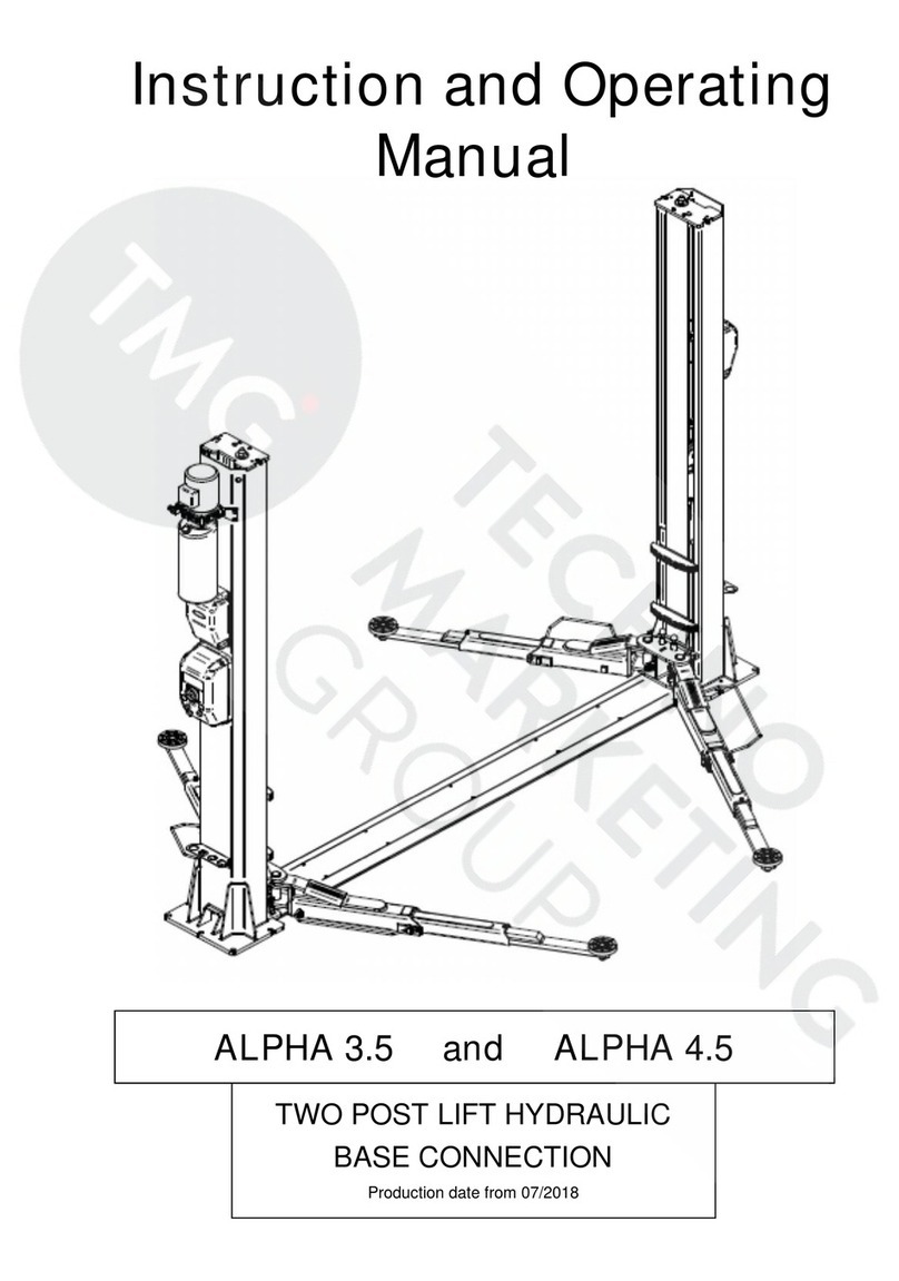
TMG TMG-ALT95 User manual

1,000lb MOTORCYCLE/ATV LIFT
MODEL:TMG-ALT95
9,500 LB TWO POST FLOOR PLATE
SYMMETRIC AUTO LIFT
Please read and understand the product manual completely before assembly
Check against the parts list to make sure all parts are received
Wear proper safety goggles or other protective gears while in assembly
Do not return the product to dealer. They are not equipped to handle your requests.
Missing parts or questions on assembly?
PRODUCT MANUAL
V2022.03.24
www.tmgindustrial.com Toll Free:1-877-761-2819

IMPORTANT NOTICE
Do not attempt to install this lift if you have never been trained on basic automotive lift installation procedures. Never
attempt to lift components without proper lifting tools such as forklift or cranes. Stay clear of any moving parts that
can fall and cause injury. These instructions must be followed to ensure proper installation and operation of your lift.
Failure to comply with these instructions can result in serious bodily harm and void product warranty. Manufacturer
will assume no liability for loss or damage of any kind, expressed or implied resulting from improper installation or use
of this product.
PLEASE READ ENTIRE MANUAL PRIOR TO INSTALLATION.
OWNER’S RESPONSIBILITY
To maintain the lift and user safety, the responsibility of the owner is to read and follow these instructions:
Follow all installation and operation instructions.
Make sure installation conforms to all applicable Local, State, and Federal Codes, Rules, and Regulations; such as
State and Federal OSHA Regulations and Electrical Codes.
Carefully check the lift for correct initial function.
Read and follow the safety instructions. Keep them readily available for machine operators.
Make certain all operators are properly trained, know how to safely and correctly operate the unit, and are properly
supervised.
Allow unit operation only with all parts in place and operating safely.
Carefully inspect the unit on a regular basis and perform all maintenance as required.
Service and maintain the unit only with authorized or approved replacement parts.
Keep all instructions permanently with the unit and all decals on the unit clean and visible.
BEFORE YOU BEGIN
Receiving:
The shipment should be thoroughly inspected as soon as it is received. The signed bill of lading is acknowledgement by the
carrier of receipt in good condition of shipment covered by your invoice. If any of the goods called for on this bill of lading are
shorted or damaged, do not accept them until the carrier makes a notation on the freight bill of the shorted or damaged
goods. Do this for your own protection.
NOTIFY THE CARRIER AT ONCE if any hidden loss or damage is discovered after receipt and request the carrier to
make an inspection. If the carrier will not do so, prepare a signed statement to the effect that you have notified the
carrier (on a specific date) and that the carrier has failed to comply with your request.
www.tmgindustrial.com 02/47 Toll Free:1-877-761-2819

Contents
TABLE OF CONTENTS
Page No.
Before You Begin . . . . . . . . . . . . . . . . . . . . .
. . . . . . . . . . . . . . . . . . . . . . . . . . . . . . .
. . . . . . . . . . . . . . . . . . . . . . . . . . . . . . . .
2
Installer/Operator Agreement/ Protective Equipment . . . . . . . . . . . . . . . . . . . . . .
. . . . . . . . . . . . . . . . . . . . . . . . . . . . . . . .
4
Introduction . . . . . . . . . . . . . . . . . . . . . . . . . .
. . . . . . . . . . . . . . . . . . . . . . . . . . . . . . .
. . . . . . . . . . . . . . . . . . . . . . . . . . . . . . . .
5
Safety / Warning Instructions . . . . . . . . . . .
. . . . . . . . . . . . . . . . . . . . . . . . . . . . . . .
. . . . . . . . . . . . . . . . . . . . . . . . . . . . . . . .
5
Tools Required . . . . . . . . . . . . . . . . . . . . . . .
. . . . . . . . . . . . . . . . . . . . . . . . . . . . . . .
. . . . . . . . . . . . . . . . . . . . . . . . . . . . . . . .
6
Step 1 / Selecting Site . . . . . . . . . . . . . . . . .
. . . . . . . . . . . . . . . . . . . . . . . . . . . . . . .
. . . . . . . . . . . . . . . . . . . . . . . . . . . . . . .
6
Step 2 / Floor Requirements . . . . . . . . . . . .
. . . . . . . . . . . . . . . . . . . . . . . . . . . . . .
. . . . . . . . . . . . . . . . . . . . . . . . . . . . . . . .
7
Concrete Specifications . . . . . . . . . . . . . . . .
. . . . . . . . . . . . . . . . . . . . . . . . . . . . . .
. . . . . . . . . . . . . . . . . . . . . . . . . . . . . . . .
8
Assembly View / Description of Parts
. .
. . . . . . . . . . . . . . . . . . . . . . . . . . . . . .
. . . . . . . . . . . . . . . . . . . . . . . . . . . . . . . .
8
Floor Plan . . . . . . . . . . . . . . . . . . . . . . . . . . . .
. . . . . . . . . . . . . . . . . . . . . . . . . . . . . .
. . . . . . . . . . . . . . . . . . . . . . . . . . . . . .
9
Clearances . . . . . . . . . . . . . . . . . . . . . . . . . . .
. . . . . . . . . . . . . . . . . . . . . . . . . . . . . .
. . . . . . . . . . . . . . . . . . . . . . . . . . . . . . . .
10
Step 3 / Post Preparation . . . . . . . . . . . . . .
. . . . . . . . . . . . . . . . . . . . . . . . . . . . . .
. . . . . . . . . . . . . . . . . . . . . . . . . . . . . .
10
Step 4 / Site Layout . . . . . . . . . . . . . . . . . . .
. . . . . . . . . . . . . . . . . . . . . . . . . . . . . .
. . . . . . . . . . . . . . . . . . . . . . . . . . . . . .
12
Step 5 / Installing Power Side Post . . . . . .
. . . . . . . . . . . . . . . . . . . . . . . . . . . . . .
. . . . . . . . . . . . . . . . . . . . . . . . . . . . . . . .
12
Step 6 / Installing Off Side Post . . . . . . . . .
. . . . . . . . . . . . . . . . . . . . . . . . . . . . . .
. . . . . . . . . . . . . . . . . . . . . . . . . . . . . . .
13
Step 7 / Mounting The Hydraulic Power Unit . . . . . . . . . . . . . . . . . . . . . . . . . . . . .
. . . . . . . . . . . . . . . . . . . . . . . . . . . . . . . .
13
Step 8 / Installing Hydraulic Lines . . . . . . . . . . . . . . . . . . . . . . . . . . . . . . . . . . . . . .
. . . . . . . . . . . . . . . . . . . . . . . . . . . . . . .
14
Step 9 /
Routing the Equalizer Cables
. . . . .
. . . . . . . . . . . . . . . . . . . . . . . . . . . . . . .
. . . . . . . . . . . . . . . . . . . . . . . . . . . . . . .
15
Step 10 / Installing Floor Plate and Safety Cover . . . . . . . . . . . . . . . . . . . . . . . . . . . . . . . . . . . . . . . . . . . . . . . . . . . . . . . . . . . 18
Step 11/Installing the Lift Arms . . . . . . . . .
. . . . . . . . . . . . . . . . . . . . . . . . . . . . . . .
. . . . . . . . . . . . . . . . . . . . . . . . . . . . . . .
18
Carriage Stop Bolt Installation Warning. . .
. . . . . . . . . . . . . . . . . . . . . . . . . . . . . . .
. . . . . . . . . . . . . . . . . . . . . . . . . .. . . . . .
22
Step 12 / Power Unit Connection . . . . . . . .
. . . . . . . . . . . . . . . . . . . . . . . . . . . . . .
. . . . . . . . . . . . . . . . . . . . . . . . . . . . . . .
24
Step 13 / Lift Start Up/ Final
Adjustments
. . . . . . . . . . . . . . . . . . . . . . . . .
. . . . . . . . . . . . . . . . . . . . . . . . . . . . . . .
. . . . . . . . . . . . . . . . . . . .. . . . . . . . . . . .
24
Post Installation Checklist
. . . . . . . . . . . . .
. . . . . . . . . . . . . . . . . . . . . . . . . . . . . .
. . . . . . . . . . . . . . . . . . . . . . . . . . . . . . .
25
Step 14 / Lubrication.
. . . . . . . . . . . . . . . . .
. . . . . . . . . . . . . . . . . . . . . . . . . . . . . .
. . . . . . . . . . . . . . . . . . . . . . . . . . . . . . .
25
Step 15 / Bleeding the Cylinders
. . . . . . . .
.................................
. . . . . . . . . . . . . . . . . . . . . . . . . . . . . . . . . .
26
Step16 /Optional Equipment Installation. . . . . . . . . . . . . . . . . . . . . . . . . . . . . . . . . . . . . . . . . . . . . . . . . . . . . . . . . . . . . . . . . 26
Operation/ Maintenance . . . . . . . . . . . . . .
. . . . . . . . . . . . . . . . . . . . . . . . . . . . . . .
. . . . . . . . . . . . . . . . . . . . . . . . . . . . . . .
26
Troubleshooting Guide
. . . . . . . . . . . . . . . .
. . . . . . . . . . . . . . . . . . . . . . . . . . . . . . .
. . . . . . . . . . . . . . . . . . . . . . . . . . . . . . .
39
Part Number Lists . . . . . . . . . . . . . . . . . . . . .
. . . . . . . . . . . . . . . . . . . . . . . . . . . . . . . . . . . . . . . . . . . . . . . . . . . . . . . . . . . . . .
43
www.tmgindustrial.com 03/47 Toll Free:1-877-761-2819

INSTALLER / OPERATOR
PLEASE READ AND FULLY UNDERSTAND. BY PROCEEDING YOU AGREE TO THE FOLLOWING:
I have visually inspected the site where the lift is to be installed and verified the concrete to be in good
condi-tion and free of cracks or other defects. I understand that installing a lift on cracked or defective
concrete could cause lift failure resulting in personal injury or death.
I understand that a level floor is required for proper installation and level lifting.
I understand that I am responsible if my floor is of questionable slope and that I will be responsible for
all charges related to pouring a new level concrete slab if required and any charges.
I will assume full responsibility for the concrete floor and condition thereof, now or later, where the
above equipment model is to be installed. Failure to follow Danger, Warning, and Caution instructions
may lead to serious personal injury or death to operator or bystander or damage to property.
I understand that lifts are designed to be installed in indoor locations only. Failure to follow installation
instructions may lead to serious personal injury or death to operator or bystander or damage to
property or lift.
Failure to follow Danger, Warning, and Caution instructions
may lead to serious personal injury or death to operator or
bystander or damage to property.
Please read the entire manual prior to installation. Do not operate this machine until you have read and have
understood all of the Danger, Warning and Caution alerts in this manual.
INSTALLER / OPERATOR PROTECTIVE EQUIPMENT
Personal protective equipment helps makes installation and operation safer, however, it does not take the place of
safe operating practices. Always wear durable work clothing during any installation and/or service activity. Shop
aprons or shop coats may also be worn, however loose-fitting clothing should be avoided. Tight-fitting leather gloves
are recommended to protect the technician’s hands when handling parts. Sturdy leather steel-toe work shoes and oil
resistant soles should be used by all service personnel to help prevent injury during typical installation and operation
activities.
Eye protection is essential during installation and operation activities. Safety glasses with
side shields, goggles, or face shields are acceptable. Back belts provide support during
lifting activities and are also helpful in providing worker protection.Consideration should
also be given to the use of hearing protection if service activity is performed in an enclosed
area, or if noise levels are high.
THIS SYMBOL POINTS OUT IMPORTANT SAFETY INSTRUCTIONS WHICH IF NOT FOLLOWED COULD ENDANGER
THE PERSONAL SAFETY AND/OR PROPERTY OR YOURSELF AND OTHERS AND CAN CAUSE PERSONAL INJURY
OR DEATH. READ AND FOLLOW ALL INSTRUCTIONS IN THIS MANUAL BEFORE ATTEMPTING TO OPERATE THIS
MACHINE.
www.tmgindustrial.com 04/47 Toll Free:1-877-761-2819

INTRODUCTION
1. Carefully remove the crating and packing materials. CAUTION! Be careful when cutting steel banding material
as items may become loose and fall causing personal harm or injury.
2. Check the voltage, phase, and proper amperage requirements for the motor shown on the motor plate.
Electrical work should be performed only by a certified electrician.
IMPORTANT SAFETY INSTRUCTIONS
Read these safety instructions entirely. Do not attempt to install this lift if you have never been trained on basic
automotive lift installation procedures. Never attempt to lift components without proper lifting tools such as forklift
or cranes. Stay clear of any moving parts that may fall and cause injury. When using your garage equipment, basic
safety precautions should always be followed, including the following:
1. Read and understand all instructions and all safety warnings before operating lift.
2. Care must be taken as burns can occur from touching hot parts.
3. Do not operate equipment with a damaged cord or if the equipment has been dropped or damaged until it has
been examined by a qualified service person.
4. Do not let a cord hang over the edge of the table, bench, or counter or come in contact with hot manifolds or
moving fan blades.
5. If an extension cord is necessary, a cord with a current rating equal to or more than that of the equipment should
be used. Cords rated for less current than the equipment may overheat. Care should be taken to arrange the
cord so that it will not be tripped over or pulled.
6. Always unplug equipment from electrical outlet when not in use. Never use the cord to pull the plug from the
outlet. Grasp plug and pull to disconnect.
7. Let equipment cool completely before putting away. Loop cord loosely around equipment when storing.
8. To reduce the risk of fire, do not operate equipment in the vicinity of open containers of flammable liquids
(gasoline).
9. Adequate ventilation should be provided when working on operating internal combustion engines.
10. Keep hair, loose clothing, fingers, and all parts of body away from moving parts. Keep feet clear of lift when
lowering. Avoid pinch points.
11. DANGER! To reduce the risk of electric shock, do not use on wet surfaces or expose to rain. The
power unit used on this lift contains high volt-age. Disconnect power at the receptacle or at the
circuit breaker switch before performing any electrical repairs. Secure plug so that it cannot be
accidentally plugged in during service. or mark circuit breaker switch so that it cannot be
accidentally switched on during service.
12. Use only as described in this manual.Use only manufacturer’s recommended attachments.
13. ALWAYS WEAR SAFETY GLASSES. Everyday eyeglasses only have impact resistant lenses,
they are not safety glasses.
14. Consider work environment. Keep work area clean. Cluttered work areas invite injuries. Keep
areas well lit.
15. Guard against electric shock. This lift must be grounded while in use to protect operator from
electric shock. Never connect the green power cord wire to a live terminal. This is for ground only.
16. Only trained operators should operate this lift. All non-trained personnel should be kept away from the work area.
Never let non-trained personnel come in contact with, or operate lift.
17. DO NOT override self-closing lift controls.
18. Clear area if vehicle is in danger of falling.
19. ALWAYS make sure the safeties are engaged before attempting to work on or near a vehicle.
www.tmgindustrial.com 05/47 Toll Free:1-877-761-2819

20. WARNING! RISK OF EXPLOSION. This equipment has internal arcing or sparking parts which should not be
exposed to flammable vapors. This machine should not be located in a recessed area or below floor level.
21. MAINTAIN WITH CARE. Keep lift clean for better and safer performance. Follow manual for proper lubrication
and maintenance instructions. Keep control handles and/or buttons dry, clean and free from grease and oil.
22. Check for damaged parts. Check for alignment of moving parts, breakage of parts or any condition that may
affect operation of lift. Do not use lift if any component is broken or damaged.
23. NEVER remove safety related components from the lift. Do not use lift if safety related components are missing
or damaged.
24. STAY ALERT. Use common sense and watch what you are doing. Remember, SAFETY FIRST.
TOOLS REQUIRED
Rotary-Hammer Drill or Similar
Large Crescent Wrench
3/4” Masonry Bit
Large Pipe Wrench
Hammer
Crow Bar
4 Foot Level
Chalk Line
Open-End Wrench Set: SAE/Metric
Medium Flat Screwdriver
Socket-And Ratchet Set: SAE/Metric
Tape Measure: 25 Foot Minimum
Hex-Key / Allen Wrench Set
Needle Nose Pliers
IMPORTANT NOTICE
These instructions must be followed to ensure proper installation and operation of your lift.
Failure to comply with these instructions can result in serious bodily harm and void product
warranty. Manufacturer will assume no liability for loss or damage of any kind, expressed or
implied resulting from improper installation or use of this product.
PLEASE READ ENTIRE MANUAL PRIOR TO INSTALLATION
STEP 1 (Selecting Site)
1. Before installing your new lift, check the following.
2. LIFT LOCATION: Always use architects plans when available. Check layout dimension against floor plan
requirements making sure that adequate space if avail-able.
3. OVERHEAD OBSTRUCTIONS: The area where the lift will be located should be free of overhead obstructions such
as heaters, building supports, electrical lines etc.
4. DEFECTIVE FLOOR: Visually inspect the site where the lift is to be installed and check for cracked or defective
concrete.
5. OPERATING TEMPERATURE. Operate lift only between temperatures of 41° -104° F.
6. Lift is designed for INDOOR INSTALLATION ONLY.
7. Outdoor use permitted only if covered and dry. Always follow warnings illustrated on equipment labels.
SAVE THESE INSTRUCTIONS
www.tmgindustrial.com 06/47 Toll Free:1-877-761-2819

STEP 2 (Floor Requirements)
This lift must be installed on a solid level concrete floor with no more than 3-degrees of slope. Failure to do so could
cause personal injury or death.
A level floor is suggested for proper use and installation and level lifting. If a floor is of questionable slope, consider a
survey of the site and/or the possibility of pouring a new level concrete slab.
DO NOT install or use this lift on any asphalt surface or any surface other than concrete.
DO NOT install or use this lift on expansion seams or on cracked or defective concrete.
DO NOT install or use this lift on a second / elevated floor without first consulting building architect.
CONCRETE SPECIFICATIONS
LIFT MODEL CONCRETE REQUIREMENTS
TMG-ALT95 4” Min. Thickness / 3,000 PSI
All models MUST be installed on 3000 PSI concrete only conforming to the minimum requirements shown above.
New concrete must be adequately cured by at least 28 days minimum.
When removing the lift from shipping angles, pay close attention as the posts can slide and can cause injury. Prior to
removing the bolts make sure the posts are held securely by a fork lift or some other heavy lifting device.
IMPORTANT NOTE:
Lifts are supplied with installation instructions and concrete fasteners meeting the criteria as prescribed by
the American National Standard "Automotive Lifts - Safety Requirements for Construction, Testing, and
Validation" ANSI/ALI ALCTV-2011. Lift buyers are responsible for any special regional structural and/or
seismic anchoring requirements specified by any other agencies and/or codes such as the Uniform Building
Code (UBC) and/or International Building Code (IBC).
www.tmgindustrial.com 07/47 Toll Free:1-877-761-2819

PARTS INVENTORY
Be sure to take a complete inventory of parts prior to beginning installation.
Description
Qty
Floor plate
1
Front Arm Assembly
2
Rear Arm Assembly
2
Off Side Post with Carriage Assembly
1
Power Side Post with Carriage Assembly
1
Hydraulic Cylinder
2
Hydraulic Power Unit
1
Power Side
Post Assembly
Floor Plate
Off Side Post
Assembly
Front And Rear Arm
Assemblies
Frame Contact Pad
Hydraulic
Power Unit
Hydraulic Cylinder
www.tmgindustrial.com 08/47 Toll Free:1-877-761-2819

FLOOR PLAN
MODEL
TMG-ALT95
Lifting Capacity
9,500 lbs. / 4320 kg.
A- Height Overall:
111” / 2824mm.
B -Width Overall:
136" / 3436 mm.
D- Floor Pan Height:
1-/5" /30 mm
F -Reach (Front Arm Min.):
30-1/2" / 776 mm.
G -Reach (Front Arm Max.):
48" / 1230 mm.
H- Reach (Rear Arm Min.):
31-1/2" / 800 mm.
I- Reach (Rear Arm Max.):
49" / 1249 mm.
J- Min. Pad Height:
3.95" / 100mm
Pad Adjustment
1-1/4”,5
"
K- Rise:
72" / 1830 mm.
L -Max Lift Height (Pad Only):
74-5/8
"
/ 1896mm
M - Max Lift Height (5" Adapter):
81
"
/ 2057mm
Standard Motor(*)
220 VAC / 60 Hz. 1Ph.
Time of Full Rise:
50 Seconds
Max Load Per Arm:
2,375 Lbs. / 1080 Kg.
Emission sound pressure at Operator Position < 70 dB(A) The design, material and specifications are subject to change without notice.
www.tmgindustrial.com 09/47 Toll Free:1-877-761-2819

CLEARANCES
STEP 3 (Post Preparation)
COMPLETE THE FOLLOWING PRIOR TO RAISING THE COLUMNS
NOTE:
DETERMINE DESIRED LOCATION AND WIDTH LAYOUTBEFORE RAISING COLUMNS.
1. Prior to raising posts, slide each carriage upwards to
expose the cylinder port in the base of the hydraulic
cylinder and to aid in sheave removal and equalizer
cable routing.
14”(350mm)
Minimum to nearest bay
or obstruction
15”
380
24”(610mm)
Minimum to nearest wall
132”
(3453mm)
Minimum to nearest
obstruction
156”
(3963mm)
Minimum to nearest
obstruction
105.4”
2676
LIFT HEIGHT CLEARANCE NOTE : there must be 70" plus the height of
typical vehicle min distance from top of lift to nearest obstruction.
Cylinder port
Fig 3.1
Slide carriage
upwards
www.tmgindustrial.com 10/47 Toll Free:1-877-761-2819

2. Install a 1/4” NPT straight fitting into each cylinder
port using Teflon tape then remove the cable
sheaves located at the inside bottom of each post
by first removing the hex head bolts, and then by
removing the sheave pin.
NOTE: When installing fitting DO NOT use teflon tape
on JIC fitting end
3. Route threaded end of cable downwards through the
bottom of the carriage and wrap the cable around the
cable sheave and re-install sheave by reversing the
sheave removal procedure. (See Fig 3.3) Leave excess
cable tied together in a coil to carriage until further
steps are required.
NOTE: Portions of Carriage and Post cut away for clarity
SITE LAYOUT / FLOOR PLAN
Fig 3.2
Remove cable
sheaves
Remove cable
sheaves
Install fitting
135.3”
3436mm
Fig 3.3
Threaded end
of cable
routed down
through
carriage
towards
opposite post
www.tmgindustrial.com 11/47 Toll Free:1-877-761-2819

STEP 4 (Site Layout)
1. Determine which side of the lift will be the approach side.
2. Now decide where the power unit will be located. The POWER SIDE column has the power unit mounting bracket
attached to the side.
3. Once a location is determined, use a carpenters chalk line to layout a grid for the post locations. Keep all
dimensions square within 1/8” (3mm) or malfunctioning of the lift can occur.
4. After the post locations are properly marked, use chalk or crayon to make an outline of the posts on the floor at
each post location using the post base plates as a template.(See Fig 4.1)
5. CHECK ALL DIMENSIONS TWICE and make sure that the layout is perfectly square.
STEP 5 (Installing the POWER SIDE post)
1. Before proceeding, double the check measurements and
make certain that the base plate of each post is aligned
with the chalk line.
2. Using the base plate on the POWER SIDE post as a guide,
drill each anchor hole in the concrete approximately 4” deep
using a rotary hammer drill and 3/4” concrete drill-bit. To
ensure full holding power, do not ream the hole or allow
the drill to wobble. (See Fig. 5.1)
3. After drilling, remove dust thoroughly from each hole
making certain that the posts remain aligned with the
chalk line.
4. Assemble the washers and nuts on the anchors then
tap into each hole with a hammer until the washer
rests against the base plate. If shimming is required be
sure that enough threads are left exposed. (See Fig. 5.2)
CHALK LINE
Fig 5.1
Fig 5.2
www.tmgindustrial.com 12/47 Toll Free:1-877-761-2819

5. If shimming is required, insert the shims as necessary
under the base plate so that when the anchor bolts are
tightened, the posts will be plumb. (See Fig. 5.3)
6. With the foot guards, shims and anchor bolts in place,
tighten by securing the nut to the base then turning 3-5
full turns clockwise. DO NOT use an impact wrench for
this procedure. (See Fig. 5.4)
STEP 6 (Installing the OFF SIDE post)
Position the OFF SIDE post at the designated chalk locations and secure post to floor following the same procedures
as outlined in STEP 5; Paragraphs 1-6.
STEP 7 (Mounting the Hydraulic Power Unit)
1. Attach the power unit to the POWER SIDE post. using
four M8 hex head bolts and nuts supplied.(See Fig 7.1)
2. Fill the reservoir with 10 WT. HYDRAULIC OIL OR
DEXRON ATF, approximately three gallons.Make sure
the funnel used to fill the Power Unit is clean.
Do not connect power unit hydraulic hose assembly at this
time.
Fig 5.4
NOTE: Not include the shimming
Fig 5.3
Fig 7.1
M8 x1.25 x 16mm hex
head bolts, M8 flat
washers and M8 nuts
(Qty 4 ea)
www.tmgindustrial.com 13/47 Toll Free:1-877-761-2819

DO NOT PERFORM ANY MAINTENANCE OR INSTALLATION OF ANY COMPONENTS WITHOUT FIRST
ENSURING THAT ELECTRICAL POWER HAS BEEN DISCONNECTED AT THE SOURCE OR PANEL AND CANNOT
BE RE-ENERGIZED UNTIL ALL MAINTENANCE AND/OR INSTALLATION PROCEDURES ARE COMPLETED.
DO NOT RUN POWER UNIT WITHOUT OIL. DAMAGE TO POWER UNIT PUMP CAN OCCUR. THE POWER UNIT
MUST BE KEPT DRY. DAMAGE TO POWER UNIT CAUSED BY WATER OR OTHER LIQUIDS SUCH AS
DETERGENTS, ACID ETC., IS NOT COVERED UNDER WARRANTY.
OPERATE LIFT ONLY BETWEEN TEMPERATURES OF 41 °- 104° F. IMPROPER ELECTRICAL HOOK-UP CAN
AMAGE MOTOR AND WILL NOT BE COVERED UNDER WARRANTY. MOTOR CAN NOT RUN ON 50HZ WITHOUT A
PHYSICAL CHANGE IN THE MOTOR.
USE A SEPARATE CIRCUIT BREAKER FOR EACH POWER UNIT. PROTECT EACH CIRCUIT WITH TIME DELAY
FUSE OR CIRCUIT BREAKER.
FOR 208-230VOLT, SINGLE PHASE, USE A 25 AMP FUSE.
3. The standard power unit for your lift is 220 volt, 60HZ,
single phase. All wiring must be performed by a certified
electrician only. SEE WIRING INSTRUCTIONS AFFIXED
TO MOTOR FOR PROPER WIRING INSTRUCTIONS.
STEP 8 (Installing Hydraulic Lines)
1. Connect the cylinder hoses to the straight fittings on the
cylinders. DO NOT use teflon tape on the JIC fitting end.
(See Fig 8.1)
ALL WIRING MUST BE PERFORMED
BY A LICENSED ELECTRICIAN.
Straight
Fitting
Fig 8.1
Cylinder
Hose
www.tmgindustrial.com 14/47 Toll Free:1-877-761-2819

2. Route the power unit hose between the cylinder shaft
and the equalizer sheave bracket. (See Fig 8.2)
3. Remove the plastic plug from the power unit power
port. Install the 90° power unit fitting with O-ring using
Teflon tape. (Connect the power unit hose assembly
to the 90° hydraulic fitting on the power unit.
DO NOT use teflon tape on the JIC hose fittings.
(See Fig 8.3)
STEP 9 (Routing the Equalizer Cables)
1. Raise and lock each carriage approximately 28”above
the ground. (See Fig. 9.1)
NOTE:
POWER PORT LOCATION IN HYDRAULIC POWER
UNIT MAY VARY. CONFIRM THE LOCATION OF
THE POWER PORT ENCLOSED IN THE POWER
UNIT DOCUMENTATION.
WHEN ROUTING HYDRAULIC HOSES THROUGH THE POSTS, ROUTE HOSES THROUGH THE HOSE IS CLEAR OF
ANY MOVING PARTS. IT MAY BE NECESSARY TO TIE THE HOSES CLEAR BY USING NYLON TIE STRAPS OR WIRE.
FAILURE TO KEEP THE HYDRAULIC HOSES CLEAR MAY RESULTIN THE HYDRAULIC HOSES TO FAIL, WHICH MAY
RESULT IN DAMAGE OR PERSONAL HARM.
MAKE SURE THAT THE SAFETY LOCKS ON EACH
POST ARE FULLY ENGAGED BEFORE ATTEMPTING
TO ROUTE EQUALIZER CABLES AND/OR HOSES.
CARRIAGES MUST BE EQUAL HEIGHT FROM THE
FLOOR BEFORE PROCEEDING.
90° Power
Unit Fitting
Power Unit
Hose
Fig 8.3
Fig 9.1
Cylinder
Hose
Straight
Fitting
Fig 8.2
www.tmgindustrial.com 15/47 Toll Free:1-877-761-2819

NOTE:
THERE WILL BE INITIAL STRETCHING OF THE
CABLES AND/OR WITH INCREASED LOADS.
ADJUST THE CABLES AS OUTLINED ABOVE A
WEEK AFTER FIRST USE, THEN EVERY THREE TO
SIX MONTHS THEREAFTER DEPENDING ON USAGE
AND/OR TO COMPENSATE FOR STRETCH.
THE EQUALIZER CABLE SHEAVES WILL NEED TO
BE REMOVED TO EASE THE ROUTING OF THE
EQUALIZER CABLES. BE SURE TO REINSTALL ALL
PINS, COVERS AND CLIPS OR SERIOUS DAMAGE
OR INJURY MAY OCCUR.
2. With the carriages locked at 28” off the floor, route
the threaded end of the equalizer cable across to the
opposite side base plate sheave and up through the
carriage. (See Fig. 9.2)
3. Route the threaded end up and over the Top Plate
sheave and back down to the carriage and reinstall
sheave. (See Fig. 9.3)
4. Insert the threaded end of the cable through the hole
on top of the carriage. Place M16 nut on threaded
cable end. Tighten cable nuts until taut, checking that
both cables have equal tension.(See Fig 9.4)
Fig 9.3
From
base
plate
sheave
To
lift
head
carriage
NOTE: Post cut away for clarity
Fig 9.2
From opposite
base plate sheave
NOTE: Post and carriage cut away for clarity
Fig 9.4
Threaded cable
end comes down
From Top Plate
sheave and into
hole on top of
carriage plate.
Threaded
Cable End
Nut
NOTE: Post cut
away for clarity
www.tmgindustrial.com 16/47 Toll Free:1-877-761-2819

WHEN THE CABLE ADJUSTING NUTS BOTTOM OUT ON THE THREADED END OF THE CABLE CONNECTOR AND
THERE IS STILL SLACK IN THE CABLES, THE CABLES HAVE STRETCHED BEYOND THE SAFE USEFUL LENGTH
AND NEED TO BE REPLACED WITH FACTORY APPROVEDCABLE ASSEMBLIES. DO NOT PLACE WASHERS,
SPACERS OR OTHER DEVICES TO “SHORTEN” THE EFFECTIVE CABLE LENGTH AS DAMAGE TO THE LIFT OR
INJURY TO PERSONS MAY OCCUR.
Cable Routing
www.tmgindustrial.com 17/47 Toll Free:1-877-761-2819

STEP 10 (Installing Floor Plate and Safety Cover)
1. After safeties have been adjusted and checked for proper
operation, install and tighten Power Side safety cover and
Off Side safety cover mounting screws. (See Fig. 10.1)
2. Install the floor plate between the columns as shown.
(See Fig. 10.2)
STEP 11 (Installing the Lift Arms)
1. Place the appropriate lift arm assembly in the lift heads.
2. Install the lift head pins into the lift head and through the holes in the arm assembly. (See Fig. 11.1 -11.2)
Lift Head
Pin
Lift Head
Pin
Lift Head
Fig. 11.1
Lift Head
Pin
Fig. 11.2
Lift Head
Pin
Fig 10.2
Screw
Fig 10.1
www.tmgindustrial.com 18/47 Toll Free:1-877-761-2819

NOTE:
LEFT AND RIGHT ARE DETERMINED WHEN FACING
THE INSIDE. OPEN SIDE OF THE LIFT POST.
THE ARM RESTRAINT GEARS MUST BE
POSITIONED AND ADJUSTED PROPERLY.
CONFIRMATION OF PROPER GEAR ENGAGEMENT
MUST BE MADE PRIOR TO THE OPERATION OF
THE LIFT. PERIODIC INSPECTION AND
ADJUSTMENT IS REQUIRED. FAILURE TO INSPECT
AND ADJUST THE ARM RESTRAINT GEARS ON ALL
FOUR ARMS PROPERLY CAN RESULT IN DAMAGE
TO THE VEHICLE OR INJURY AND/OR DEATH.
3. Each arm restraint gear can be oriented in a Left or Right configuration on the arms. Each arm and arm restraint gear
must be positioned in the proper location in the lift head. (See Fig. 11.3 - 11.4)
4. Place each Gear Ring against the Lift Head Pin and align
the holes in the Gear Ring with the threaded holes in
the Arm Ears. Ensure that the teeth on the Gear Ring
mesh smoothly with the teeth on the gears of the Lift
Head.(See Fig. 11.5)
RIGHT
LEFT
Fig 11.4
NOTE: Arm gears rings have
Left and Right orientations
Fig 11.3
Fig 11.5
Arm Restraint
Gear Ring
Left Head
Pin
Arm Ear
threaded holes
www.tmgindustrial.com 19/47 Toll Free:1-877-761-2819

5. Verify the operation of the arm restraints by pulling
up on the key ring of the arm restraint pin. Pivot
the arms back and forth and test the operation of
the arm restraint pin in various positions.
(See Fig. 11.6)
6. Ensure that the arms do not move when a force of approximately 100 pounds or less is applied laterally to the fully
extended arms.
NOTE:
EACH ARM RESTRAINT ASSEMBLY MUST BE INSPECTED BEFORE EACH AND EVERY TIME THE LIFT IS
OPERATED.
DO NOT OPERATE THE LIFT IF ANY OF THE FOUR ARM RESTRAINT SYSTEMS ARE NOT FUNCTIONING PROPERLY.
REPLACE ANY BROKEN COMPONENTS OR COMPONENTS WITH BROKEN TEETH ONLY WITH AUTHORIZED OR
APPROVED REPLACEMENT PARTS.
Fig 11.6
www.tmgindustrial.com 20/47 Toll Free:1-877-761-2819
Table of contents
Other TMG Lifting System manuals
Popular Lifting System manuals by other brands

Scheppach
Scheppach TBL400 Translation of original instruction manual

Powermate
Powermate LiftGate LV-7 instructions

Graham Field
Graham Field Lumex LF1031FP user manual

Häfele
Häfele 421.68.265 operating instructions

Nussbaum
Nussbaum Quick Lube HF Owners & installation manual

morse
morse 400A-96SS-110 Operator's manual