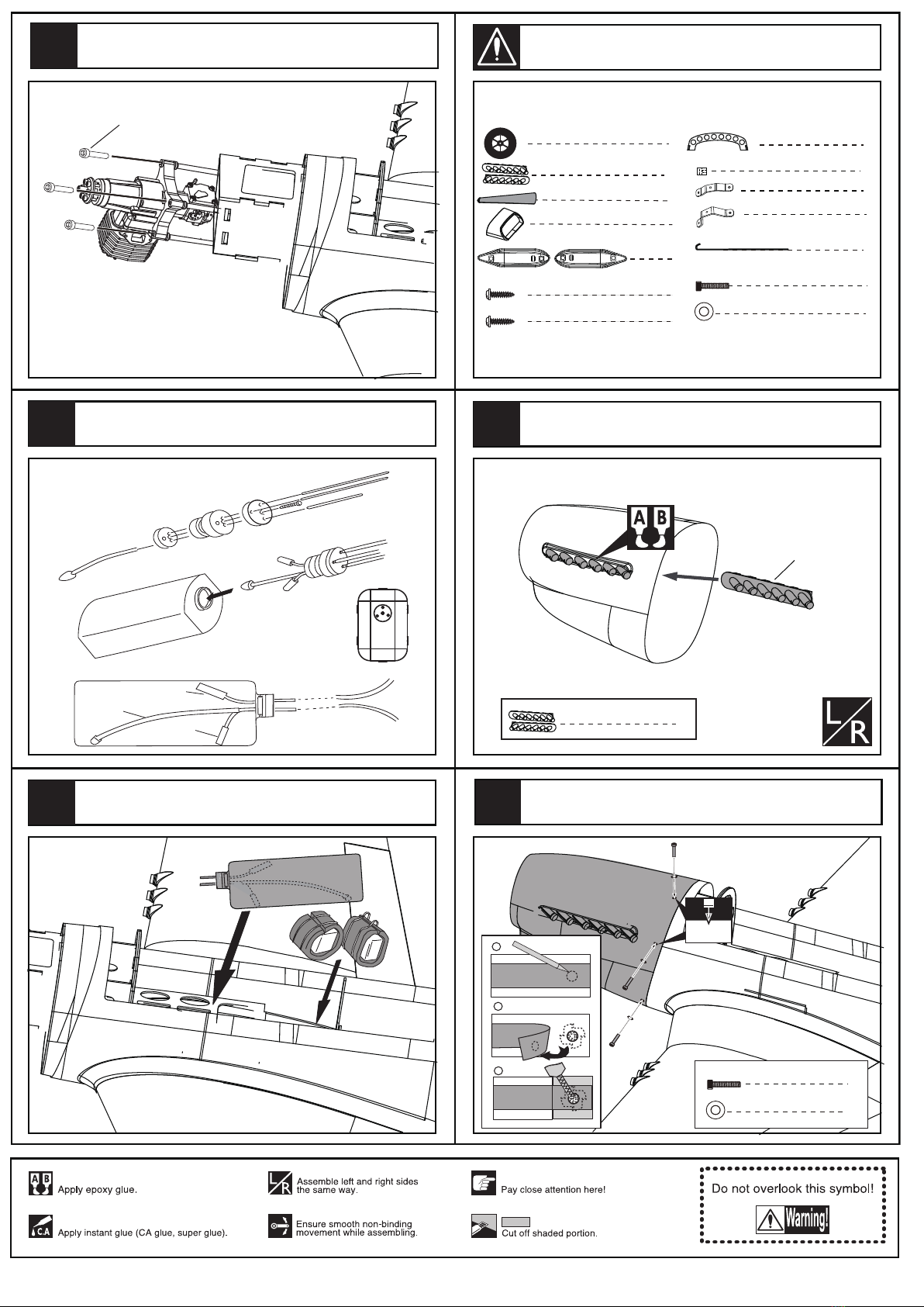
Top RC Model P-51D Mustang 89 inch User manual


Other manuals for P-51D Mustang 89 inch
1
Table of contents
Other Top RC Model Toy manuals

Top RC Model
Top RC Model Sport Jet Odyssey User manual

Top RC Model
Top RC Model Hurricane MKIIB Mounting instructions

Top RC Model
Top RC Model F9F Cougar User manual

Top RC Model
Top RC Model Sport Jet Aspire ARF User manual

Top RC Model
Top RC Model F-16 Fighting Falcon User manual

Top RC Model
Top RC Model Beechcraft Bonanza V35 User manual

Top RC Model
Top RC Model P-51D Mustang 89 inch User manual

Top RC Model
Top RC Model Focke-Wulf Fw190A-8 User manual

Top RC Model
Top RC Model Super galeb G-4 ARF User manual
Popular Toy manuals by other brands

Fisher-Price
Fisher-Price THOMAS & FRIENDS TRACK MASTER BUILDER BUCKET instructions

Mattel
Mattel Barbie L2940-0920 instructions

Viessmann
Viessmann 4114 Operation manual

GRAUPNER
GRAUPNER North American Harvard AT 6 Building instructions

The Handy
The Handy 5050 Assembly instructions

Lionel
Lionel 71-4094-250 owner's manual


