The Wings Maker Slick 540 User manual


Other manuals for Slick 540
1
Other The Wings Maker Toy manuals

The Wings Maker
The Wings Maker Wingman I User manual

The Wings Maker
The Wings Maker Wingsman II User manual

The Wings Maker
The Wings Maker ARF Ultimate EP User manual

The Wings Maker
The Wings Maker 1/4 SUPER CUB GA036 User manual

The Wings Maker
The Wings Maker FC-1 User manual

The Wings Maker
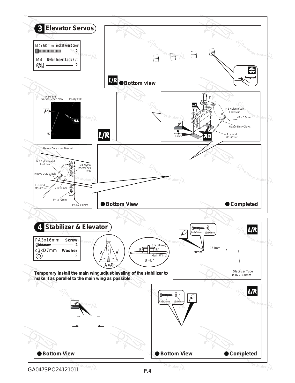
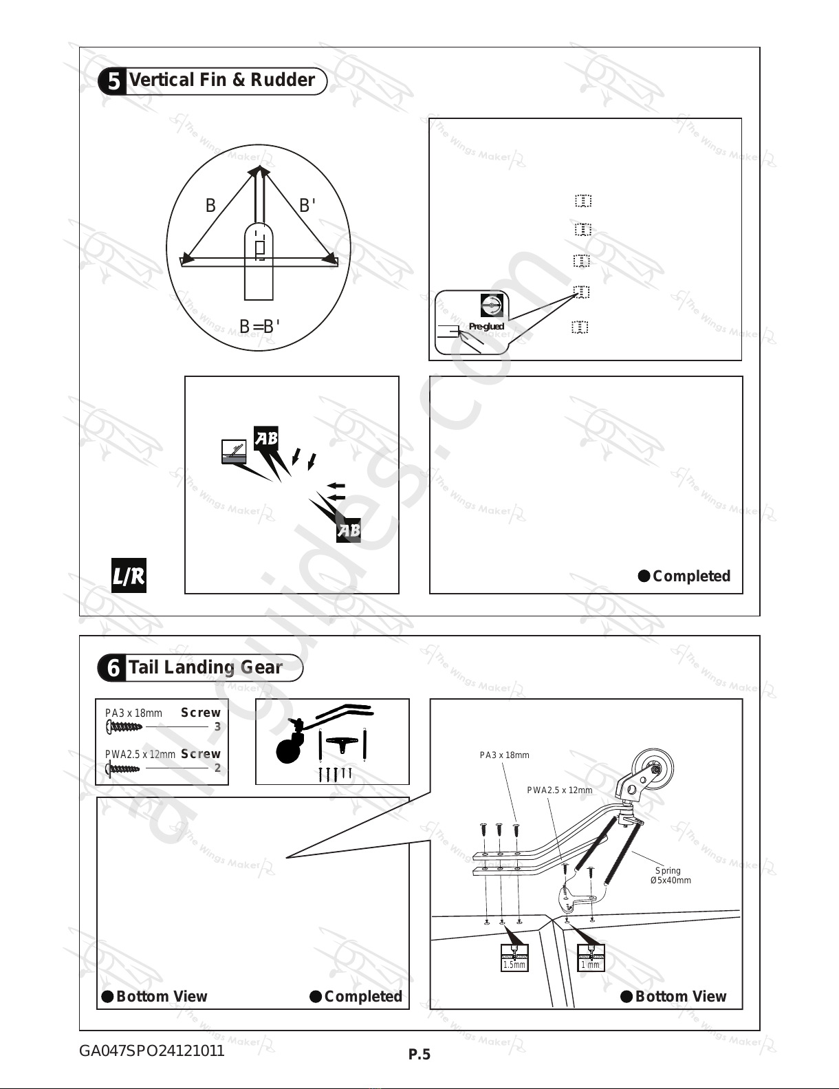
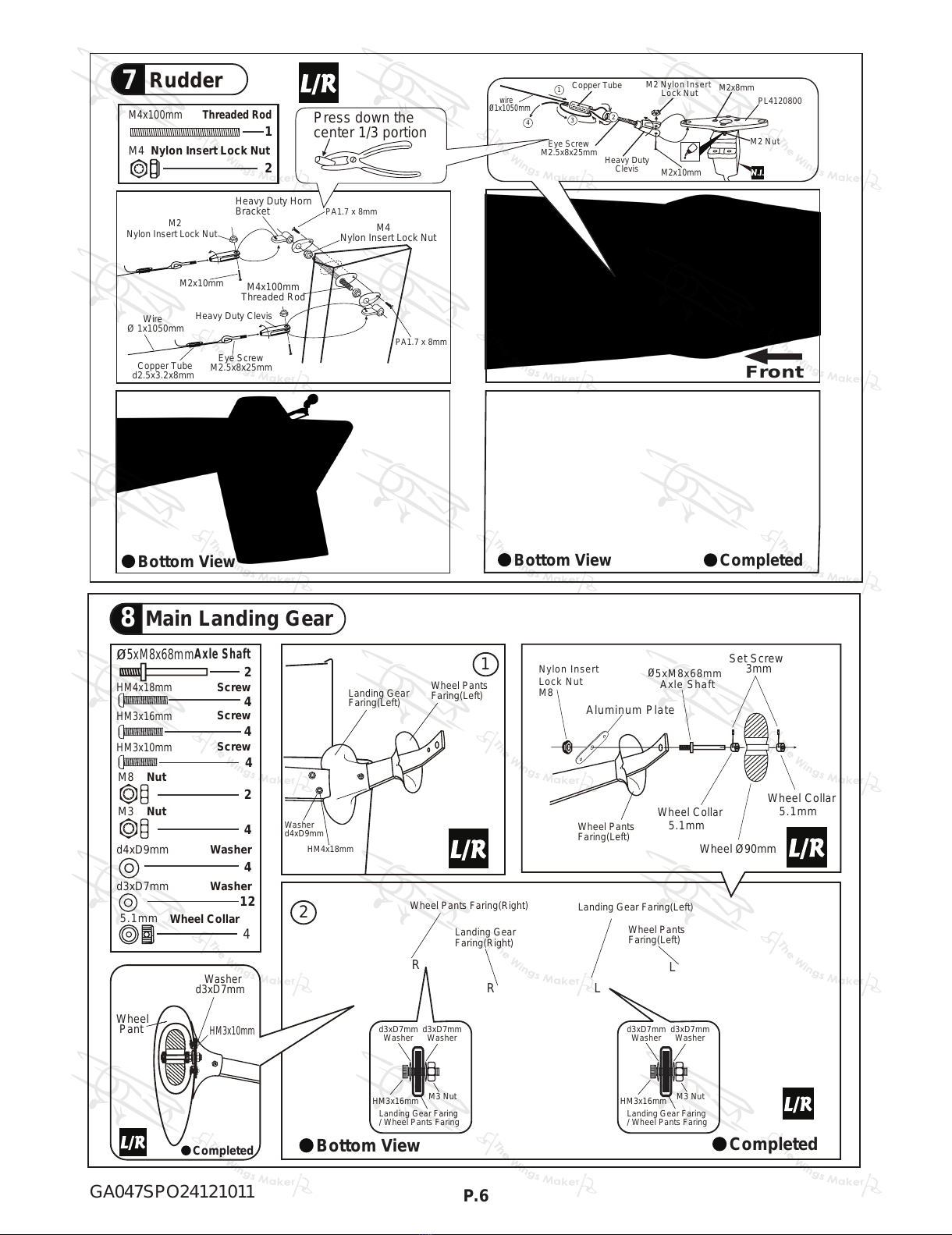
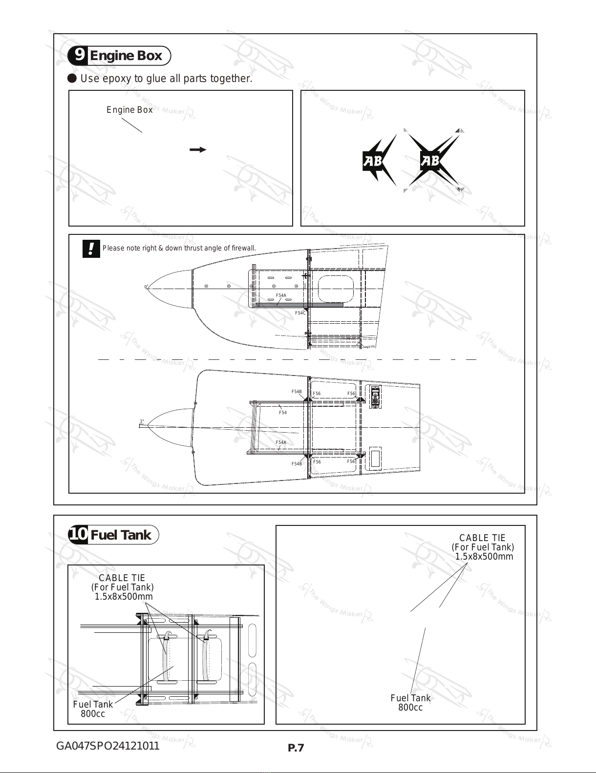
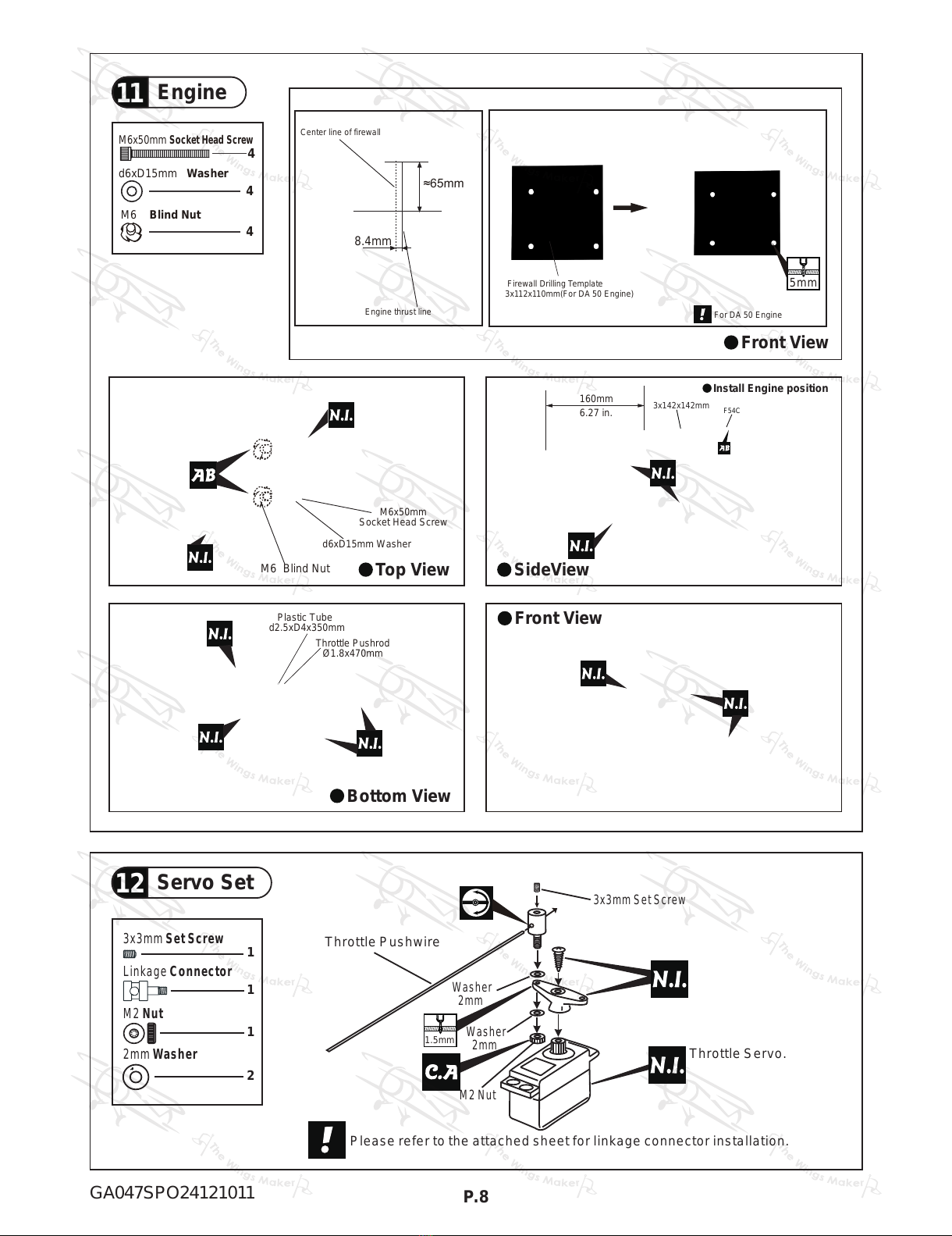
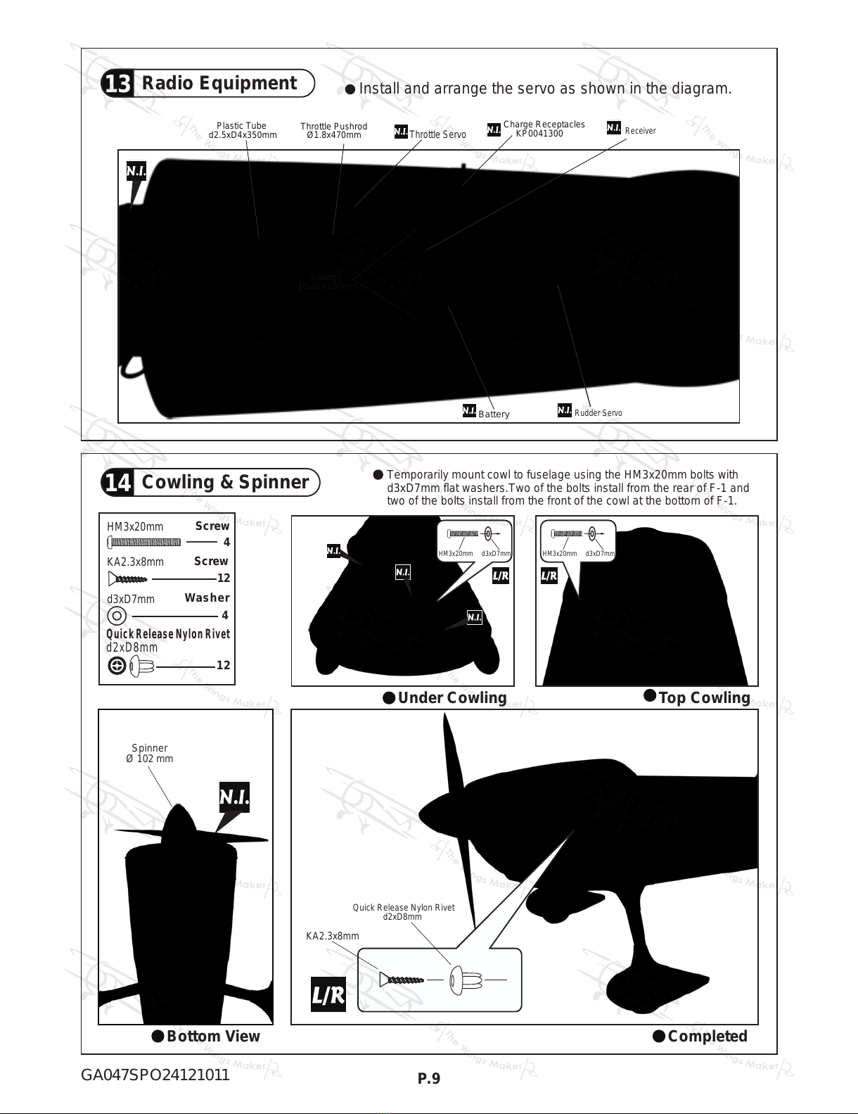
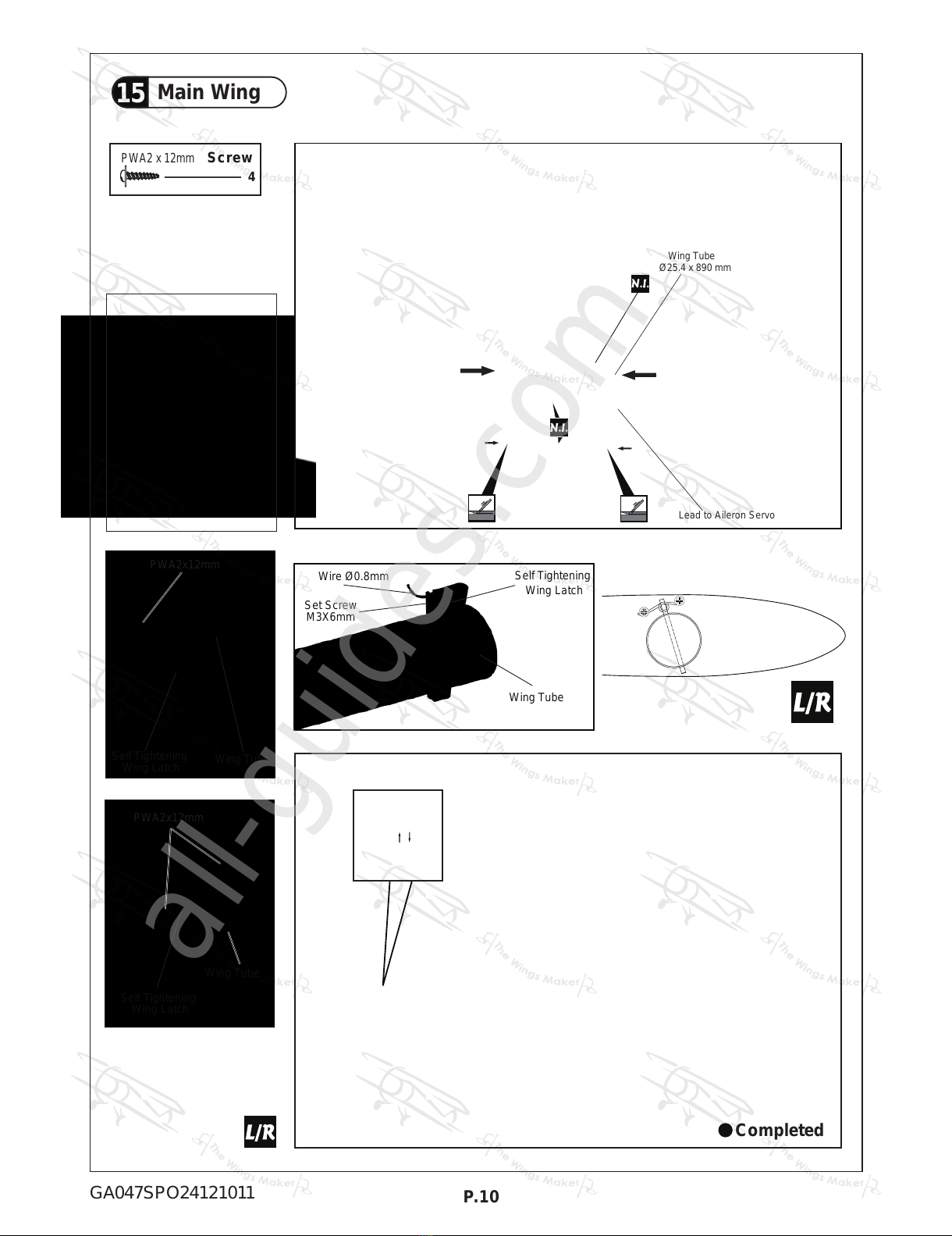
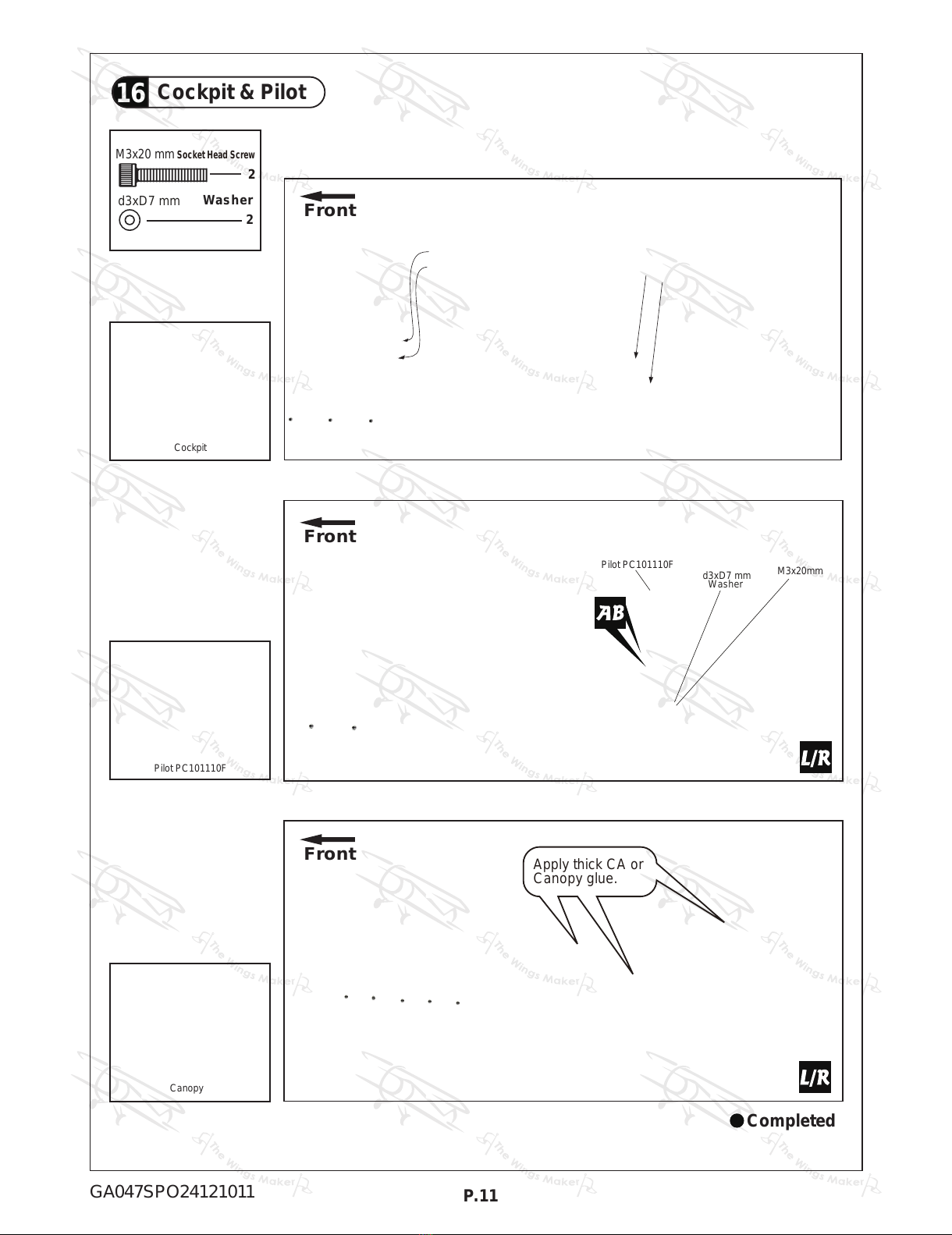
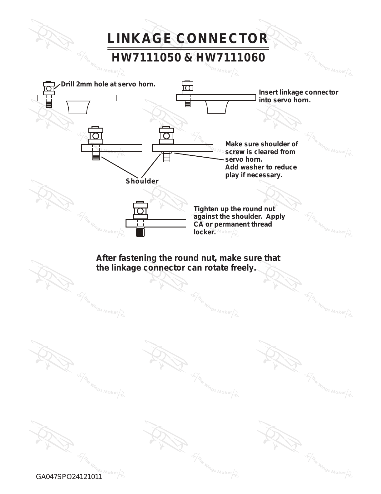
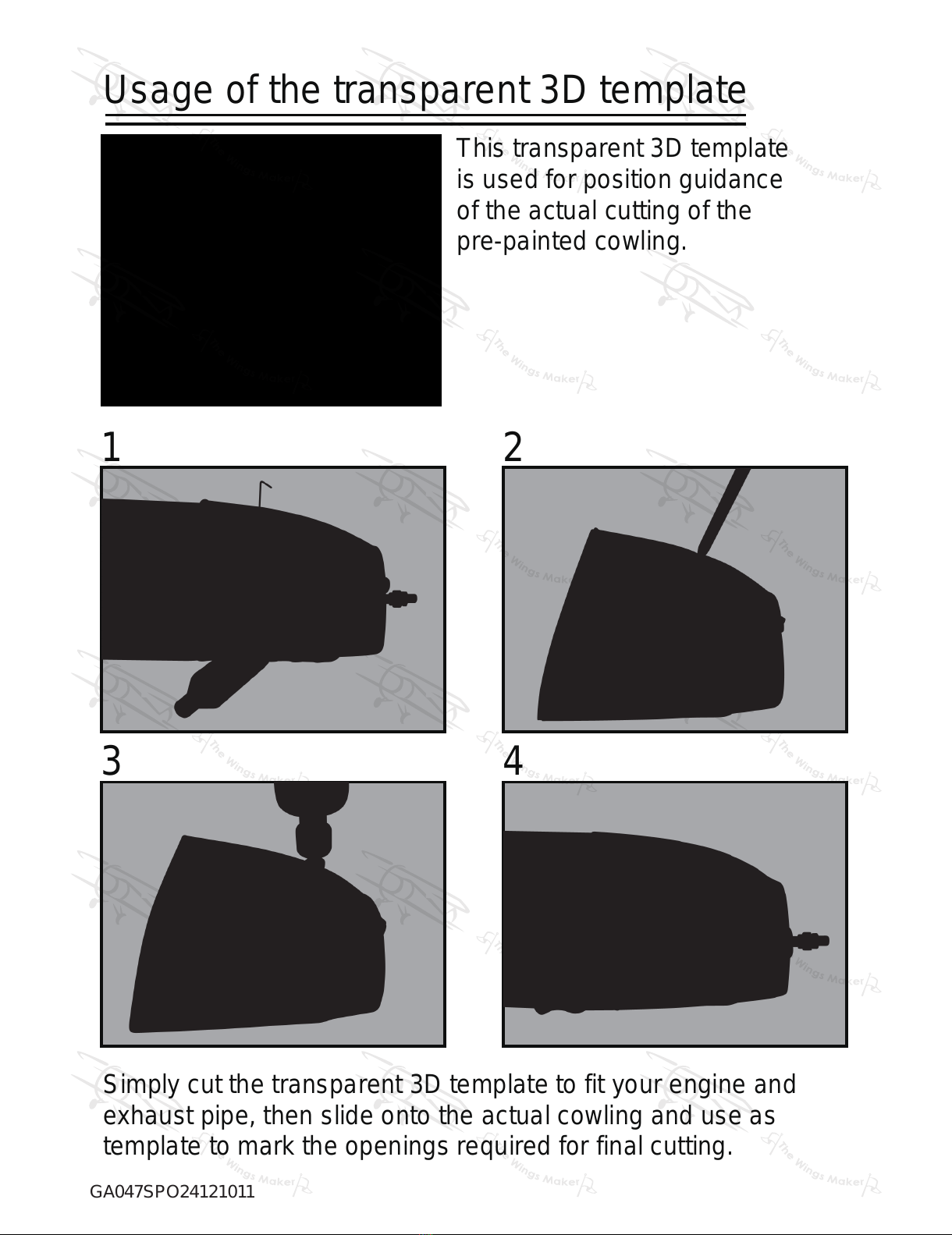
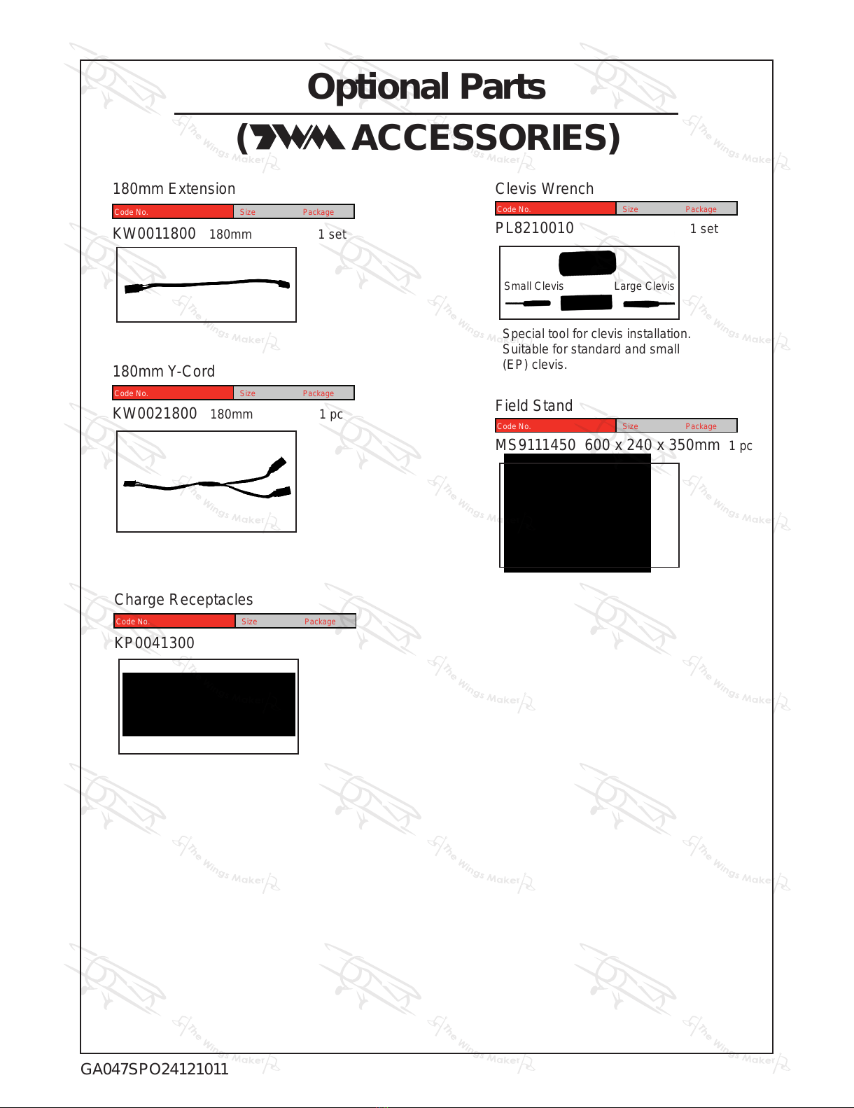
The Wings Maker Slick 540 User manual

The Wings Maker
The Wings Maker Piper J-3 CUB 26 User manual

The Wings Maker
The Wings Maker Wingman II User manual

The Wings Maker
The Wings Maker SPITFIRE 160 User manual

The Wings Maker
The Wings Maker Wingman I User manual

The Wings Maker
The Wings Maker DF-032 User manual

The Wings Maker
The Wings Maker SPITFIRE 160 User manual

The Wings Maker
The Wings Maker SkyNova 2 User manual

The Wings Maker
The Wings Maker Handyman Twins User manual

The Wings Maker
The Wings Maker FAIRCHILD PT-26 40 User manual

The Wings Maker
The Wings Maker Handyman EP User manual

The Wings Maker
The Wings Maker Spitfire EP User manual

The Wings Maker
The Wings Maker GM040P User manual

The Wings Maker
The Wings Maker CLIPPED WING CUB - 48 User manual

The Wings Maker
The Wings Maker CAP 232 46S User manual


Popular Toy manuals by other brands

Kids II
Kids II Oball GoGrippers Adventure Park Playset manual

Jamara
Jamara Jeep Wrangler JL Big Wheel instructions

roundhouse
roundhouse TALIESIN Owner's handbook

Hasbro
Hasbro zynga KRE-O CityVille INVASION MARINA MADNESS... manual

PIKO
PIKO BR 003 Instructions for use

Mega Bloks
Mega Bloks 3-in-1 Ride-On Firetruck instructions

FISCHER
FISCHER Fischertechnik PROFI SENSORIC manual

Fisher-Price
Fisher-Price M0411 Owner's manual with assembly instructions

Hangar 9
Hangar 9 Cap232 instruction manual

Shuang ma
Shuang ma 9100 instruction manual

Trackmaster
Trackmaster THOMAS' BUSY DAY Assembly instruction

Bachmann
Bachmann F3-A Dummy instructions


