Topgreener TDOS5 User manual

Vacancy Mode: Manual On
only, automatic Off after set
time delay.
Mode Position
INSTALLATION INSTRUCTIONS
TD0S5/ TD0S5-NL
OCCUPANCY/VACANCY
(2-IN-1)
SENSOR SWITCH
Voltage ................................................................................120VAC,60Hz
Incandescent ........................................................................................500W
Fluorescent...........................................................................................500VA
Motor ...............................................................................................1/8HP
Time Delay .......................................................................15Sec to 30Mins
Light Level. .........................................................................30 Lux--Daylight
Operation Temperature ............................................................32 F
-131 F
0
The passive infrared sensors work by detecting t he difference between
hea t emitted from the human body in motion and the background space.
The sensor switch can turn a load on and hold it as long as the sensor
detects occupancy. After no motion is detected for the set time delay, the
load turned off automatically.The sensor switch has one relay (equal to
single pole switch), also includes Ambient Light Level Sensor.
Coverage Area
The coverage range of the sensor switch is specified and illustrated in
Fi gure 1. Large objects and some transparent barriers like glass
windows will obstruct the sensor's view and prevent detection,
causing the li ght to turn off even if someone is still in the detection area
.
Description
OFF
Left
Circuit is permanently
opened. ( switched off)
Center
Occupancy Mode:
Automatic On, automatic
Off after set time delay.
VAC
Right
Push-Button
on Reaction
None
Manually toggles
On
I
Off load.
Manually toggles
On/Off load.
Time Delay knob
Default position: 15 Seconds (Test mode)
Adjustable: from 15 Seconds to 30 Minutes (clockwise)
Sensor Sensitivity Range Knob
Default position: Center at 65%
Adjustable: 30% (Position 1) to 100% (Position 4)
Note: Turn toward right for greater room space.
Ambient LightLLevel Knob
Default position: Daylight (100% at position 4)
Adjustable: Daylight to 30Lux (Counter clockwise)
Note: to avoid wasting energy by preventing light turn-on during
daylight.
1.
Connect lead wires as wiring diagram (see Figure 2): Black lead
to the Line (Hot), Red lead to the Load wire, White lead to the
Neutral wire, Green lead to the Ground.
Note: The white wire MUST be connected to the neutral wire in
the junction box. Please do not connect the white wire to any
other wire besides the neutral.
2.
Gently position wires in wall box, attach sensor switch to the box.
3.
Mount device "TOP" up.
4.
Restore power at circuit breaker or fuse. Wait
one
minute for
the sensor to complete its initial run.
5.
Remove the small cover plate. (Illustrated in Figure 3)
6.
Locate the adjustment knobs on the control panel to test and
change setting.(Illustrated in Figure 3)
7.
Replace the small cover plate after testing and setting.
8.
Attach the wallplate.
DESCRIPTIONION
IINSTALLATIONION
SAFETY WARNING::
Read and understand these instructions
before installation. This device is intended for installation in
accordance with the National Electrical Code and local
regulations. It is recommended that a qualified electrician
perform this installation. Make sure to turn off the circuit
breaker or fuse(s) and test that the power is off before wiring
the device.
Note: Please check the junction box for a neutral wire. This switch
requires a neutral wire in the junction box for it to work properly.
Wir ing Diagram:
ADJUSTMENT
BBand Switch Prescription
OCC
SPECIFICATIONS
Switch Type...................................................................................Single Pole

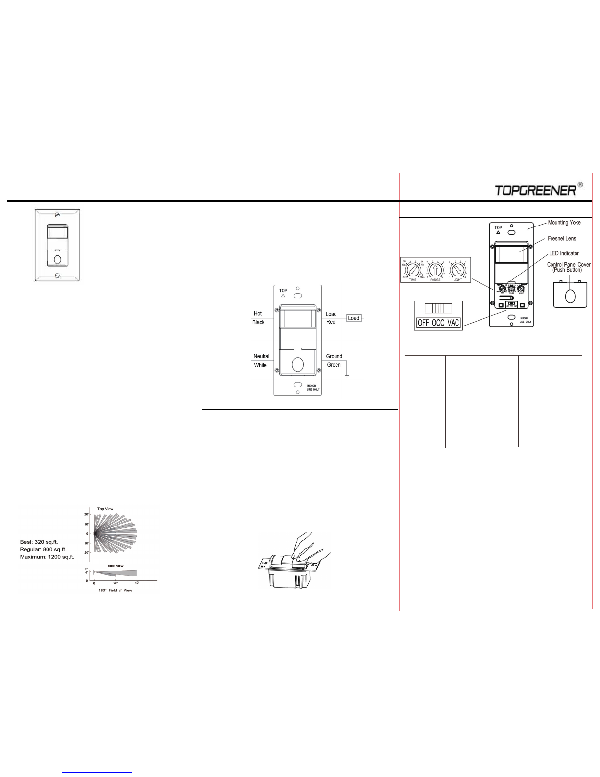
NOTE : For TDOS5-NL, the night light behind the Fresnel
Lens functions as follows:
OFF
---- The Night Light stays on;
OCC
---- The Night Light will not activate;
VAC
---- The Night Light will turn on when the load is off.
INSTALLATION INSTRUCTIONS
Use the band switch located under the control panel cover to select
the operation mode of the sensor switch. “OFF” mode powers off the
entire sensor. “OCC” mode automatically turns the load on and off
based on occupancy. “VAC” mode requires the load to be manually
turned on and will automatically turn off the load based on occupancy.
VAC mode can also be described as “Manual On Occupancy Mode”.
Manual On/Off Button
By Pressing the control panel cover, the Load can be turned On/Off
und er OCC or VAC mode. (Illustrated in Figure 5)
Turning On the Load under Occupancy Mode
Load will automatically turn on when occupancy is detected.
Turning On the Load under Vacancy Mode
Press switch cover to manually turn on the Load.
Automatically Turning Off the Load
Under either mode, the Sensor keep the Load on when no motion is
detected for up to the set time delay before automatically turning off
the load. Under VAC Mode, the Load will automatically turn back on if
motion is detected within the first 30 seconds.
Manually Turning Off the Load
you can manually turn off the load in OCC or VAC mode by pressing the
switch cover. In OCC mode, the sensor will take about 5 minutes to
reactivate and will not respond to motion suring this time.
Conversely, the Night Light will turn off when the load is on.
-04-
Figure 5
1.
It can take up to one minute for initial run to complete.
2.
Check the wiring connections, especially the
Neutral Wiring.
1.
There can be up to a 30 minutes time delay after the last motion
detected. To verify proper operation, turn the Time Delay Knob to 15s
(Test Mode), make sure there is no motion (no LED flashing), and
the Load should turn off in 15 seconds.
2.
Check if there is any significant heat source mounted within six feet (two
meters) that may cause false detection, such as a high wattage light
bulb, portable heater, or HAVC d evice.
3.
Check the wiring connections, especially the Neutral wiring to the
sensor switch.
The Load turns On when there is no motion
1.
Switch from
OCC
to VAC mode.
2.
Cover the Sensor Switch's lens to eliminate unwanted coverage area.
3.
Turn the Sensitivity Level knob to the left to avoid false alerts in
smaller rooms and if installed near the door way.
If within two(2) years from the date of purchase, this product fails due to
a defect in material or workmanship, we will repair or exchange it, at its
sole option free of charge. This warranty does not apply to: (a) damage to
units caused by accident, dropping or abuse in handling, acts of God or
any negligent use; (b) units which have been subject to un-authorized
repair, opened, taken apart or otherwise modified; (c) unit not used in
accordance with instruction; (d) damages exceeding the cost of the product;
(e) finish on any portion of the product, such as surface and weathering,
as this is considered normal wear and tear; (g) transit damage, initial
installation costs, removal costs, or rein-installation costs.
This warranty service is available by returning the product with proof of
purchase, purchase date and a description of the problem to the
dealer from whom the unit was purchased.
May, 2016
-06-
OPERATION TROUBLESHOOTING WARRANTY INFORMATION
To operate properly, the Sensor Switch consumes power from the hot
and
Neutral.
Therefore, a
Secured Neutral Wiring is required.
Initial run
The Sensor Switch requires an
initial run of one minute.
During the
initial run, the load may turn on and off several times.
Do not adjust any settings it until the initial run completed
The Load is out of control (frequently flashing)
The Load does not turn On when motion is detected
1.
Check to see if Ambient Light Level is enabled by covering the lens
by hand.
2.
Check the wiring connections, especially Hot and Neutral wiring, and
make sure there is no loose wiring.
The Load does not turn Off
-0
5
-
Other manuals for TDOS5
3
This manual suits for next models
1
Table of contents
Other Topgreener Accessories manuals
Popular Accessories manuals by other brands

Akida
Akida emp.2 Installation instructions manual

Troy Lee Designs
Troy Lee Designs UPV7855-HW Product owners manual

Lippert Components
Lippert Components Solera TI-278 Installation guides

Cygnett
Cygnett CY2962CHCSA user manual

Kompernass
Kompernass SilverCrest KH 205 operating instructions

Skywalker
Skywalker SAK140 user manual