Tormax 1102 User manual

T-1661 e 31.8.15
Translation of the original
instructions for use
Instructions for Use
For Automatic Swing Doors with Drive
TORMAX 1102 Swing Door Drive
TORMAX 1201 Swing Door Drive
Please follow the safety instructions in chapter 2!

2Instructions for Use TORMAX 1102, 1201 T-1661 e
First edition: 12.14, update 8.15
We reserve the right to make technical changes.
Printed on environmentally friendly paper bleached without the use of chlorine.
Landert Motoren AG and Landert GmbH are certified to ISO 9001.
Contents
1 General Information 3
1.1 Target Groups 3
1.2 Storage and Forwarding of the Manual 3
1.3 Area of Application 3
1.4 Explanation of the Symbols 4
1.5 Technical Data 4
2 Safety 5
2.1 Responsibilities 5
2.2 Use for the Purpose Intended 5
2.3 Pre-Conditions for the Operation of the System 5
2.4 Hazards and Risks 5
2.5 Checks 6
2.6 Decommissioning the System in the Event of a Fault 6
2.7 Disposal 7
3 Product Description 8
3.1 System Overview 8
3.2 System Function 10
3.3 Operating Modes 12
4 Operation 14
4.1 Commissioning 14
4.2 Operation with the TORMAX User Interface 14
4.3 Setting Customer Parameters with the TORMAX User Interface 15
4.5 Operation on Power Failure 17
4.6 Resetting the Panic Fitting 17
5 Procedure in the Event of a Fault 17
6 Maintenance 18
6.1 Cleaning 18
6.2 Functional Checks 18
6.3 Maintenance and Testing 18
7 Appendix 19
7.1 Fault Table 19
7.2 Check-List for Functional Checks 21
Declaration of Conformity 23

Instructions for Use TORMAX 1102, 1201 T-1661 e 3
1 General Information
1.1 Target Groups
• Operatoroftheautomaticswingdoor.Theoperatoristhepersonresponsiblefortheoperationand
maintenance of the system.
• Personsinstructedbytheoperatortocarryoutcertainduties,forexampletheservicingandmain-
tenance of the automatic swing door.
1.2 Storage and Forwarding of the Manual
• Storetheinstructionsforuseinthevicinityof theautomaticdoorsystem.
• Ifthemanualhasbecomeillegibleduetoconstantusage,reordertheinstructions.
For download and print out see also: www.tormax.com/en/7/architects.html
• Whenthedoorsystemistransferredorresaledtoathirdparty,passthefollowingdocumentsto
the new owner:
– This instructions for use
– Documentation concerning modification and repair work
– Proof of the regular examinations System test book T-879
1.3 Area of Application
Warning
Inappropriate Use
Risk of injury to persons
• Usethisdoordriveonlywithswingdoors.
Product name, door system: Automatic swing door (single or double-leaved)
Product name, door drive: TORMAX 1102 Swing Door Drive
TORMAX 1201 Swing Door Drive
Serial number: ………………………………………
The identification plate with
the serial number is placed
on the drive itself under the
casing.

4Instructions for Use TORMAX 1102, 1201 T-1661 e
<
1.4 Explanation of the Symbols
Warning (signal word)
Source of hazard (designates a possibly hazardous situation)
Possible consequences of non-observance
• Measuresforavertingdanger.
Text which is highlighted in grey MUST be observed to ensure that the system operates perfectly.
Failure to observe these sections can cause damage to equipment.
Functions marked with this symbol are the factory setting. However, they can be reprogrammed
by a specialist.
Optional components which are not present in all systems.
1.5 Technical Data
Drive type Electromechanical swing door drive with DC motor
Control system Microprocessor 32 Bit
Mains connection 1 x 230 / 1 x 115 V AC, 50 – 60 Hz, 10 A
Power consumption 3 … 200 W
Sensor supply 24V DC 1,5A
Protective class, drive IP20
Ambient temperature –20 °C to +50 °C
Fuse 5 AT
Drive weight
TORMAX 1102 11,2 kg
TORMAX 1201 11,8 kg
Noise emission level < 70 db (A)

Instructions for Use TORMAX 1102, 1201 T-1661 e 5
2 Safety
2.1 Responsibilities
For instructing the operator: A skilled person from a TORMAX sales partner
For operating the system: The operator or a person instructed by the operator
For maintenance and function control: The operator or a person instructed by the operator
For annual testing and approval: A skilled person authorised by the manufacturer
Skilled persons are persons who have adequate knowledge in the field of power-operated doors as a
result of their specialist training and experience and who are so familiar with the relevant health and
safety regulations, guide-lines and generally recognised codes of practice that they are able to assess
the condition of power-operated doors with regard to the safety of their operation.
Maintenance of electrical parts must be carried out by a trained electrician.
2.2 Use for the Purpose Intended
The automatic swing door is intended exclusively for use in dry premises in areas used as a pedestrian
thoroughfare and only within the specified technical data. Special techniques can also be used to attach
the drive unit to the building envelope. Technical modifications of the system must only be carried out
by skilled person. Any other use or extended use is considered to be improper and may result in danger
for body and life.
2.3 Pre-Conditions for the Operation of the System
The door system was designed, installed and checked for functionality and safety by skilled persons
prior to hand-over to the operator. The company responsible for the system’s installation instructed the
operator on the system’s use and maintenance as well dangers associated with the system operation.
The operator has confirmed this by his signature in the system test book T-879.
The provisions imposed by law, health and safety and occupational health regulations for the avoidance
of accidents and the protection of the environment which are generally applicable in the country in
which the system is operated supplement the Instructions for Use.
• ReadtheInstructionsforUsecarefullybeforecommissioningtheautomaticswingdoor.
• Onlyusethesystemwhenitisinperfectworkingorder.Theoperatingconditions,inspection
and maintenance intervals stipulated by the manufacturer must be observed (section 6).
• Safetyfacilities(e.g.sensortechnology,protectingcovers)mustnotberemovedordisabled.
• Arrangetohaveanyfaultsrectiedimmediatelybyaskilledperson.
2.4 Hazards and Risks
Depending on the system design
and equipment, there is a residual
risk of crushing, shearing and colli-
sion with limited force in the move-
ment area of the door leaf. T1661_3

6Instructions for Use TORMAX 1102, 1201 T-1661 e
Warning
Danger through moving parts:
– in the area of all closing edges (especially hinge)
– in the region of the linkage lever
– when objects such as, for example, display shelves are erected in the direct proximity of
the moving part of the door leaf.
Risk of injury
• Donotallowchildrentoplayinthedirectproximityoftheautomaticdoor.
• Childrenmaynotoperatetheexistingoperatingunits.
Warning
Hazards can arise due to deliberate damage, incorrect installation, defec-
tive sensors or sensors which are longer properly adjusted, sharp edges,
incorrectly mounted and defective casing or missing covers.
Danger for body and life, danger of injury
• Havesystemrepairedbyaqualiedperson
2.5 Checks
The regular checks and examinations set out in Chapter 6 must be carried out as instructed by the
manufacturer. The manufacturer recommends that a maintenance contract be concluded in order to
operate the system safely and to maintain its value for as long as possible.
2.6 Decommissioning the System in the Event of a Fault
If there is a fault the automatic swing door may only be taken out of service by a skilled person, the
operator or a person who is instructed to do so by the operator. This must be done on all occasions on
which the safety of persons could be compromised.
• Disconnectthesystemfromthepowersupply.
• Takethesystemoutofservicebyaskilledpersonifoperatedwithbatteryunitu.
• Selectoperatingmode“P”if thesystemcontinuestooperateusingtheinternalemergencypower
supply (see section 3.3 for operating modes).
• Openthedoormanuallyandsecureintheopenpositionifitisinstalledinanescaperoute.
• Firedoorsmustneverbesecuredintheopenpositioneveninemergencies.
See section 7 for rectification of faults.

Instructions for Use TORMAX 1102, 1201 T-1661 e 7
2.7 Disposal
This system must be properly dismantled at the end of its working life. Its disposal must comply with
national regulations. We recommend that you contact a skilled person disposal company.
Warning
Aggressive acids
Risk of injury if you dismantle the battery module.
• Disposeofbatteriesproperly.
Warning
Flying around parts
The tensioned spring represents a hazard when dismantling the drive.
• Beforeopeningthecasing,releasethetensiononthespringuptothestop.
Warning
Broken glass
Risk of injury when dismantling the door leaves.
• Takecarewhentransportingthedoorleaves.

8Instructions for Use TORMAX 1102, 1201 T-1661 e
3 Product Description
3.1 System Overview
Single Leaf Systems
Double-leaved Systems
HK
GK
7b
6a
6b
10a 3b
3b
T1661_1e
7a
5a
HK
GK
1a,b 2a
3
1c
10b,c
4a 4b 4c
5b 8b
4a
4b
4d
8a 8c 9
inside outside
inside
3b
3b
T1661_7e
7a
7a
5a
10a
HK
NK NK
1a,b 2a 1a,b
3 3
1c 1c
2b
2c
10b,c
4a 4b 4c 4e
5b 8b
4a
4b
4d
8a 8c 9
Primary drive Secondary drive

Instructions for Use TORMAX 1102, 1201 T-1661 e 9
1 Drive a) Motor and spring unit
b) MCU42 control system with monitoring system, power limitation and
permanent diagnosis.
£Controlled closing function of the door in power-off condition
£Controlled opening function in power-off condition
c) Linkage / sliding lever
2Drive accessories ua) £Emergency power supply via the battery unit
b) £Mechanical door coordinator for double-leaf doors
c) £Driver flap to the mechanical door coordinator
£…
3 Door leaves a) Swing leaf with main closing edge (HK) and secondary closing edge (NK)
b) £Finger protection to enhance the safety of the secondary closing edge.
4Operating controls a) £User interface with 5 operating modes and fault display
b) £Operating mode switch with 3 positions.
c) £Lock for the user interface
d) £Remote control of operating modes
e) £Switch for 1-leaf operation
5Internal activators a) With automatic activation b) With manual activation
£Radar with/without direction recognition £Push button
£IR motion detector £Contact-free button
£Contact mat £Button for passage with bed
£… £…
6External activators a) With automatic activation b) With manual activation
£Radar with/without direction recognition £Key switch
£IR motion detector £Card reader
£Contact mat £Remote control
£… £Button for passage with bed
£… £…
7Safety sensors a) £Presence sensor safeguarding the swing area when closing
b) £Presence sensor safeguarding the swing area when opening
£…
8Emergency systems a) £Power switch / fuse
b) £Emergency-off switch
c) £Fire alarm system
9Output message £Bell / gong
£Door status
10 Lock ua) £Electrical door opener
b) £Door handle
c) £Mechanical door lock
£Depending on the system’s equipment

10 Instructions for Use TORMAX 1102, 1201 T-1661 e
3.2 System Function
The operator of the door system is responsible for
ensuring that the automatic swing door is freely ac-
cessible at all times. The operator must particularly
ensure that the swing area of the door leaves is not
obstructed by any objects.
Automatic Door Operation with Sensors
When operating automatically (operating mode AUTOMATIC) the door is automatically opened from
both sides by sensors when a person approaches. A key switch uor card reader unormally allows
access from outside when the door is in operating mode EXIT or OFF. The door unlocks u, opens and
closes again as soon as no further sensors are activated after a hold-open time which is set sepa-
rately.
Double-leaved doors open at the same time or, in the case of overlapping door leaves, in sequence.
Closing must be in the correct closing sequence and, for reasons of safety, one after the other.
Door Leaf Protection
The safety devices are selected and installed by the installation company in line with general and
country-specific standards, guide-lines and requirements.
System with Full-Energy Mode
The door leaves are equipped with safety sensors on the leaves. The safety sensors prevent a person
in the operating radius of the leaf from being hit by the leaf. If one of the safety sensors should fail, the
system switches to safety mode. The door can still be opened but only manually. In the case of low risk
systems, the system switches to emergency mode. The door leaf still moves but only slowly and in
Low-Energy mode. If the safety device fails in the closing direction, the door remains open for 30 seconds.
Systems with Low-Energy Mode
Hazards due to impact and crushing are minimised by restrictions on speed and force. Thus the system
provides a high degree of safety.
The system offers maximum ease of use and safety if it is equipped with additional safety sensors.
Semi-automatic Operation with “Push-and-Go”
Instead of having sensors the door can be manually pushed open. After being detected by the control
system, the door opens automatically and closes again.
Manual operation with Power Assist
InoperatingmodeP“Manualoperation”ordependingontheexactsettinginAUTOMAT,thedoorcan
beeasilyopenedmanuallywith“PowerAssist”.Afteropening,thedoorremainsintheholdopenposi-
tion before it closes automatically using little force.
Dependingontheconguration,“PowerAssist”canbeactivatedinadvanceforalimitedperiodusing
a button, door trap sensor or a motion detector. In this case the door can be easily opened with very
little effort.
T1540_12

Instructions for Use TORMAX 1102, 1201 T-1661 e 11
Traffic Control
Movement through the door can be allowed in only one direction if desired (operating mode EXIT) or
completely blocked (operating mode OFF).
Double-leaved systems can also be operated as single leaf doors by means of the single leaf operation
switch.Inthiscasebothdoorscanonlybeopenedbymeansofthekeyswitchorthe“bedmovement”
switch.
Automatic System Monitoring
The control system monitors the safety sensors by a cycle of active tests. The control system also
conducts continuous internal system tests. If a safety-related component should fail, the system auto-
matically switches into a safe condition. At the same time the fault number is displayed on the user
interface. The operating mode currently displayed also flashes. You can find further information on this
subjectinsection5“ProcedureintheEventofaFault”.
Economy power mode
Economy power mode is activated as standard. This mode consumes less power in the non-operative
state.
The illumination on the user interface and most sensors are automatically switched off when not in use.
Electric Lock u
The system can be locked in the closed position by means of an electric lock u.
Operation in the Event of a Power Failure
Depending on the equipment installed, the following functions are possible:
– Controlled closing using the integral spring. The door can be opened manually by means of the
door handle (unlocking).
The door then closes again in a controlled manner using the integral spring.
The closing sequence is maintained in double-leaved doors by the use of a mechanical door coor-
dinator.
– Controlled opening using the integral spring. The door remains open.
– Continued operation for a certain period in the current operating mode by means of a battery unit u.
– Unlocking and opening of the door from outside by means of a key switch and the battery unit u.

12 Instructions for Use TORMAX 1102, 1201 T-1661 e
3.3 Operating Modes
The automatic door system can be operated with the TORMAX user interface u(5 operating modes
and status display) or with an operating mode switch u(3 operating modes).
Operating Mode OFF
The internal and external sensors are disregarded. The door is mechanically held in the closed position
and locked using an electric lock u. Access is only possible using the key switch or if the door is
manually unlocked using a key or the door handle is used to open the door manually.
The door can still be used for 5 seconds after selecting operating mode OFF. The door then locks at
the end of this period as soon as it is closed. The transition is signalled on the user interface by the
flashing display of operating mode OFF.
Operating Mode AUTOMATIC
The operating mode AUTOMATIC is normally used during the day. The door opens automatically through
the inside and outside sensors. The door can behave differently depending on the settings programmed
during commissioning:
“Push-and-Go”
If the door is manually pushed in the opening direction, it reacts as if to a command to open: it opens
automatically, waits for the hold-open time and then closes.
Systems with an Electric Door Lock u
The lock unlocks on every valid opening impulse. The door lock must be manually unlocked with the
doorhandlebeforeitispossibletoopenthedoorwiththe“Push-and-Go”system.Inthisoperating
mode the door lock can also be permanently unlocked depending on the setting programmed at the
time of commissioning.
Operating Mode EXIT
Operating mode EXIT is normally used for the period before the shop or office closes. The door will
only open automatically when activated by the internal sensor. When the door opens the external sen-
sor is also monitored for safety reasons. The open position is determined by the preceding selection
of the operating mode AUTOMATIC. Additionally the door can be locked automatically by the door
lock u.The door lock can be permanently unlocked in this operating mode in case of need.
Operating Mode OPEN
The door opens and remains open. The open position is determined by the preceding selection of the
operating mode AUTOMATIC. The door opens again on receiving the next open impulse or when
changing the operating mode to OFF and back again to OPEN.
Operating Mode Manual Operation
The door leaf can be freely moved. This operating mode can be used for cleaning the door leaf or for
temporarily shutting down the door. The system is reset after leaving this operating mode. On each
opening command In this operating mode the door lock is unlocked during 10 s.
After a single leaf of a double leaved door has been opened manually, the closing sequence is main-
tained mechanically by means of a mechanical door coordinator. If there is no mechanical door coor-
dinator, the door leaves can be opened manually independently of each other without regard to the
overlap on the door leaves.
P

Instructions for Use TORMAX 1102, 1201 T-1661 e 13
Single Leaf Operation Switch
– Secondary leaf on
If an opening command is given or in the event of Push & Go, both leaves always open.
– Secondary leaf off
If an opening command is given via the internal or external sensors or by Push & Go, only the primary
leaf.If anopeningcommandisgivenbythe“passageforbeds”buttonorthekeyswitch,bothdoors
are opened.

14 Instructions for Use TORMAX 1102, 1201 T-1661 e
4 Operation
The automatic swing door may only be operated by a skilled person, the operator or a person in-
structed by the operator.
4.1 Commissioning
Before switching on the mains power supply:
• Unlocktheoptionalmechanicaldoorlock.
• Checkthatthe movementareaof thedoor leavesis freefrom obstructionssuch asracks,plant
containers, umbrella stands ect.
• SwitchonthemainspowersupplyandselectoperatingmodeAUTOMATIC,forexample.
The door is now ready for operation.
4.2 Operation with the TORMAX User Interface u
TORMAX User Interface Lock ufor User Interface
The display is switched on by pressing the selector button briefly.
www.tormax.com
1
2
3
4
1
1
0
T1427_4
T1661_2e
OFF
AUTOMATIC
not assigned
OPEN
EXIT
Operating mode
symbols
Manual operation
Door electrically
locked
Selector key 2,
downwards
Selector key 1,
upwards
Unlocking of Operating Unit
The operating unit can be protected against unauthorized access by way of the lock uor the code lock.
• Unlocklock=position0
or
• Entercode…/…/…usingoperatingunit.Standardcode=3/3/3.Thecodecanbedetermined
by the engineer.
Example with code 3 / 3 / 3. Press upper selection button 3 times, then press the lower selection but-
ton 3 times and the upper selection button within 15 s . In case of entering wrong code: Wait at least
5 s . After successfully entering the code, the operating unit will be released within 60 s. The type of
operation can be adjusted. Access will be automatically blocked again for 60 s after the button has
been pressed for the last time.
Selection of Operating Modes
• Pressselectorkeys1or2briey.Thecorrespondingoperatingmodesymbolisilluminated.

Instructions for Use TORMAX 1102, 1201 T-1661 e 15
Fault Display
E.g. H31 or E42 See section 7 for the meaning of the display.
• Resetbypressingtheselectorkey2briey.
Resetting the System
• Presstheselectorkey2foratleast5seconds.
The software is restarted. On double-leaved systems the software is restarted automatically on both
drives.
4.3 Setting Customer Parameters with the TORMAX User Interface
The company undertaking the installation reserves the right to restrict access to all or some of the
customer parameter settings. If the user interface is in an area accessible to the public it must be
protectedagainstthirdpartyaccessbya“codelock”ora“lockfortheuserinterface”.
Access level “U” for customer parameters
T1661_10e
Uappears, ready for programming
Confirm with
key 2
P
T1661_11e
Zero appears as first digit of code
P
Enter first code
digit with key 1
Confirm with
key 2
T1661_9e
Indication of operating mode
Press keys 1 and 2
simultaneously until
«U» appears
P
Enter the three digit code for parameters
• Similarly,selectandconrmthesecondandthethirdcharactersofthecode.
If“C”appears,accessisblocked.Parameterscannotbere-setinthiscase.

16 Instructions for Use TORMAX 1102, 1201 T-1661 e
Parameters for displays
012 Drivetype(1=1102,2=1201)
042 Firmware version
043 Number of cycles
044 Number of operating hours
Parameters for settings
10 0…E Hold open time for activator inside / outside
0 / 1/ 2 / 3 /4 / 5 / 6 / 8 /10 /12.5 /15 /17.5 /20/40/ 60 s11 0…E Hold-open time button e.g. for beds
12 0…E Hold-open time for key switch
13 0…9 Delay for operating mode OFF (selection via
user interface) 1/ 3 /5 / 7.5 /10 /15 /20 /30 /45 / 60 s
14 0…9 Bell active time 0 / 0.5 / 1 / 2 / 3 / 4 / 5 / 6 / 8 / 10 s
20 0…6 Opening speed 10 … 100 %
21 0…6 Closing speed
301…3/6 Power limit when opening
Maximum depends on the drive type
311…3/6 Power limit when closing
321…3/6 Power limit when closing before the door is
closed
38 0…6 Starting angle for Push & Go / Power Assist 1/ 2 / 3 / 5 / 8 / 12 / 16 degrees
39 0…5 Starting angle for Push & Close Maximum / 8 / 10 / 12 / 14 / 16 degrees
80 0…2 Bell trigger Activator outside / activator inside / key switch
81 0…4 Button press time (detection delay for activator) 0/1/2/3/5
91 0…4 Code lock for user interface Switched off / code 111/... 222 /… 333 /…123
Command
040 Software reset
4.4 Operation with an Operating Mode Switch u
Selection of Operating Modes
The switch position defines the operating mode.
T1305_4
OFF
AUTOMATIC
OPEN
Resetting the System
– Change the operating mode in the event of a fault
or
– Cut off power supply to the system for at least 5 seconds.

Instructions for Use TORMAX 1102, 1201 T-1661 e 17
4.5 Operation on Power Failure
Opening a Door using a Key Switch uwith aBattery Unit u
• Turnthekeyswitchtothe“on”positionandholdinplaceforatleast5seconds,thenturnthekey
to the original position.
Thebatteryisactivatedusingthe“wakeup”function.
Thekeyswitchmustnotremainpermanentlyinthe“on”opposition.
The door is unlocked and opened.
The battery switches off again after the time programmed <by the installation engineer or
when the battery is fully discharged.
If required, the operating mode can be changed on the user interface during the wake-up.
4.6 Resetting the Panic Fitting u
• SelectoperatingmodeOFF(operatingmodeswitch, user interface ) or disconnect the drive from
mains (installation switch, mains plug).
• Pushthedoorleafbackintotheinitialposition.
• ChooseoperatingmodeAUTOMATICorswitchondriverespectively.
5 Procedure in the Event of a Fault
Faults are evident from abnormal door behaviour and/or as a fault display on the user interface. Fault
displaysontheuserinterfacetaketheformof aashing“E”or“H”followedbytwogures.
H=notication>thesystemcancontinuetobeused.
E=fault>thesystemisstationary.
Some faults or notifications can be rectified by restarting the door drive with a software reset and/or
briey(>10s)disconnectingthesystemfromthepowersupply.
Fault Display and Reset Using the TORMAX User Interface
See the table in section 7.1 for an overview of the fault displays.
Browse through the fault display using selector key 1 upwards
(to display several faults).
1. Reset the fault display, press selector key 2 (downwards) briefly.
2. Software reset: press the key for 5 seconds.
Reset of the Fault with the Operating Mode Switch
Software reset in the event of a fault: change the operating mode.
Reset of the Fault by Disconnecting the Power Supply
If the system does not have a battery unit, disconnect from the power supply for about 10 seconds.
If this does not reset the fault or if it re-occurs after a short time, you must arrange for the fault to be
rectified by a skilled person from your TORMAX dealer. In this case note the fault number and inform
the dealer. See the last page or the service tag on the system for the dealer’s address.
T1305_5
T1305_4

18 Instructions for Use TORMAX 1102, 1201 T-1661 e
6 Maintenance
The system was tested and approved by a skilled person before initial commissioning. The manufac-
turer recommends that you conclude a service contract in order to maintain the value of your system
for as long as possible as well as to ensure the system operates reliably and safely for a long time.
Only genuine TORMAX spare part should be used. The manufacturer accepts no liability if you fail
to observe this requirement. Original spare parts and original accessories guarantee the safety of
use in accordance with norm EN 16005.
The following maintenance work must be carried out:
6.1 Cleaning
Warning
Closing doors can crush – danger!
Trapped limbs can lead to serious injury.
• ThesystemmustonlybecleanedinoperatingmodeOFF,OPENorManualOperation.
• Cleancasingparts,theuserinterfaceanddoorleaveswithadampclothanda
commercial cleaner.
6.2 Functional Checks
The operator must check the function and safety devices of the automatic swing door at least
every three months. This will ensure that faults or hazardous changes in the system are detected
atanearlystage.Seesection7.2“Check-listforFunctionalChecks”foritemstobechecked.
You should arrange for any defects detected during the routine checks to be rectified immediately by
a TORMAX dealer (see the last page of this Manual for the address).
Warning
Potential switching malfunction in the automatic swing door.
Potential hazards – injury caused by impact or crushing.
6.3 Maintenance and Testing
Maintenance and testing should only be carried out by a trained skilled person following the manufac-
turer’s instructions.
Maintenance Interval
The maintenance interval depends on the frequency of use but the system must be maintained at
least once per year.
Scope of the Maintenance Work
The content of the maintenance work is specified by the manufacturer in an inspection list.
System Test Book
The test findings are recorded after the test in the system test book. The operator must keep it in a safe
place.

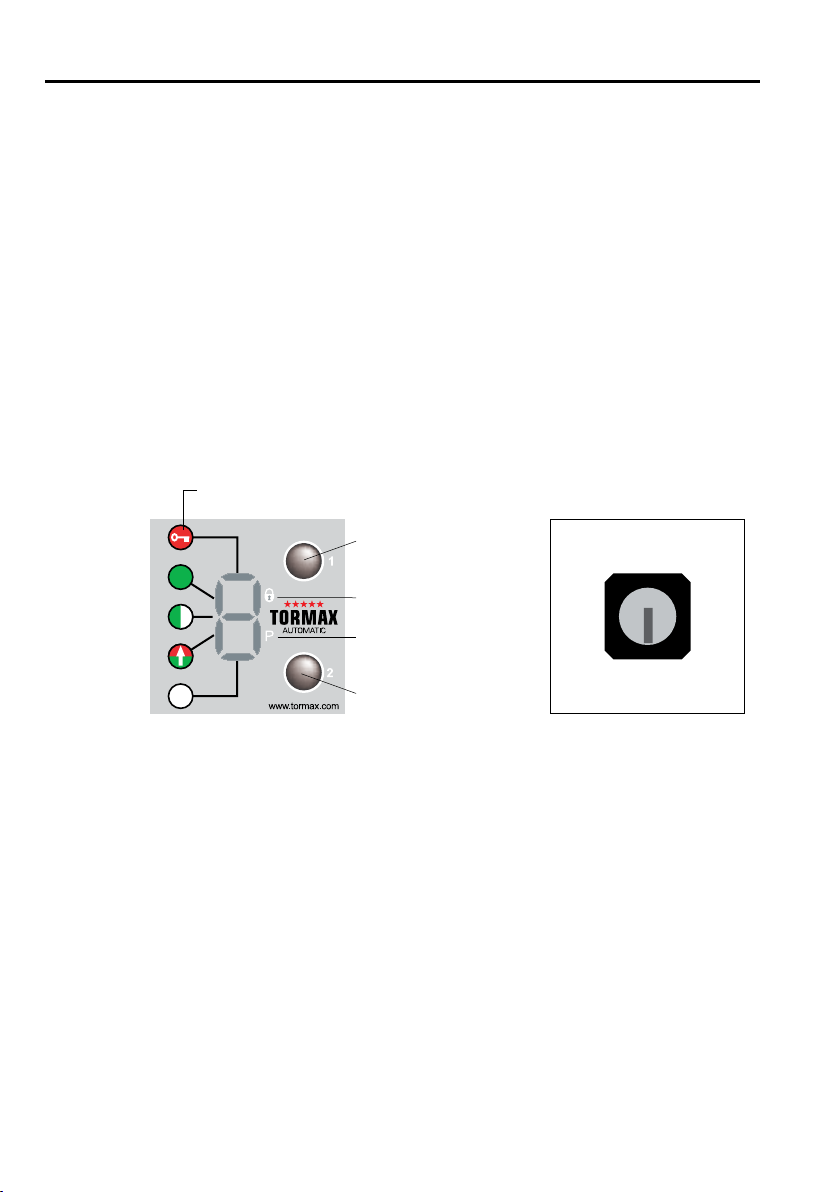
Instructions for Use TORMAX 1102, 1201 T-1661 e 19
7 Appendix
7.1 Fault Table
System Behaviour No. Cause Remedy/ Rectification
Note in the event of el-
evated motor load.
H17
H74
Drive is heavily loaded in the open
position by a soft stop or wind
load.
Remove the obstruction in the re-
gion of the open stop. Avoid wind
load.
The door stops when
opening.
H31 Electronic obstacle recognition
caused by persons, wind pressure
and ventilation when opening.
Remove the obstruction.
Avoid drafts.
Door reverses when clos-
ing.
H32 Electronic obstacle recognition
caused by persons, wind pressure
and ventilation when closing.
Remove the obstruction.
Avoid drafts.
The door stops repeat-
edly when opening.
The door stands still.
H33 Electronic obstacle recognition on
opening in the same position by
stationary obstacle.
Remove the obstruction.
The door stops repeat-
edly when closing.
The door stands still.
H34 Electronic obstacle recognition on
closing in the same position by sta-
tionary obstacle.
Remove the obstruction.
Search run notified. H62
H67
Search run of the door after a reset
or after power recovery.
Allow the search run to travel its full
course.
Door remains open or is in
operation again.
H71 System is in battery operation. Pause / ensure mains power supply
is connected.
Door remains closed. –
E11
E12
Operating mode for example OFF,
EXIT or P. The door is prevented
from moving by the lock.
Motor lock will not unlock
will not lock
E.g. select operating mode AUTO-
MATIC. Unlock the lock. Push the
door closed briefly.
Prevent wind load on the door leaf.
Remove obstruction in the closed
position area.
The door remains open. – Operating mode OPEN or the door
is obstructed in the open position.
E.g. select operating mode AUTO-
MATIC. Remove the obstruction.
The door remains closed.
The door moves slowly.
E31 The safety facility in the opening
direction is permanently active
(>1minute)ordefective.
Remove objects from within the
range of the sensor(s).
The door remains open
or closed. The door
moves slowly.
E32 The safety facility in the closing di-
rection is permanently active
(>1minute)ordefective.
Remove objects from within the
range of the sensor(s).
The door does not open
or does not close.
E33 The safety facility for the swing area
ispermanentlyactive(>1minute)or
defective.
Remove objects from within the
range of the sensor(s).
The door does not open
or does not close.
E34 The stop safety facility is perma-
nently active (>1 minute) or defec-
tive.
Remove objects from within the
range of the sensor(s).
The door opens slowly. E35
E37
The safety facility in the opening
direction is permanently active
(>1minute)ordefective.
Remove objects from the sensor
area.
The door closes slowly E36
E38
The safety facility in the closing di-
rection is permanently active
(>1minute)ordefective.
Remove objects from the sensor
area.
The door remains open. E41
E42
E43
Activatorinsideisactive>1min.
Activatoroutsideisactive>1min.
Keyswitchisactive>1min.
Get sensor adjusted by a skilled
person.
Reset the key switch.

20 Instructions for Use TORMAX 1102, 1201 T-1661 e
System Behaviour No. Cause Remedy/ Rectification
The door remains open E45 Emergency opening is active for
>1minute
Reset the command from the higher
ranking system.
The door remains closed E46 Emergency closing is active for
>1minute
Reset the command from the higher
ranking system.
The door remains closed E47 Blocking switch active for
>1minute
Reset the command from the higher
ranking system.
The door remains open E48 ”Beds“sensoractivefor>1minute. Resettheswitchfor“passagewith
beds”.
The door stands still E51 Anomaly in the travel distance.
Solid obstruction in the movement
area.
Remove firm obstacle in the travel-
ling range of the door.
Perform a software-reset.
The door stands still E61
E62
E63
Power supply is overloaded or volt-
age too low.
Get the power supply and connec-
tions checked by a skilled person.
The door stands still E64 Drive/control system is overheated. Wait for the automatic reset after
the door/control system has
cooled.
Protect from direct sunlight.
The door stands still E66 Motor or output stage defective. Wedge the door open in the open
position or disengage the linkage.
Switch off the power supply.
Arrange for the system to be re-
paired by a specialist.
The secondary door leaf
remains motionless.
E99 Fault on the secondary drive. Arrange for the system to be
checked by a specialist.
The door stands still. E..
E0..
E2..
Control system shut down for
safety reasons.
Perform a software-reset.
Arrange for the system to be re-
paired by a specialist.
Other manuals for 1102
2
This manual suits for next models
1
Table of contents
Other Tormax Door Opening System manuals
Popular Door Opening System manuals by other brands

Dormakaba
Dormakaba RTS88 installation instructions

FAAC
FAAC XPS quick start guide

Assa Abloy
Assa Abloy Norton 7200 Series Installation and instruction manual

Mowin
Mowin R60 instruction manual

Dormakaba
Dormakaba ED100 installation instructions

MANTION SMT
MANTION SMT WIBAT APPLIQUE installation instructions