Tormax TTXII User manual
Installation and Operating Manual
TTXII Swing Door Operator
T-1132 e 1.09
US801465
V1.4 and up

T-1132 e 2
First edition: 9.02 provisional for 0-Series
Update: 3.03, 8.04, 1.09
We print on environment-friendly paper bleached without chlorine.
The enterprises Landert Motoren AG and Landert GmbH are certified according to
ISO 9001.
Contents
1 Introduction 3
2 Safety 4
2.1 General Safety and Accident Prevention Regulations 4
2.2 Safeguarding Danger Points 5
2.3 Organizational Measures 6
3 Basic Functions 7 - 8
4 Installation
Outswing Surface Mount With 0” to 9 -7/8” Reveal 9
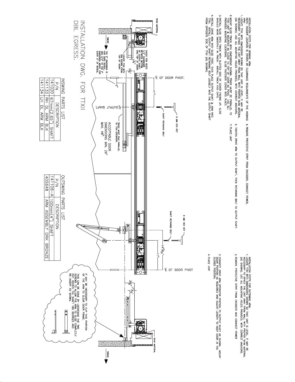
Double Egress with Surface Mount
5 Mechanical Adjustments
6 Electrical Connections and Wiring Diagrams 14 - 14g
7 Commissioning and Adjustments
7.1 Commissioning with “Teach-In General” 15
7.2 Programming Examples 16
7.3 Programming Table 17
7.4 Programming Functions
18 - 19
7.5
Simultaneous or Double Egress Programming 20 - 21
8 Trouble Shooting 22
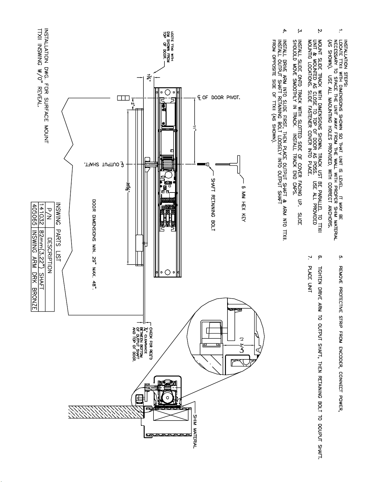
Inswing Surface Mount With 0” Reveal 10
12
Inswing Surface Mount With Deep Reveal 11
13
3
T-1132 e
Adressee
Area of Application
1 Introduction
These instructions are addressed to AAADM Certified installation and service
technicians.
This document is applicable to the Tormax TTXII swing door operator with SW 1.4
and up.
Non-compliance endangers the safety of the installation personnel, the system op-
erator or the user.
Warning of electrical voltage.
Passages with text on grey background must be absolutely observed for reliable
performance of the system! Neglect can cause material damages.
Explanation of Symbols

T-1132 e 4
2 Safety
2.1 General Safety and Accident Prevention
Regulations
Prior to installation or commissioning, read and follow this information that is being
described on this page—especially the following notes relating to safety—and adhere
to them at all times! Damage to the unit and personal injury may result if these instruc-
tions were not carefully followed.
Pay particular attention to the specially marked notes in this manual (for an explanation
of the symbols please refer to chapter 1)!
These products are Underwriters Laboratories, Inc. (UL) listed and cUL certified
for the Canadian marketplace, and therefore comply with the requirements of
the National Electrical Code (NEC) and the Canadian Electrical Code (CEC).
Installations intended to meet UL and cUL requirements must be followed as
described in the instruction provided herein. These are minimum standard re -
quirements. Where local codes exceed these requirements, they must be fol -
lowed as well.
Warnings of Dangerous Electrical Voltages or Current
Be sure the electrical power is disconnected and locked-out when working on the
operator unit.
Install the electrical cables and power only after the mechanical installation to the
unit is done.
Turn on the power to the operator unit only after all internal cables are connected.
Do not connect cables while the unit is powered.
Always use appropriate tools for installation and repair.
Prior to commissioning or performing any work on the door system, the operating in-
structions for the TORMAX operator and the following safety directions should be
studied with great care and must be observed!
General safety Instructions
Proper grounding methods has to employed to reduce magnitude of transient
over Voltage, To Simplify ground fault location,To improve system and equipment
fault protection,To reduce maintainence time and expense and greater safety
for personnel.
Installer should do permanent wiring as required by the local codes.
Preventing General Hazards and Possible Damage to This Equipment
Verify that the power selection switch is set to the correct voltage before start-up.
to the input power supply plug. It should not be routed through doorways, window
not be attached or otherwise secured to the building structure. It should not also be
concealed behind walls, etc.
parts of the operator, door, or system.
The power receptacle must be of the grounding-type. It is very important that the
unit will be properly grounded.

5
T-1132 e
TheTORMAXoperatorisdesignedaccordingtothecurrentstateoftechnologyas
well as the recognized safety-relevant regulations and is intended exclusively for the
deployment in conjunction with automatic interior and exterior doors (without wind
loads) used by people e.g. in hospitals, homes for the elderly, shopping centres, of¿ce
buildings and large-scale enterprises. The operator corresponds to protective class
IP 22. Without additional safety precautions, it may only be installed within, i.e. at the
inside,ofbuildings.
Anyotheruseoranyuseexceedingthisaimisdeterminedtobenotforitsintended
purposeandmayleadtopersonalinjurytotheuserorathirdparty.Furthermore,the
system or other material assets can be damaged. The manufacturer will not be respon-
sible for any damage resulting from this; the risk is carried entirely by the operator of
thedoorsystem.
The operating, service and maintenance conditions speci¿ed by the manufacturer are
to be maintained. The persons entrusted with the service and maintenance must be
acquainted with the matter and informed about any possible danger.
Toensureareliablefunctionofthedoorthemomentoffrictioncausedbye.g.bad
aligning of door leaves or wind charge may not exceed 5 Nm.
In addition to the operating instructions, the legal and other obligatory regulations for
accident prevention and environmental protection, in the respective country where the
door system is operated, shall be applicable. The special directives for automatic doors
(e.g. of the European committee for standardization CEN) must be adhered to.
Furthermore, the operational/national regulations apply.
Arbitrary changes to the system will exempt the manufacturer from any liability for
damages resulting from this.
2.2 Safeguarding Danger Points
General
Automaticdoorsystemsaretoconstructedinsuchamannerthatonopeningand
closing motions endangerments through jamming, shearing and drawing-in are
avoided or safeguarded against, for example through:
– Safety separations
– Limitation of the door-leaf forces
– Monitored safety facilities
–S
eparating protective facilities
DIN V 18650-2: 2003
ANSI Compliance - Always inspect your adjustments to be ANSI A156.10 or A156.19 compliant before
handing over to the enduser.
Maximum Door Leaf
Weights
Intended Purpose
0
50
100
200
220
320
400
36 42 48
Door leaf width
Door leaf weight
lb
In
T1132_40e

T-1132 e 6
2.3 Organizational Measures
The installation or service should be made by an AAADM Certified technician
in accordance with the latest ANSI A156.10 or A156.19 standard.
Contact Tormax for training classes conducted at our facility if you wish to
attend a factory training class.
Use the system only in a technically sound state. Eliminate faults immediately that
mayimpairsafety.
the drive lever, the linkage and the secondary closing edges of the hinges.
Use exclusively tools that are suitable for the respective work procedure. Pay atten-
tion to good condition of the tools.
Electricvoltage/current:Theoperatoristobedisconnectedfromelectricalmains
beforeanyworkisperformedonelectricalparts.
Install cabling only after the installation is complete.
Plug in the power plug only after all internal cables are connected.
Requirements for Installa -
tion or Service Technicians
Fundamental Safety Mea -
sures – Appropriate Behav -
iour

7
T-1132 e
3 Basic Functions
Motion Control – General
The door opens motor-driven in accordance with the stored speed pro¿le (see section
7.1) against the installed spring. If the motor torque decreases the door is braked down
by the spring. The door is held in the open position by a reduced motor torque. The
closing action is performed through spring force only. Thereby, the motor adjusts the
speed. At the completion of the closing motion, deceleration occurs with adjustable
homing in speed over an adjustable angle (see section 7.4.2). The motor is switched
off when the door is closed.
Functionalityoftheunit
OpensthedoorinoperatingmodeAUTOinaccordancewith“Teach-InGeneral”.
Opens the door in operating mode AUTO and in operating mode OFF in accordance
with “Teach-In General”, or with “Teach-In Key Switch” if this was performed after
“Teach-In General”.
Opens the door in AUTOMATIC mode according to the “Teach-In General ” instructions
when the door is manually pushed open to an adjustable angle. “Push-and-Go” can
be switched off.
Whentheopendoor(operatingmodeOPEN,duringhold-opentime,stepcontrol)is
movedmanuallyandconsiderably(16°)inclosingdirection,itwillcloseautomati-
cally.
This prevents the door from opening if closed, cancells the opening cycle or
If both the safety device in opening direction and the safety device in closing direction,
respond at the same time during a motion, the door stops in place. Through “Teach-In
General”, the safety sensor is disabled automatically – if necessary – over a predeter-
mined door swing range. If this function is not used, a jumper is inserted between
14–15.
Standard function:
Safety device in closing direction reactivates the door if the sensor becomes active.
If the door reaches the full closed position the input is inhibited and can be used manually
w/o activation. The input becomes active after another activation command is given.
Optional functions:
Safety device for the swing area
The input keeps a closed door closed and an open door open.
Safety Device Bodyguard
This function is only in use with the safety device “Bodyguard” of BEA.
The door remains open or closed. A commenced motion is completed.
Using this function automatically changes the settings of Feedback Door State to “door
opening or door open” data for the LO21 / LO21P lock out relay.
If these safety functions are not used, a jumper is inserted between 18–19.
Outputforactivetestingofthesafetydeviceinopeningdirectionandsafetydevicein
closing direction (i.e. BEA Superscan or Bircher Topscan).
An opening can only be initiated through the key switch. Switching to operating mode
OFFinterruptsanycurrenthold-opentime.
Activator (4 - 5)
Key Switch (7 - 8)
Safety device in closing
direction/safety device for
the swing area.
(18 - 19 NC)
Safety Device on
Pull / Swing side
(14 - 15 NC)
Test of safety devices
Operating Mode OFF
“Push / Pull”
“Push-and-Close”

T-1132 e 8
Feedback Door State
(door position)
Anopeningcanbeinitiatedbyanactivator,akeyswitchandalsoby“PushandGo”
depending upon con¿guration.
The door opens and stops in open position. It opens according to the settings of “Teach-
In General”.
Unlocks on each opening command. On completion of the opening time delay, the door
starts opening. When the door has moved somewhat in opening direction, the door
lockdropsoffagain.Thedoorlockisactivatedonlyinproximityofthe“doorclosed”
position.
The feedback “door closed” (or “door open” if recon¿gured)between11–12isonlyvalid
as long as mains supply is available. This message is established as soon as the
processor considers the driving function as complete. Connection for 24 VDC relay or
signal light. Transistor output short circuit proof in relation to internal supply voltage
24 VDC / 0.75 A.
Ifasecondopeningwidthhasbeencon¿gured(“Teach-Inkeyswitch”)thefeedback
“door open” is as follows:
Triggering of opening Feedback defined by
Activator “Teach-In General”
Key-switch “Teach-In key-switch”
“Push-and-Go” “Teach-In General”
Manual operation the smaller of both opening widths
The control provides .75 amps total to the sensors and the lock output. If the control
is over loaded the led point may start to flicker, go dim or completley turn off. If this
occurs install an aux power supply to power up your accessories.
Ifthedoorhitsa¿rm obstacle during opening, the motor driven opening procedure is
terminated immediately. If the door hits an obstacle during closing, it opens again waits
forthesafetytimetoelapseandtriestocloseagain.Thenextopeningcommandopens
thedooragainasusual.Ifreversingisswitchedoff,thedoorstaysontheobstacle
whenclosed.Onopeningafter60seconds,thepoweredopeningprocedurestops.
The door opens when an impulse is received (key-switch, activator or “Push-and-Go”),
remainsinthevalidopenpositionduringthevalidhold-opentime,andclosesthere-
after again.
The door opens when an impulse is received (from the key switch, activator or “Push-
and-Go”) and remains in the open position. The door closes immediately after the next
impulse or “Push-and-Close”. The motional sequence depends on the settings of the
respective “Teach-In”.
The motorisswitchedoffimmediatelywhenthedoorisblocked.
Motor and transformer contain thermal relays that interrupt the current supply to the
control system at 230 °F. The system operates as during a power failure until the
temperature drops to 185 °F.
Thedoorcanbemanuallyopenedifthedoorlockcanbeunlockedwiththedoorhan-
dle. The door closes through spring force. The motor, which is controlled short-circuited,
controls the closing action with constant braking power. After return of power, the
system is immediately ready for use again.
Power Supply 24 VDC
Reversing Motion
(Reverse on Obstruction)
Time Control
Step Control
Internal Protective Devices
Power Failure
Operating Mode OPEN
Door Lock
Operating Mode AUTO

4 Installation
3/8”
14 - 15/16”
)ROTAREPOII-XTTEHTGNINOISIMMOC(7NOITCESEESDNAOTUAOTNI
9
TINUECALP
,
T
F
A
HSTUPTUOLLATS
NIGE
D
02
.XORPPADETATOR
SAHROTOMECNO.NEPODLOHOTNI
TFAHSTUPTUOEUQROTDNAREH
TOHCAE
HTIW
LELLRAPGNINNURB&ASECAFRUSHTIW
.SBL-.TF03OT
)ROTAREP
OII-X
TTEHTGNINOISIMMOC(
7NOITCESEESDNAO
T
UAO
TN
I
10
OTNITINUECALP
GNIDAOLERPROFNEPODLOH

)ROTAREPOII-XTT
EHTGNINOISIMMOC(7NOITCESEESDNAOTUAOTNI
11
OTNITINU
ECALP
GNIDAOLERPROFNEPODLOH
)ROT
AREPOII-
XTTEHTGNINO
ISIMMOC(7NOITCESEESDNAOTUAOTNI
)ROTAREPOII-XTTEHTGN
INOISIMMOC(7NO
ITCESEES
DNAOTUAOTNI
12
GNIDAOL
E
R
P
ROFNEPODL
OH
OTNITINUE
CALP
,PLACE UNIT
INTO HOLD OPEN. ONCE MOTOR HAS ROTATED APPROX . 20 DEG, INSTALL
OUTPUT SHAFT AS SHOWN WITH SURFACES A & B RUNNING PARALLEL
WITH EACH OTHER AND TORQUE OUTPUT SHAFT TO 30 FT. -LBS.
T-1132 e 13
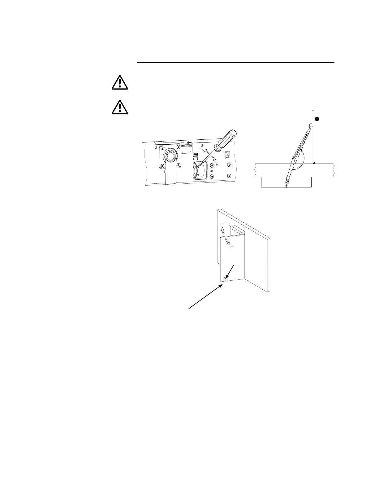
5 Mechanical Adjustments
An external door stop may be installed as shown but you must leave a 3/8” space
between the door and any physical stop.
The door should only be opened so far that the standard linkage cannot tip over and
the sliding lever does not leave the rail.
90°
!
External door stop.

14
T-1132 e
6 Electrical Connections
Before beginning the work described here check that the mains supply is switched
off.
If possible, route the mains connection along the side of the power supply to the op-
erator.
The connecting cables must be of the type “PVC cable H05VV-F” or “rubber hose
cable H05RR-F”.
Round the edges and remove burrs from all conduits used for the mains connection.
Remove mains supply cover (1).
Connect the mains cable to terminal (11)
in accordance with gure.
Route the mains cable either through the
prepared holes of the side cover or through
the slots in the mounting plate.
Use only cable bushings made from syn-
thetic materials. Metallic bushings are to
be earthed.
Check correct adjustment of the voltage
selector (12) and reinstall the mains supply
cover (1).
Mains Connection
10AT
L1 3mm
N
230/115V~
50/60 Hz
T1132/1
L1
N
12
11
1
1
2
3
4
5
6
7
8
9
10
11
12
13
14
15
16
17
18
19
20
1
To Reduce the risk of electric shock, it is critical that all wiring ........
1) Be properly Grounded
2) Be permanently Fastened
3) Satisfy local code requirements.

SW D61-070809 / V1.4 Installation On Site SWINGDOOR Smart Drive 1101 T-1132 e 14 a
Terminal Connections
Legend:
*programmable
A57.0.xamlatot,)CDV42…12(CDV42V42+
IN Input (contact load 24 VDC / 4 mA)
edoidevitcetorpdetargetni)A57,0/CDV42daol.xam(NPNtuptuOTUO
** Applying an impulse on operating mode OFF (min 0.6 s) interrupts the
current hold-open time.
1 2 3 4 5 6 7 8 9 10 11 12
IN
GND
IN
GND
IN
+24 V
GND
IN
OUT
+24 V
OUT
+24 V
Activator
Status indication
door closed/*open
** OFF
AUTO
OPEN
Key switch
Door lock 24 VDC
locked currentless
* unlocked currentless
–
+
No protective
circuit necessary
13 14 15 16 17 18 19 20
–
+
GND
IN
OUT
24 V
GND
IN
OUT
24 V
+
+
–
+
Safety devices without
monitoring
Safety device
in opening
direction
Safety device in
closing direction/
*Swing area

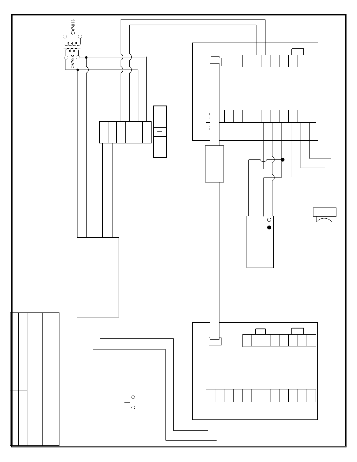
Title:
TTXII WITH LARCO 433 WIRELESS
RECEIVER AND TRANSMITTER
Dwg.
by:
Date:
DWG NO:
OFF/AUTO/HOLD OPEN
Red
White
Blue
Beto Rendon
4-3-06
22d
Note:
Please see programming matrix on page 25 for setup.
LARCO ULTRA SMALL
433 REC
LARCO 433
TRANSMITTER
BLACK
BROWN/WHITE
RED
ORANGE
IN
GND
IN
GND
IN
IN
GND
1
2
3
4
5
6
7
8
9
10
11
12
+24v
OUT
+24v
OUT
+24v
GND
GND
IN
OUT
+24V
IN
OUT
+24V
13
14
15
16
17
18
19
20
TTX II
14 b

Title:
Dwg.
by:
Date:
DWG NO:
OFF/AUTO/HOLD OPEN
Red
White
Blue
Beto Rendon
11/14/06
22e
Note:
1) Please see programming matrix on page 25 for proper programming and setup for operators (Safety Device Bodyguard).
2) Bodyguard relay must be changed to 2 NC.
Bodyguard III
Red
Black
White
Green
Brown
Blue
LO21
Orange
Brown
Red/White
White
Red
Black
ACTIVATION
TTX II WITH BODYGUARD AND LO21
IN
GND
IN
GND
IN
IN
GND
1
2
3
4
5
6
7
8
9
10
11
12
+24v
OUT
+24v
OUT
+24v
GND
GND
IN
OUT
+24V
IN
OUT
+24V
13
14
15
16
17
18
19
20
TTX II
14 C
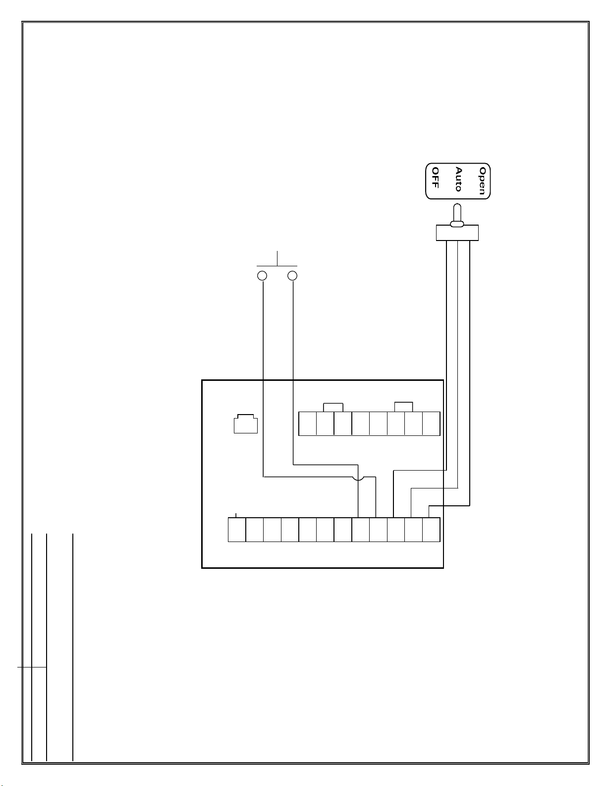
Title:
TTXII Btm Load
Dwg.
by:
Beto Rendon
Date:
2/15/08
DWG NO:
Green
White
Red
ACTIVATION
IN
GND
IN
GND
IN
IN
GND
1
2
3
4
5
6
7
8
9
10
11
12
+24v
OUT
+24v
OUT
+24v
GND
GND
IN
OUT
+24V
IN
OUT
+24V
13
14
15
16
17
18
19
20
TTX II
14 d
22 L

Title:
TTXII PAIR WITH LARCO 433 WIRELESS
RECEIVER AND TRANSMITTER
Dwg.
by:
Beto Rendon
Date:
2-12-09
DWG NO:
22N
OFF/AUTO/HOLD OPEN
Red
White
Blue
Note:
See programming matrix on page 25 and programming procedure on page 30.
LARCO ULTRA SMALL
433 REC
BLACK
BROWN/WHITE
RED
ORANGE
Master
LARCO 433
TRANSMITTER
IN
GND
IN
GND
IN
IN
GND
1
2
3
4
5
6
7
8
9
10
11
12
+24v
OUT
+24v
OUT
+24v
GND
GND
IN
OUT
+24V
IN
OUT
+24V
13
14
15
16
17
18
19
20
TTX II
IN
GND
IN
GND
IN
IN
GND
1
2
3
4
5
6
7
8
9
10
11
12
+24v
OUT
+24v
OUT
+24v
GND
GND
IN
OUT
+24V
IN
OUT
+24V
13
14
15
16
17
18
19
20
TTX II
406079
Primary Secondary
14 e
Title:
TTXII PAIR WITH LO21, BODYGUARD AND
433 WIRELESS RECEIVER.
Dwg.
by:
Beto Rendon
Date:
2-13-09
DWG NO:
22O
Note:
See programming matrix on page 25 and programming procedure on page 30.
Set Bodyguard to relay 2 - NC.
LARCO 433
TRANSMITTER
LO21
Orange
Brown
Red/White
White
Red
Black
Black
White
Green
Blue
Red
Brown
Bodyguard II
I
OFF/AUTO/HOLD OPEN
Red
White
Blue
LARCO ULTRA SMALL
433 REC
BLACK
BROWN/WHITE
RED
ORANGE
Primary Secondary
IN
GND
IN
GND
IN
IN
GND
1
2
3
4
5
6
7
8
9
10
11
12
+24v
OUT
+24v
OUT
+24v
GND
GND
IN
OUT
+24V
IN
OUT
+24V
13
14
15
16
17
18
19
20
TTX II
IN
GND
IN
GND
IN
IN
GND
1
2
3
4
5
6
7
8
9
10
11
12
+24v
OUT
+24v
OUT
+24v
GND
GND
IN
OUT
+24V
IN
OUT
+24V
13
14
15
16
17
18
19
20
TTX II
406079
14 f
Table of contents
Other Tormax Door Opening System manuals


Popular Door Opening System manuals by other brands

Simons Voss Technologies
Simons Voss Technologies SmartHandle Series manual

Dormakaba
Dormakaba CLPKT90 installation instructions

Frisco
Frisco Eclipse 73 Series installation guide

MPC
MPC ATD ACTUATOR 50 ATD-313186 Operating and OPERATING AND INSTALLATION Manual

ADL
ADL LIGHT Assembling instructions

Record
Record DFA 127 user manual

Dormakaba
Dormakaba HSW EASY SAFE installation instructions

Automatic Technology
Automatic Technology Syncro ATS-3 Quick operation guide

Bohle
Bohle BO 5215430H instruction manual

DDS
DDS 2300CA Series Operation and maintenance manual

Genie
Genie GCL OPGSX Series installation manual

Cal-Royal
Cal-Royal CR801 Series installation instructions


