tornos Deco 7a User manual
IT −DECO 7a/10a
TORNOS SA −CH−2740 MOUTIER −http://www.tornos.ch Printed in Switzerland Copyright (c)1999−2004
MOUNTING Y1Y2 LINEAR GUIDES
TT5497 en
∆Warning ! Failure to comply with the safety regulations may cause serious accidents.

These instructions are based on the information available at the moment of their publication. Although
the very best has been done to make them as comprehensive and precise as possible the instructions
do not purport either to cover all details of the hardware and software or to anticipate every con-
tingency.
TORNOS S.A. neither give any guarantee nor accept any liability for the exactitude and the suffi-
ciency of the information contained in this document.
The contents of the instructions remain the property of TORNOS S.A. who reserve the right to modify,
complete or correct them at any time.
The original language of the instructions to be referred to is French. The hazards of misinterpreting
the instructions can be considerably reduced by following the training courses organized and offered
by TORNOS S.A.
The CE-marking indicates conformity with the European standards
of safety, health, environment and protection.
TORNOS S.A.
Rue Industrielle 1 1 1
CH−2740 MOUTIER / SUISSE
Tél. 032 / 494 44 44
Fax 032 / 494 49 03
TORNOS TECHNOLOGIES
IBERICA
Pol. Ind. El Congost
Avda. St Julia, 206 Nave 8
E−08400 GRANOLLERS
Tel. (34) 93 846 59 43
Fax (34) 93 849 66 00
TORNOS−TECHNOLOGIES
DEUTSCHLAND
Karlsruher Str. 38
D−75179 PFORZHEIM
Tel. 07231/ 910 70
Fax 07231/ 910 750
TORNOS TECHNOLOGIES
ITALIA SRL Via Einstein, 24
I−20090 ASSAGO / MI
Tel. 02 45 77 17 01
Fax 02 45 70 16 48
TORNOS TECHNOLOGIES
FRANCE
Boîte postale 330
ST−PIERRE EN FAUCIGNY
F74807 LA ROCHE
S / FORON CEDEX
Tél. 04 50 038 333
Fax 04 50 038 907
TORNOS TECHNOLOGIES
US CORPORATION
70 Pocono Road PO. Box 325
BROOKFIELD CT 06804 / USA
Tel. (203) 775−4319
Fax (203) 775−4281
TORNOS TECHNOLOGIES UK Ltd Tornos House
Whitwick Business Park Coalville
Leicestershire
LE67 4JQ
Tel. 01530 513100
Fax 01 530 814212

IT MONTING −DECO 7a/10a
Chap. / 3TT5497 en −12/04
Differentiation of degrees of risk
These instructions indicate a number of safety measure symbols which appear also on the machine
and are intended to protect the user, his/her effects and the environment from injuries and damage
as applicable.
Below, you will find the safety symbols, their headings and definitions. Please, read these first before
you continue.
∆Danger !
indicates a direct danger of death or serious injury.
∆Warning !
indicates an object or action which may cause death or serious injury.
∆Caution !
indicates an object or action which may cause injury or serious damage.
∆Attention !
indicates incorrect actions or such that may cause damage.
⊗Prohibition !
indicates an action or operation prohibited because of evident or alleged hazards.
⇒Info :
Gives information or comment related to safety.
⇒Note :
Gives information unrelated to safety
Important Safety Indications
∆Warning !
Read the instruction before operating the machine.
Should the user disregard the instructions of this manual, TORNOS SA declines any liability
whatsoever.
∆Attention !
Certain maintenance works are absolutely necessary to ensure good operation of the
machine. They are given in the MAINTENANCE SCHEDULE on the machine
(or see Instructions: OPERATION-MAINTENANCE).
∆Caution!
TORNOS SA disclaims all responsibility for any modifications carried out by the customer to
the machine, and to its related equipment and software, without agreement ratified by
TORNOS SA.

IT MONTING −DECO 7a/10a
Chap. / 4 TT5497 en −12/04
∆Caution !
Make sure the axis belts are changed by a professional who has attended a TORNOS mainte-
nance training !
Before you change the belt of a vertical axis, lock the carriage to keep it from sliding down in
free fall !
∆Warning !
First thing to do before any maintenance work :
−Turn off and lock Main Switch to stop the machine.
−Wear gloves to avoid injury from metal chips or sheeting.
−Do not touch the motor enclosure when it is still hot !
∆Caution !
Change the belt when its condition has visibly deteriorated :
−A notch is cracked.
−A notch is broken.
−The protective strip is damaged.
−The steel cords appear at the side.
∆Caution!
TORNOS SA disclaims all responsibility for any modifications carried out by the customer to
the machine, and to its related equipment and software, without agreement ratified by
TORNOS SA.

IT MONTING −DECO 7a/10a
Chap. / 1TT5497 en −12/04
TECHNICAL INSTRUCTION FOR MOUNTING Y1Y2 LINEAR GUIDES ON
DECO 7/10
GENERAL DATA
Group Identification : 305015 compound slide for frontwork gang – guides DN 15 lg 236
ident. 241621
305016 compound slide for backwork gang −guides DN 15 lg 236
ident. 241621
Tools: 1 torque wrench 05 à 20 Nm
1 hex socket long. 130mm
(for torque wrench)
1 comparator (0.002) with magnetized base.
⇒RECOMMENDATION : When replacing guides, it is recommended to change the holder
eccentrics (561096 Pos 0190).
What to do ? Notes
PREPARATION :
Unpack the linear guides ; remove the
O−Rings located on the greasing plates of
each ball carriage and set them aside to
prevent misplacing them.
Using a ruler, make sure that the greasing
plate height is not greater than the support
surface of the ball carriages.
Clean off all the protective oil residue from the
support surfaces of the guides and carriages.
Hone the base of the guides (rails).
MOUNTING (ASSEMBLY):
Place the linear guides DN 15 ( Ident. 241621
Pos. 0280) on the ”x” frontwork gang carriage
(561134 Pos. 090) or the ”x” backwork gang
carriage (561142 Pos. 050)... ...to obtain the reference surfaces of the
guides and carriages opposite the
eccentrics.
Push the carriages to one end of the guides in
order to insert the first 4 fastening screws for
each guide M4x14 (020162 Pos. 0400/0390)
and tighten slightly.
Move the carriages to the other end and insert
the last 4 screws M4x14 and tighten slightly.
Torque the eccentrics (561096 Pos. 0190) by
alternating from the center to left / right to
6 Nm.
Torque to 6Nm

IT MONTING −DECO 7a/10a
Chap. / 2 TT5497 en −12/04
What to do ? Notes
Torque the fastening screws M4x14 of the
guides (rails) following the same procedure as
for the eccentrics to 6 Nm
Torque 6Nm
Insert the 2−piece caps delivered as a guide
accessory into the fastening screw holes of
the guides (Insert the drilled plastic washer
first and then the teflon cap and using a flat
tool press into the hole. Check that the
carriages move freely without binding).
Reinstall the O−Rings in their recess in the
greasing plates at each end of the ball
carriages. Grease the O−Rings to hold them
in their recess.
MOUNTING THE FRONTWORK AND BACKWORK GANGS ON A CARRIAGE:
Place the frontwork gang or backwork gang,
respectively, 561140 / 561143 Pos. 030, on
the linear guide carriages.
Insert the 16 screws M5x16 (Ident. 020175
Pos. 0370/0360) and tighten slightly by
alternating left / right.
( By X)
Torque the eccentrics (561096) on the
carriages to 6 Nm starting from the outer
eccentrics to the inner eccentrics.
Fully torque the fastening screws of the gang
on the ball carriages to 11 Nm by alternating
left / left.
(By X).
TEST / ALIGNMENT
With the compound slide for front/backwork
gang assembly laid flat on the bench, insert
only for this test in the 6 mm dia. bores the
frontwork gang / backwork gang, respectively
(561140 / 561143 Pos 030), 2 cylindric cotter
pins h6, or equivalent.
Using a comparator with its magnetic base
placed on the ”x” gang carriage, gauge the
side of the two cotter pins. An error of 0.006
mm is allowable. If the error should be greater
than this reference value, completely repeat
the torquing operation. To solve the problem, it
is possible to touchup the support surface of
the ball carriages on the front/backwork
gangs, respectively (561140 / 561143 pos.
030), by polishing it.

IT MONTING −DECO 7a/10a
Chap. / 3TT5497 en −12/04
What to do ? Notes
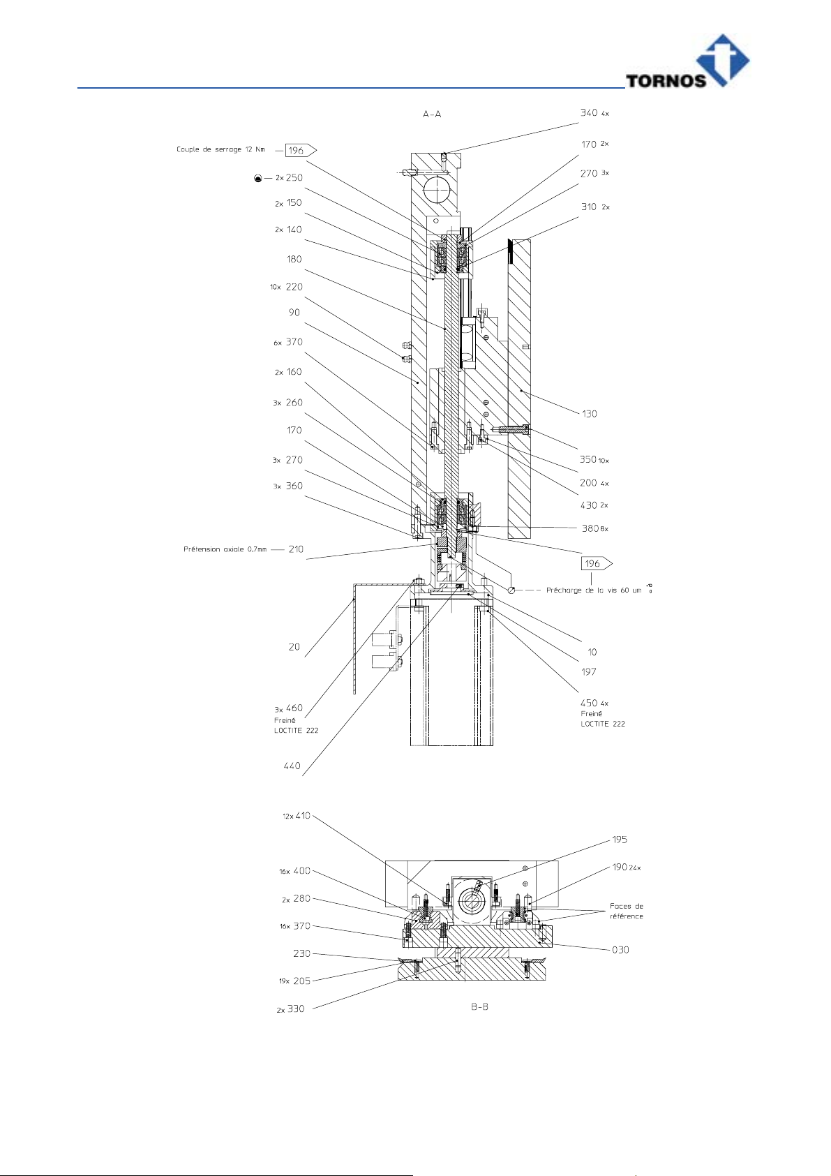
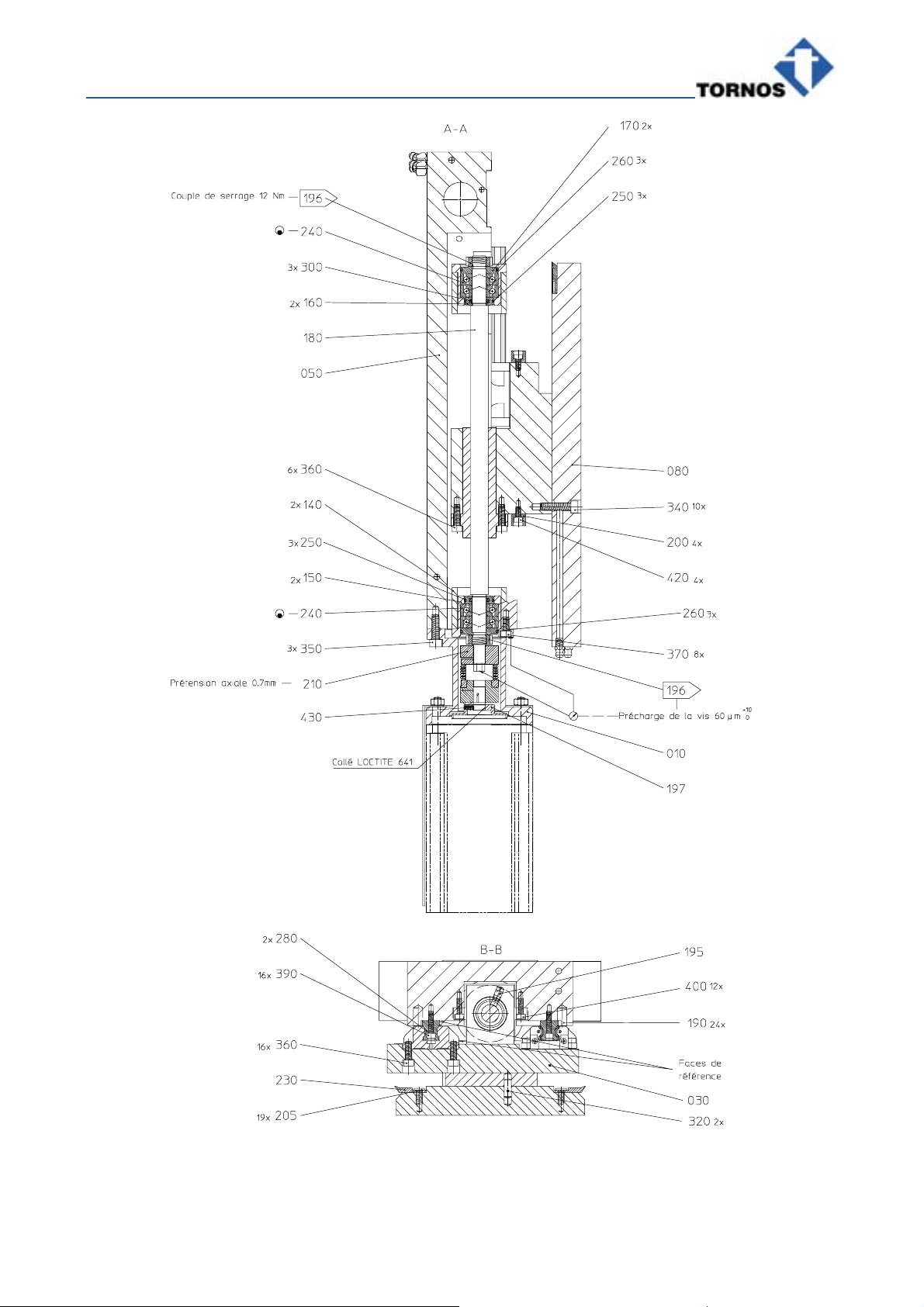
INSTALLING THE BALLSCREW :
Insert the ballscrew (561102 Pos. 0180) in its
recess on the gang carriage (Pos 030)... ... by aligning the gang carriage / ballscrew
greasing holes.
Secure it with 6 screws M5x16 (Pos.
0370/0360) and torque to 11 Nm after
adjusting the clearance in the middle.
Mount the 2 roller bearings (561131 Pos.
0140) and the 2 rings (561119 Pos. 0150) on
the ends of the ballscrew...
...(without fully tightening the screws M4x12
(020161 Pos. 0410/ 0400)).
Move the Y front/backwork gang carriage
(561140 / 561143 Pos. 030) to the Up position
and, using a pin wrench, torque the upper nut
of the ballscrew (561443 Pos. 0196)
to 12 Nm.
Insert the 2nd nut of the ballscrew (561443
Pos. 0196) without fully tightening so that the
first thread of the ballscrew is visible.
Using the ballscrew, make one complete
down−to−up travel of the Y front/backwork
gang carriage to allow mounting the elements.
Move the Y front/backwork gang carriage to
the middle position and torque the 6 screws
M4x12 (020161 Pos. 0410/0400) of the 1st
bearing to 6 Nm.
Move the Y front/backwork gang carriage to
the Down position. Attention : Make sure that
the ball carriages remain completely on their
linear guides. Push the 2nd bearing (561131
Pos. 140) toward the inside of the assembly to
completely realign the clearance and torque to
6 Nm.
Once again move the Y front/backwork gang
carriage to the Up position (“end of travel”)
and torque the 4 screws M5x10 (020173 Pos.
0380 / 0370) securing the ring 561119 (Pos.
150) to 11 Nm.
Move the Y front/backwork gang carriage to
the opposite “end of travel” and torque the 4
screws M5x10 securing the second ring to 11
Nm (idem above).

IT MONTING −DECO 7a/10a
Chap. / 4 TT5497 en −12/04
What to do ? Notes
TEST:
Position the comparator with the feeler gauge
against the ballscrew surface.
Screw/unscrew once or twice the nut of the
ballscrew (561443 Pos. 0196) so that the
roller bearings are correctly installed in the
ring.
Tighten the nut, adjust the comparator to “0”
and preload the ballscrew to 0.06 mm.
Check how the system operates as it travels
from “end to end”.
Check on the machined true diameter at the
end of the ballscrew its variation in roundness.
A maximum tolerance of 0.005 mm is allowa-
ble. If necessary, readjust.
IT MONTING −DECO 7a/10a
Chap. / 5TT5497 en −12/04
305015f1
IT MONTING −DECO 7a/10a
Chap. / 6 TT5497 en −12/04
305016f1
This manual suits for next models
1
Table of contents
Other tornos Industrial Equipment manuals


