tornos DECO 20 Headstock Revision Manual
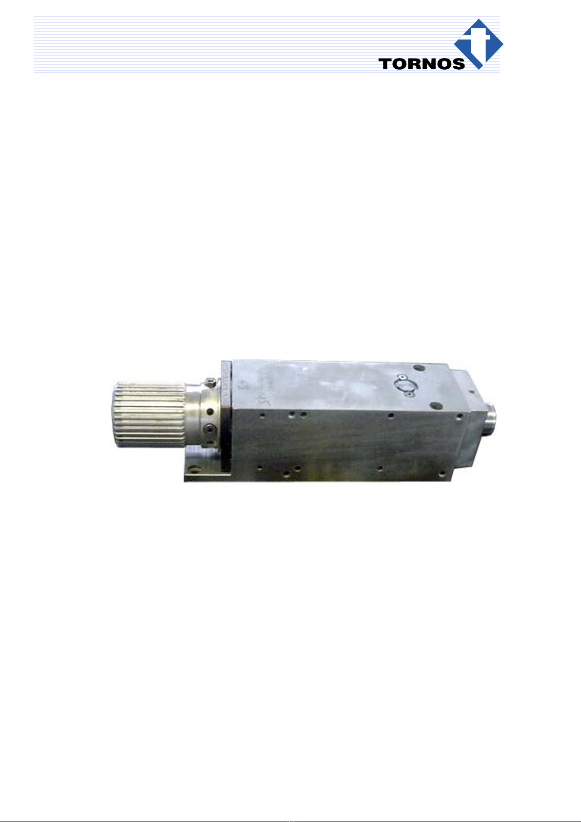
DECO Internal RP
TORNOS SA − CH−2740 MOUTIER − http://www.tornos.ch Imprimé en Suisse Copyright (c)1999−2004
DECO 20 Headstock Revision Ref. 306004
DESCRIPTION − PROCEDURES en TT5503

TT5503− DECO 13a Headstock Revision − Ref. 307001
Chap. / 2 TT5503 en − 12/04
Differentiationof degrees of risk
These instructions indicate a number of safety measure symbols which appear also on the machine and are
intended to protect the user, his/her effects and the environment from injuries and damage as applicable.
Below, you will find the safety symbols, their headings and definitions. Please, read these first before you con-
tinue.
∆Danger !
indicates a direct danger of death or serious injury.
∆Warning !
indicates an object or action which may cause death or serious injury.
∆Caution !
indicates an object or action which may cause injury or serious damage.
∆Attention !
indicates incorrect actions or such that may cause damage.
⊗Prohibition !
indicates an action or operation prohibited because of evident or alleged hazards.
⇒Info :
Gives information or comment related to safety.
⇒Note :
Gives information unrelated to safety
Important Safety Indications
∆Warning !
Read the instruction before operating the machine.
Should the user disregard the instructions of this manual, TORNOS SA declines any liability what-
soever.
∆Attention !
Certain maintenance works are absolutely necessary to ensure good operation of the machine. They
are given in the MAINTENANCE SCHEDULE on the machine
(or see Instructions: OPERATION-MAINTENANCE).
∆Caution!
TORNOS SA disclaims all responsibility for any modifications carried out by the customer to the
machine, and to its related equipment and software, without agreement ratified by
TORNOS SA.

TT5503− DECO 13a Headstock Revision − Ref. 307001
3TT5503 en − 12/04
TABLE OF CONTENTS
1. EQUIPMENT 5. . . . . . . . . . . . . . . . . . . . . . . . . . . . . . . . . . . . . . . . . . . . . . . . . . . . . . .
2. DISMOUNTING THE HEADSTOCK 5. . . . . . . . . . . . . . . . . . . . . . . . . . . . . . . . . . .
3. CHECKING THE PARTS 7. . . . . . . . . . . . . . . . . . . . . . . . . . . . . . . . . . . . . . . . . . . . .
4. MOUNTING 8. . . . . . . . . . . . . . . . . . . . . . . . . . . . . . . . . . . . . . . . . . . . . . . . . . . . . . . .
4.1 PREPARING THE PARTS 8. . . . . . . . . . . . . . . . . . . . . . . . . . . . . . . . . . . . . . . . . . . . . . . . . . . . . . . .
4.2 MOUNTING THE HEADSTOCK 9. . . . . . . . . . . . . . . . . . . . . . . . . . . . . . . . . . . . . . . . . . . . . . . . . . .
5. CHECKING THE HEADSTOCK 12. . . . . . . . . . . . . . . . . . . . . . . . . . . . . . . . . . . . . . .
6. BREAKING IN THE HEADSTOCK 12. . . . . . . . . . . . . . . . . . . . . . . . . . . . . . . . . . . .
7. ASSEMBLY DRAWINGS 13. . . . . . . . . . . . . . . . . . . . . . . . . . . . . . . . . . . . . . . . . . . . .
8. APPENDIX − DECO 13A BREAK−IN SHEET 15. . . . . . . . . . . . . . . . . . . . . . . . .

TT5503− DECO 13a Headstock Revision − Ref. 307001
4 TT5503 en − 12/04
>>>

TT5503− DECO 13a Headstock Revision − Ref. 307001
Chap. 2. / 5TT5503 en − 12/04
1. EQUIPMENT
Assembly drawing ref. 307001
Assembly drawing ref. 307024
Press travel ~600mm
Grease Mobile 28
Kubler NBU15
Molykote DX
Headstock filling oil ISO GV 220
Screw locking product Loctite 243
2. DISMOUNTING THE HEADSTOCK
Actions Notes
After dismounting the headstock from the machine :
1. Remove the thrust tube.
2. Remove the nipple screw (40).
⇒Note :
Refer to the assembly drawings, ref. 307001
and 307024.
3. Remove the plugs (60), the tubings (70) and the
endpiece (140).
Then remove the gaskets.
4. Loosen the 8 front screws (200).
5. Remove the flange (80).
6. Push the flange to remove the thrust ring (320).
7. Remove the screws (360).
8. Tighten the screws (30) to release the spring
(330).
9. Using the press, remove the spindle.

TT5503− DECO 13a Headstock Revision − Ref. 307001
Chap. 2. / 6 TT5503 en − 12/04
Actions Notes
10.Then remove :
the floating solenoid valve (100),
the spacer (90). 90
100
11. Remove the rear roller bearing (120).
12.Remove the roller bearings from the case (120)
through the passage holes.
13.Dismount the sleeve by removing the 4x screws
(220).

TT5503− DECO 13a Headstock Revision − Ref. 307001
Chap. 3. / 7TT5503 en − 12/04
3. CHECKING THE PARTS
∆Caution !
CLEAN THE PARTS TO CHECK FOR CONDITION.
Actions Notes
1. Check if the front side and/or the rear side of the
pushrod are worn.
2. Change all the damaged parts with contact rust or
wear.
3. Change the roller bearings.
4. Change the gaskets.

TT5503− DECO 13a Headstock Revision − Ref. 307001
Chap. 4.1 / 8 TT5503 en − 12/04
4. MOUNTING
∆Caution !
To assure the equipment, the thrust tube must be mounted at Tornos. A balancing machine is
required for the mounting.
Check the parts before mounting to make sure they are not defective.
4.1 PREPARING THE PARTS
Actions Notes
1. Lightly grease the gaskets and the mechanical
surfaces in contact.
⇒Note :
Use the grease Kubler NBU15 or Mobil 28.

TT5503− DECO 13a Headstock Revision − Ref. 307001
Chap. 4.2 / 9TT5503 en − 12/04
4.2 MOUNTING THE HEADSTOCK
1. Mount the rear roller bearings (310) in the case
(120)
Roller bearing : 71909 P4.
⇒Note :
Note and apply mark Aon the roller bearings.
310
120
A
2. Mount the front roller bearings (300) in the heads-
tock body. 300
3. Position the sleeve hole (20) with the headstock
body.
20

TT5503− DECO 13a Headstock Revision − Ref. 307001
Chap. 4.2 / 10 TT5503 en − 12/04
Actions Notes
4. Tighten and apply some locking product to the 4
screws (220). ⇒Note :
Use the locking product Loctite 222
5. Grease and insert the clamping screws (30).
6. Tighten the screws with brass wire (360 / 370).
7. Insert the compression springs (330).
⇒Note :
Use the grease Mobil 28.
8. Mount the case, making sure to install the nar-
rowest part on the right side and then tighten in
place with the screws (50).
∆Caution !
Make sure the case does not extend over the
side, which is possible.
9. Mount the gasket (270) inside the spacer.
270
10. Mount the solenoid valves.
11. Mount the headstock body on the spindle.

TT5503− DECO 13a Headstock Revision − Ref. 307001
Chap. 4.2 / 11TT5503 en − 12/04
12.Mount the baffle plate (110).
13.Insert the flange (80).
14.Using the press, push the flange and insert the
thrust ring (320).
⇒Note :
Align the ring and the flange with the case hole.
15.Tighten and apply some locking product to lock
the 8 screws (200).
⇒Note :
Use the locking product Loctite 243
Always alternately tighten the screws diagonally.
16.Loosen the adjusting screws (30) and then tighten
1/2 turn and reloosen 1/4 turn.
17.Tighten the screws (360) with brass wire.
18.Mount the tubings (140) and the covers with
gaskets (260 / 280 / 340).
19.Insert the plugs (60).
20.Mount the 4 screws (210).
⇒Note :
Position the tubings and plugs according to the
spindle or pickoff spindle on the machine.
21.Mount the plugs, the gaskets and the tubings
opposite.
80
320
200

TT5503− DECO 13a Headstock Revision − Ref. 307001
Chap. 6. / 12 TT5503 en − 12/04
5. CHECKING THE HEADSTOCK
Actions Notes
1. Check concentricity by positioning a comparator
inside the spindle, as well as on the spindle front
side.
⇒Note :
Max. 0.002 mm on the front side.
Max. 0.002 mm inside the spindle.
If necessary, use the 8 adjusting screws A to
adjust the concentricity of the spindle.
2. Insert the collet lightly greased and also check the
concentricity.
⇒Note :
Max. 0.005 mm.
∆Caution !
If the spindle is not within tolerance, dis-
mount the spindle again, check and remount
the assembly.
A
6. BREAKING IN THE HEADSTOCK
Actions Notes
1. See the break−in procedure sheet ⇒Note :
Make a photocopy of the original break−in
sheet.

TT5503− DECO 13a Headstock Revision − Ref. 307001
Chap. 7. / 13TT5503 en − 12/04
7. ASSEMBLY DRAWINGS
307001f1

TT5503− DECO 13a Headstock Revision − Ref. 307001
Chap. 7. / 14 TT5503 en − 12/04
>>>

TT5503− DECO 13a Headstock Revision − Ref. 307001
Chap. 8. / 15TT5503 en − 12/04
8. APPENDIX − DECO 13A BREAK−IN SHEET
1st level 2nd level 3rd level 4th level End of break−in period
Speed 2000 rpm 6000 rpm 12 000 rpm
Time 30 min 15 min 183 min Total
228 mm
Amperage
Front
Bearing
Initial 30
Bearing
Temperature 60
Temperature
90
120
Rear
Bearing
Initial 30
Bearing
Temperature 60
Temperature
90
120
T51st
level 2nd level 3th level 4th level Notes
55°T°MAX
50°
45°
40°
35°
30°
25°
20°
min 30 60 90 120 150 180 210 240 270 300 330 360 390
Theoretical Drawing Current: Measured:
NOTES
Information
Maximum break−in temperature : 55°C
If this temperature is attained
program during the break−in period an opening and closing of a collet every 5 seconds.
1. Stop ”break−in”.
2. Wait until the temperature has returned to the ambient temperature.
3. Restart the ”break−in” from the beginning.
4. Fill in a second ”break−in” sheet.
5. If the temperature attains 55°C again, there is an abnormality : dismount the headstock.
Table of contents
Other tornos Industrial Equipment manuals