Toro TBC WP Instruction Manual

1
TBCTMWP Controller
User’s Guide & Installation Instructions
• 1, 2, 4 & 6-Station Models
• Uses Two 9-Volt Batteries
(Not Included)
• Operates DC Latching Solenoids
• Sensor Compatible
• Non-Volatile Memory
• Operate Valves Up to 200ft (61m)
When Using #18 AWG
• Integrated Infrared Interface
(With Optional Integrated Radio Interface)
• Waterproof (IP68 Rated)
• RoHS Compliant
English Español Français

2
Specifications
Mechanical
Cabinet:
Waterproof (IP 68 Rated 2m), UV Resistant
Operating Temperature:
14ºF to 120ºF (-10ºC to 50ºC)
Storage Temperature:
-22ºF to 149ºF (-30ºC to 65ºC) (Excluding Battery)
Electrical
TBCTMWP Input Power:
9-volt DC (Up to two 9V Alkaline Batteries; Not Supplied)
Maximum Wire Length per Station Terminal Output:
AWG #18 (1.0mm
2
) Multi-Strand Wire – 200ft (61m)
AWG #16 (1.5mm
2
) Multi-Strand Wire – 305ft (100m)
AWG #14 (2.5mm
2
) Multi-Strand Wire – 500ft (150m)
AWG #12 (4.0mm
2
) Multi-Strand Wire – 820ft (250m)
TBCTMWP Station Output Power:
Operates one DC Latching Solenoid per Station.
Technical Support Information
• U.S./Canada:
Phone: 1-877-345-TORO (8676) (7:30 am–4 pm, M–F, PT)
• Europe:
Contact your local Toro distributor
• Australia:
Phone: 1300-130-898

3
Introduction
The Toro Battery Controller - Waterproof (TBC
TM
WP) controller is the most versatile battery
operated controller in the market today. The TBC
TM
WP controller is equipped with an infrared
interface with an optional radio interface for communication. The controller’s enclosure design
is weather and vandal resistant. The TBC
TM
WP controller is perfect for installations where AC
power sources are not available.
The TBC
TM
WP controllers are available in one, two, four or six-station models.
The TBC
TM
WP controllers feature:
• Four independent programs (A, B, C & D)
• 10 start times per program
• One minute to 12 hours of irrigation run time per station
• Day of the week, 31-day interval, Odd and Even watering schedules with day exclusions
• 0–300% monthly water budgeting in 10% increments
• Manual, semi-auto or auto activation
• Optional dual-communication function; radio & IR models available
• Programmed with Toro TBC
TM
HH Programmer and other non-Toro hand-held programmers
• Power capacitor can retain the current time during battery replacement for up to one
minute. Programs are stored in ash memory which is unaffected by power loss
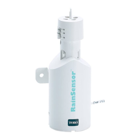
• Designed to connect to a normally-closed sensor (i.e. Toro RainSensor
TM
).
• Fully compatible with Toro and most competitor’s DC latching solenoids
• Station short circuit detection with use of Toro TBC
TM
HH Programmer
• Unique power feature conrms there is sufcient battery power to turn off all stations

4
To replace AC solenoids with DC Latching solenoids
Step 1 –
Locate and shut off the
water supply that services
the irrigation system.
Step 2 –
Disconnect the wiring
from the existing solenoid
and unscrew it from the
valve.
Step 3 –
Install the DC Latching
solenoid onto the valve.
Step 4 –
Strip approximately 1/2”
(1.25 cm) of the insulation
from the DC Latching
solenoid’s wires.
Step 5 –
Refer to “Connecting The
Valve” section on page 5
for wiring instruction and diagram.
NOTE:
The use of Toro DC latching solenoids is recommended.
24 VAC Solenoid 9 VDC Latching Solenoid

5
Connecting the Valve
The TBC
TM
WP controller can only operate valves equipped with a DC Latching solenoid. Verify
that the device being controlled is equipped with the proper solenoid.
Connecting the Valves
Step 1 –
If connecting more than one valve,
determine the station designation
for each valve. For programming
purposes, note the zone that each
valve/station will service.
Step 2 –
Connect the TBC
TM
WP controller’s
station 1 wire to the positive (red)
wire lead from Station 1 solenoid.
Connect the TBC
TM
WP controller’s
C (common) wire (black) to the
negative (black) solenoid wire.
Connect the remaining Station
wires (colored) to their respected
soleoid wires in the same manner.
NOTE:
Use water sealed/
proof wire connectors (not
supplied) for this application.
Step 3 –
Check the valve(s) and controller for proper operation. (Refer to TBC
TM
HH User’s
Guide for operation.)
Station 1
Station Wire Color
1 Red
2 Orange
3 Gray
4 Green
5 Blue
6 Brown
Station 2 Station 3

6
Connecting the Rain Sensor
The TBC
TM
WP sensor is designed for a normally closed sensor.
The following example will illustrate how to connect a wired Toro RainSensor
TM
to the
controller. Other normally closed sensors can be installed to the controller as well, such as
moisture, rain, etc.
Step 1 –
Route wires from the rain sensor to
the TBC
TM
WP controller.
Step 2 –
Cut the wire loop (yellow) from
TBC
TM
WP controller’s Sensor A and B.
Strip approximately 1/2" (1.25 cm)
of insulation from the wires and
connect them to the rain sensor wires.
Wire polarity is not observed in this
application.
NOTE:
Use water sealed/proof
wire connectors (not supplied) for this
application.
IMPORTANT:
If a rain sensor is not
installed, the TBC
TM
WP controller’s
Sensor A and B wires must be
connected together. Otherwise, the
controller will assume that rain is
being detected and it will prevent
programs from activating.

7
Battery Installation
The TBC
TM
WP controller is powered by two 9 VDC alkaline batteries (not supplied). The use
of two high-quality alkaline batteries is recommended to maximize performance. Fresh high
quality batteries will provide sufcient power to last an entire irrigation season.
Step 1 –
Unscrew the battery cap to
access the battery compartment.
Step 2 –
Install two 9 VDC alkaline
batteries onto the two battery
connectors located inside the
compartment.
IMPORTANT:
Make sure no
water is present in the battery
compartment.
Step 3 –
Position the batteries inside the
compartment and replace the
cover.
NOTE:
Hand-tighten the
battery cap only. Do not over
tighten.
The cap is equipped with
a gasket and an O-ring to provide a waterproof seal. Over tightening the cap might
damage these seals.

8
Installing the TBCTMWP Controller Module
Install the TBC
TM
WP controller next to the valve(s), inside a valve box.
Step 1 –
Position the TBC
TM
WP controller
inside the valve box. Select a
position such that the battery
compartment and the IR port can
be easily accessed. Mark the
screw hole position on the valve
box.
Step 2 –
Secure the two mounting screws
on the marked location. Leave
approximately 1/4" (6mm) of the
exposed screw.
Step 3 –
Hang the controller onto the
screws. Verify that the screws are
seated properly at the top of the
keyhole slot.
Step 4 –
Tighten the screws to secure the
controller.
IMPORTANT:
For controller
with integrated radio interface,
position the antenna upright for
optimum performance.
Step 5 –
Write the hand-held and controller module numbers on the provided label.
See TBC
TM
HH manual for details.
TBCWP

9
Troubleshooting Guide
The following problem samples are listed to help you troubleshoot your TBC
TM
WP controller in
case you encounter performance issues.
Many of the problems involving the TBC
TM
WP controller are commonly associated with
transmission/reception. These are usually caused by low battery power or improper battery
connection. Other causes can also be improper wire connections or a dirty IR connector.
Problem: Faulty Transmission
Possible Cause: Low battery power
Solution: Replace the batteries
Possible Cause: Improper battery connection
Solution: Verify that the batteries are connected properly
Possible Cause: The TBC
TM
WP controller IR port is dirty
Solution: Clean the TBC
TM
WP IR port
Possible Cause: Improper connection between hand held and controller
Solution: Reconnect the IR port and verify that connection is secure
Possible Cause: The TBC
TM
WP microprocessor did not properly reset
Solution: Reset the controller by removing the batteries from the controller.
Ground both battery lead terminals for 1-minute. Reinstall the batteries.
Possible Cause: If using the integrated radio, the controller and hand held identication
codes do not match.
Solution: Reset the controller by removing the batteries from the controller. Ground
both battery lead terminals for 1-minute. Follow the controller setup in
the TBC
TM
HH User’s Guide.

10
Problem: Station Fails to Start
Possible Cause: No programmed station run time.
Solution: Modify program to include station run time.
Possible Cause: The On-Off mode is activated.
Solution: Enable irrigation by deactivating On-Off mode.
Possible Cause: Low battery power.
Solution: Replace the batteries.
Possible Cause: Improper wire connection.
Solution: Verify the wire connections. If necessary, redo the splices and connectors.
Possible Cause: TBC
TM
WP sensor input is active.
Solution: If a rain sensor is not installed, verify that Sensor A & B wires are connected
together. If a sensor is installed, verify proper operation of that sensor.
Possible Cause: Short circuit in the solenoid or the wiring to the solenoid.
Solution: Verify with TBC
TM
WP Programmer that a short was detected on the station.
If a short is detected, replace the solenoid and/or wiring to the solenoid.
Possible Cause: Improper solenoid operation.
Solution: Repair or replace solenoid.
Problem: Station stops when it should start or vice versa
Possible Cause: Station wires are reversed.
Solution: Verify that the DC Latching solenoid’s colored wire is connected to the
TBC
TM
WP station wire. Verify that the black solenoid wire is connected to the
TBC
TM
WP common (C) terminal.
Possible Cause: Solenoid is out of phase with the controller.
Solution: Reset the controller. During the start-up, the controller will synchronize with
the solenoid.

11
Limited Three-Year Warranty
The Toro Company and its afliate, Toro Warranty Company, pursuant to an agreement between
them, jointly warrants, to the owner, against defects in material and workmanship for a period of
three years from the date of purchase.
Neither The Toro Company nor Toro Warranty Company is liable for failure of products not
manufactured by them even though such products may be sold or used in conjunction with Toro
products.
During such warranty period, we will repair or replace, at our option, any part found to be defective.
Return the defective part to the place of purchase.
Our liability is limited solely to the replacement or repair of defective parts. There are no other
express warranties.
This warranty does not apply where equipment is used, or installation is performed, in any manner
contrary to Toro’s specications and instructions, nor where equipment is altered or modied.
Neither The Toro Company nor Toro Warranty Company is liable for indirect, incidental or
consequential damages in connection with the use of equipment, including but not limited to:
vegetation loss, the cost of substitute equipment or services required during periods of malfunction
or resulting non-use, property damage or personal injury resulting from installer’s negligence.
Some states do not allow the exclusion or limitation of incidental or consequential damages, so the
above limitation or exclusion may not apply to you.
All implied warranties, including those of merchantability and tness for use, are limited to the
duration of this express warranty.
Some states do not allow limitations of how long an implied warranty lasts, so the above limitation
may not apply to you.This warranty gives you specic legal rights and you may have other rights
which vary from state to state.

12
FCC Compliance Information
This equipment generates and uses radio frequency energy and if not installed and used
properly, that is, in strict accordance with the manufacturer’s instructions, may cause
interference to radio and television reception. It has been type tested and found to comply
with the limits for a FCC Class B computing device in accordance with the specications
in Subpart J of Part 15 of FCC Rules, which are designed to provide reasonable protection
against such interference in a residential installation. However, there is no guarantee that
interference will not occur in a particular installation. If this equipment does cause interference
to radio or television reception, which can be determined by turning the equipment off and
on, the user is encouraged to try to correct the interference by one or more of the following
measures:
• Reorient the receiving antenna.
• Relocate the irrigation controller with respect to the receiver.
• Move the irrigation controller away from the receiver.
• Plug the irrigation controller into a different outlet so that the irrigation controller and receiver
are on different branch circuits.
If necessary, the user should consult the dealer or an experienced radio/television technician
for additional suggestions. The user may nd the following booklet prepared by the Federal
Communications Commission helpful: “How to Identify and Resolve Radio/TV Interference
Problems.” This booklet is available from the U.S. Government Printing Ofce, Washington,
DC 20402. Stock No. 004-000-00345-4.
© 2009 The Toro Company • Irrigation Division • www.toro.com Part Number 373-0498 rev. B
Table of contents
Other Toro Controllers manuals

Toro
Toro TMC-212 User manual

Toro
Toro 119-1100 User manual

Toro
Toro 24 User manual

Toro
Toro TCM-212 User manual

Toro
Toro TEMPUS-AG-MV User manual

Toro
Toro OSMAC RDR Satellite Controller User manual

Toro
Toro TDC-100/200 User manual

Toro
Toro LTC PRO User manual

Toro
Toro TEMPUS DC LCD User manual

Toro
Toro Network VP User manual

Toro
Toro Network LTC Plus User manual
Toro
Toro TDC+ User guide

Toro
Toro NO FOUND TMC-424E User manual
Toro
Toro DDCWP Series User manual

Toro
Toro TEMPUS DC LCD User manual

Toro
Toro GDC 200 User manual

Toro
Toro EVOLUTION Series User manual

Toro
Toro TMC-424 Series User manual

Toro
Toro Intelli-Sense TIS-612 User manual
Toro
Toro Micro-Master Series User manual