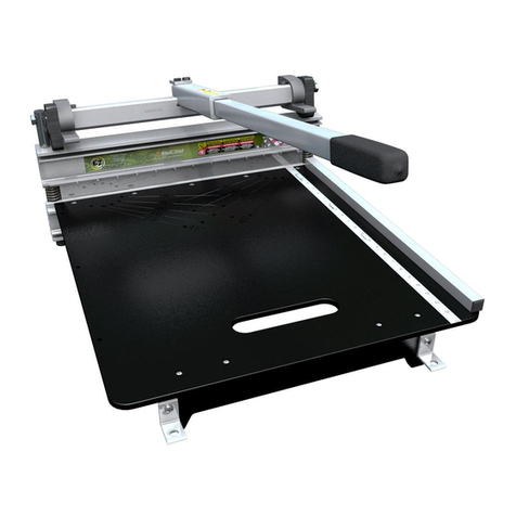
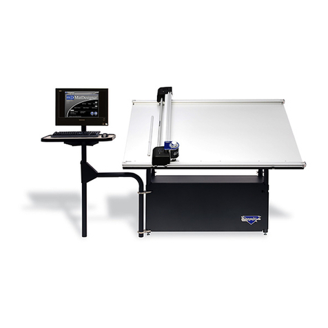
GRAPHTEC FC2240 User manual

CUTTING MACHINE
SERVICE MANUAL
FC2240
FC2240-UM-251-04-9370


FC2240-UM-251-9370 i
HISTORY OF REVISIONS
No. Date issued Description of revision Page Edition
1 05.11.24 First Printing All 01
2 06.04.24 Part number for the Y flexible cable corrected. 10-10 02
3 06.05.26 Part number for the control panel switch corrected. 5-1, 10-5 03
4 06.05.26 Part number for the main relay board corrected. 5-1, 10-5 03
5 06.09.07 Part number for the control panel switch corrected. 5-1 04

FC2240-UM-251-9370 ii
CONTENTS
1. INTRODUCTION .............................................................1-1
1.1 Model Names and Basic Specifications .........................................................1-1
1.2 Standard Accessories ......................................................................................1-1
1.3 Main Specifications ..........................................................................................1-2
1.4 External Dimensions ........................................................................................1-3
1.5 Stand Assembly Procedure .............................................................................1-6
1.6 Mounting Procedure .........................................................................................1-7
1.7 Removing the Y Bar Retaining Brackets ........................................................1-8
1.8 Selecting the Vacuum Pump ............................................................................1-9
1.9 Installation Location .......................................................................................1-10
2. Description of Parts ......................................................2-1
2.1 Plotter Nomenclature .......................................................................................2-1
2.2 Control Panel ....................................................................................................2-2
2.3 Types of Cutter Blades and Their Features ....................................................2-4
2.4 Cutter Pen Nomenclature .................................................................................2-5
3 Basic Operation .............................................................3-1
3.1 Replacing the Cutter Blade ..............................................................................3-1
3.2 Adjusting the Blade Length .............................................................................3-3
3.3 Mounting the Cutter Pen ..................................................................................3-4
3.4 Adjusting the Pen Carriage Height .................................................................3-5
3.5 Turning On the Plotter and Initialization .........................................................3-6
3.6 Loading the Medium .........................................................................................3-7
3.7 PAUSE Menu Configuration .............................................................................3-8
3.8 Setting the Cutting Conditions ........................................................................3-9
3.9 Running a Cutting Test ..................................................................................3-12
3.10 Achieving Optimum Cutting Results ............................................................3-13
3.11 Listing the Cutting Conditions ......................................................................3-14
3.12 Using the Character Dump Mode ..................................................................3-16
3.13 Running the Self Test .....................................................................................3-17

FC2240-UM-251-9370 iii
4. Daily Maintenance and Storage ...................................4-1
5. RECOMMENDED PARTS LIST .....................................5-1
6. LIST OF TOOLS .............................................................6-1
6.1 Tools ..................................................................................................................6-1
7. DISASSEMBLY AND ADJUSTMENT ............................7-1
7.1 Adjusting the X-Axis Drive ...............................................................................7-1
7.1.1 Removing the X Motor Cover ................................................................................................................. 7-1
7.1.2 Adjusting the X Drive Belt Tension ........................................................................................................ 7-1
7.1.3 Adjusting the Belt Tension of the Front X Slider .................................................................................. 7-2
7.1.4 Adjusting the Belt Tension of the Rear X Slider ................................................................................... 7-2
7.1.5 Checking the Belt Tension of the Front and Rear X Sliders ................................................................ 7-3
7.2 Adjusting the Y-Axis Drive ...............................................................................7-4
7.2.1 Removing the Y Motor Cover ................................................................................................................. 7-4
7.2.2 Removing the Y Motor ............................................................................................................................. 7-4
7.2.3 Adjusting the Y Drive Belt Tension ........................................................................................................ 7-6
7.3 Adjusting the Y Slider ......................................................................................7-7
7.3.1 Removing the Y Bar ................................................................................................................................. 7-7
7.3.2 Adjusting the Y Slider Belt Tension ....................................................................................................... 7-8
7.4 Adjusting the Roller Pressure of the Front X Slider ......................................7-9
7.5 Adjusting the Roller Pressure of the Rear X Slider .....................................7-10
7.6 Adjusting the Roller Pressure of the Y Slider ..............................................7-12
7.7 Adjusting the Position of Sensor Dog Y .......................................................7-13
7.8 Mounting the Y Slider on the Y Flexible Printed Circuit Cable ...................7-14
7.9 Pen Block ........................................................................................................7-15
7.9.1 Removing the Pen Block Cover ........................................................................................................... 7-15
7.9.2 Removing the Pen Block ...................................................................................................................... 7-15
7.9.3 Adjusting the Pen Block ....................................................................................................................... 7-16
7.10 Using the Mechanical Adjustment Jigs ........................................................7-18
7.11 Replacing the Y Bar ........................................................................................7-19
7.11.1 Preparations ........................................................................................................................................... 7-19
7.11.2 Replacing the Y Bar ............................................................................................................................... 7-19
7.11.3 Checking the Sliding of the Y Bar Frame (Manual Check) ................................................................. 7-20
7.12 Adjusting the Perpendicularity Precision ....................................................7-21
7.12.1 Checking the Deviation in the Perpendicularity ................................................................................. 7-21

FC2240-UM-251-9370 iv
7.13 Replacing the Electrostatic Adhesion Plate .................................................7-23
7.13.1 Peeling Off the Electrostatic Adhesion Plate ...................................................................................... 7-23
7.13.2 Preliminary Preparations for Pasting On New Plate .......................................................................... 7-23
7.13.3 Attaching the Electrostatic Adhesion Plate ........................................................................................ 7-25
8. ELECTRICAL ADJUSTMENTS ......................................8-1
8.1 Flowchart of the Adjustment Sequence ........................................................8-1
8.2 Location of the Boards .....................................................................................8-2
8.2.1 Main Relay Board (PN5042-01) ............................................................................................................... 8-3
8.2.2 X Flex. Board (PR223226) ....................................................................................................................... 8-3
8.3 Setting the Power Unit’s Supply Voltage (PS089B) .......................................8-4
8.4 Checking the Power Unit’s Supply Voltage ....................................................8-5
8.4.1 Checking the Voltage Levels .................................................................................................................. 8-5
8.4.2 The Protective Circuit ............................................................................................................................. 8-5
8.5 Explanation of the Values of the Main Board .................................................8-6
8.6 Setting the DIP Switches ..................................................................................8-7
8.7 Updating the System Firmware .......................................................................8-8
8.8 Clearing the Non-Volatile RAM ......................................................................8-10
8.9 Adjusting the Home Position .........................................................................8-12
8.10 Adjusting the Pen Height ...............................................................................8-13
8.11 Adjusting the Pen Force ................................................................................8-14
8.12 Adjusting the Distance and the Perpendicularity Accuracy .......................8-16
8.13 Adjusting the Pen Interval .............................................................................8-18
8.14 DIP Switch Factory Settings ..........................................................................8-19
8.15 Factory Preset Settings ..................................................................................8-19
8.16 Testing the Control Panel Keys and Home Sensors ...................................8-21
8.17 List of Items Requiring Readjustment ..........................................................8-23
9 TROUBLESHOOTING ....................................................9-1
9.1 Troubleshooting Flowcharts ............................................................................9-1
9.1.1 Checking for Faulty Rotation of the Blade ............................................................................................ 9-1
9.1.2 The Cutting Media Cannot be Satisfactorily Cut .................................................................................. 9-2
9.1.3 Initialization is Abnormal ........................................................................................................................ 9-8
9.1.4 Pen UP/DOWN Operations are Abnormal .............................................................................................. 9-9
9.1.5 The X-axis Backlash is Excessive ........................................................................................................9-11
9.1.6 The Y-axis Backlash is Excessive ........................................................................................................ 9-12

FC2240-UM-251-9370 v
9.2 The Plotter is Turned On But Doesn’t Operate ............................................9-13
9.3 Error Messages ...............................................................................................9-14
9.4 Error Messages in GP-GL Command Mode .................................................9-15
9.5 Error Messages in HP-GL Emulation Mode ..................................................9-16
9.6 The Cutting Results are Unsatisfactory .......................................................9-18
10. PARTS LISTS ...............................................................10-1
10.1 Mainframe ........................................................................................................10-1
10.2 Stand ................................................................................................................10-3
10.3 Control Panel ..................................................................................................10-4
10.4 Control Unit .....................................................................................................10-5
10.5 X Drive Unit .....................................................................................................10-6
10.6 Y Drive Section ...............................................................................................10-9
10.7 Standard Accessories ..................................................................................10-12
11. BLOCK DIAGRAMS AND CIRCUIT DIAGRAMS ........ 11-1
11.1 Wiring Connection ..........................................................................................11-1
11.2 Key Relay Board (PR223281) .........................................................................11-3
11.3 Main Relay Board (PN5042-01A) ...................................................................11-4
11.4 X Relay Board (PR223203) .............................................................................11-6
11.5 X Flex. Board (PR223224A) ............................................................................11-7
11.6 X-Y Relay Board (PN5042-02A) ......................................................................11-8
11.7 Pen Flex. Board (PR223226A) ........................................................................11-9
11.8 2-Pen Relay Board (PR223229A) .................................................................11-10
11.9 2-Pen Board (PR223227A) ............................................................................ 11-11
11.10 High Voltage Board (PR31001C) ..................................................................11-12
11.11 Main Board (PR306101) ...............................................................................11-13
11.12 Miscellaneous ...............................................................................................11-25

FC2240-UM-251-9370 vi

FC2240-UM-251-9370 1-1
1. INTRODUCTION
1. INTRODUCTION
1.1 Model Names and Basic Specifications
Model No. of pens Media hold down method Cutting area
FC2240-60VC 2 Vacuum suction 610 (X) x 920 (Y) mm
FC2240-120MG 2 Magnetic
1200 (X) x 920 (Y) mmFC2240-120ES 2 Electrostatic adhesion
FC2240-120VC 2 Vacuum suction
FC2240-180ES 2 Electrostatic adhesion 1740 (X) x 920 (Y) mm
FC2240-180VC 2 Vacuum suction
1.2 Standard Accessories
Item Description Q’ty
Power cable 1
Cutter pen set PPA31-CB15B, CB15U-2SP, CB15U-K30-5SP 1 set
Water based fiber-tip pen KF552-BK 1
Sheet holder plates For MG models only (2 large, 2 medium, 4 small) 1 set
Hexagon wrench For M4 bolts 1
Height adjustment plates 10 mm, 4 mm height 1 of each
Paper alignment seals 1 pack
Durable flexible hose For VC models only, 1.5 m to 5 m (can expand/contract)
Connection bore diameter: Ø38mm (-60), Ø58mm (-120/180) 1
Hose band For VC models only 2
Vacuum pump installation base For VC models only 1
CD-ROM User’s manual, Driver, other software 1
CAUTION
• The vacuum pump is an option. It is not provided with the VC models.
• Make sure that the vacuum pump used with a VC model is affixed with either a label showing compliance
with the relevant safety standard or with the CE marking.

FC2240-UM-251-9370 1-2
1. INTRODUCTION
1.3 Main Specifications
FC2240-60VC FC2240-120VC/MG/ES FC2240-180VC/ES
Configuration Flatbed
Effective cutting area 610 x 920 mm 1200 x 920 mm 1740 x 920 mm
Media hold-down method VC models: Vacuum suction, MG models: Magnetic,
ES models: Electrostatic adhesion
Maximum cutting speed 400 mm/sec (40-step range)
Cutting force High force mode: 9.8 N (1 kgf) max : 40-step range 2 to 80
Standard force mode: 4.9 N (500 gf) max : 40-step range 1 to 40
Minimum character size About 10 mm square (varies with the character font and cutting media)
Mechanical resolution 0.0025 mm
Programmable resolution GP-GL mode: 0.1/0.05/0.025/0.01 mm, HP-GLTM mode: 0.025 mm
Distance accuracy Within 0.1% of the distance moved (plotter mode)
Perpendicularity Within 0.5 mm/900 mm (plotter mode)
Repeatability Within 0.1 mm (plotter mode)
Number of pens/cutters 2
Cutter and pen types Cutter blades: Supersteel
Pens: water-based fibertip, oil-based ballpoint, disposable ink pen*1
Cutting media Marking film (vinyl, fluorescent, reflective), Stiff paper/card up to 0.5 mm
thick, Sandblast rubber sheets up to 1 mm thick, High-intensity reflective
film. Polystyrene foam sheets
Interfaces RS-232C, Centronics, USB 2.0 (full speed); auto-switching
Buffer memory 2 MB
Command sets GP-GL and HP-GLTM emulation
LCD panel 20 characters x 2 lines
Power supply 100-120 VAC, 50/60 Hz, 1.2 A max
220-240 VAC, 50/60 Hz, 0.7 A max
Operating environment 10 to 35˚C, 35 to 75% RH (non-condensing)
Guaranteed precision
operating environment
16 to +32˚C, 35% to 70% RH (non-condensing)
External dimensions
(H x W x D) Horizontal 857 x 920 x 1285 mm 944 x 1568 x 1285 mm 944 x 2068 x 1285 mm
Tilted ----*2 1687 x 1568 x 987 mm 1687 x 2068 x 987 mm
Weight (including stand) Approx. 58 kg Approx. 69 kg Approx. 74 kg
Option Vacuum pump (Blower) [VC models only]
*1: Disposable ink pens cannot be used with the high-force pen (Pen 2 holder).
*2: The writing panel on VC models cannot be tilted.

FC2240-UM-251-9370 1-3
1. INTRODUCTION
1.4 External Dimensions
FC2240-60VC
1285
920
720
910
857
790 67
58 1040
Unit: mm
Dimensional accuracy: ±5 mm

FC2240-UM-251-9370 1-4
1. INTRODUCTION
FC2240-120
Unit: mm
Dimensional accuracy: ±5mm
526
877
944
67
1687
5
8
9
0
4
0
11
0
12
70011261
8651
1285
FC2240-120

FC2240-UM-251-9370 1-5
1. INTRODUCTION
FC2240-180
Unit: mm
Dimensional accuracy: ±5mm
526
877
944
67
1687
589
0
401 10
127 0
061
2
61
86
02
1285
FC2240-180

FC2240-UM-251-9370 1-6
1. INTRODUCTION
1.5 Stand Assembly Procedure
Assembly Procedure
Attach the two center plates (3) to the stand leg (1), using the M6 x 15 bolts and the L wrench provided as
standard accessories.
Attach the center plates (3) to stand leg (2) in the same way.
Standard accessories
1. M6 x 15 hexagonal bolts: 8
2. L wrench
M6 x 15 hexagonal bolts

FC2240-UM-251-9370 1-7
1. INTRODUCTION
1.6 Mounting Procedure
Screws provided for assembly
1. M4 x 8 bind-head screws: 8
2. M3 x 8 bind-head screws: 6
Procedure
(1) When mounting the FC2240 unit onto the stand, make sure that it is correctly oriented. The three cables
protruding from the FC2240 should be at the control box side.
(2) Position the FC2240 so that the underside of the frame is mounted on top of the stand.
After the FC2240 unit has been mounted on the
stand, insert the cables protruding from the underside
into the control panel box.
The control panel box is affixed to the side of the stand with
four M3 x 8 screws at the top and two at the bottom.
To facilitate the mounting of the control box on the stand,
insert the screws into the stand side first, leaving a gap,
and then mount the control box.
Control box
Note:
The surface with the M3 tapping screws
is the surface on which the control box is mounted.
FC2240 frame
Two L-shaped brackets
FC2240 frame
Two L-shaped brackets
Screw in the M4 x 8 screws into the
brackets from the underside.
There are two screws each at four
locations, for a total of eight screws.

FC2240-UM-251-9370 1-8
1. INTRODUCTION
1.7 Removing the Y Bar Retaining Brackets
(1) Use the L wrench supplied as a standard accessory to loosen the M3 hexagonal bolts.
Front
Expanded view F
Turn the M3 bolts
counterclockwise
to loosen them
Retaining bracket FR
Retaining bracket FL
Expanded view F
Turn the M3 bolts
counterclockwise
to loosen them
Turn the M3 bolts
counterclockwise
to loosen them
Turn the M3 bolts
counterclockwise
to loosen them
(2) Loosen the M3 bolts as shown in the illustration above, and then move the FL and FR retaining brackets
to the front, in a horizontal direction. Next, pull the brackets out in an upward direction. Use the L wrench
supplied as a standard accessory.
CAUTION (IMPORTANT)
Move the plate nuts inside the pressed aluminum
fitting to the left edge, and then tighten the M3 bolts.
Movetheplate nuts
to theleft edge.
Tightenthetwo M3 bolts.
Expanded view R
Remove the M3 hexagonal bolts
Pull the bracket out in an upward direction.
The plate nuts are on the far side of the bolts.
Move the plate nuts as is to the left edge, and
then fasten in place with the M3 bolts that were
removed.
Retaining bracket R Rear
Expanded view R
(3) Loosen the two M3 hexagonal bolts as shown in the above diagram, and then pull bracket R out in an
upward direction.

FC2240-UM-251-9370 1-9
1. INTRODUCTION
1.8 Selecting the Vacuum Pump
Select the vacuum pump according to the guidelines listed in the table below.
Item FC2240-60VC/120VC/180VC
Ratings Airflow (m3/min) 0.5
Static pressure (kPa) 6.4
Hose connection bore 50 mm
CAUTION
Make sure that the vacuum pump used with a VC model is affixed with either a label showing compliance
with the relevant safety standard or with the CE marking.
The figure below shows the dimensions of the vacuum pump installation base provided.
330
6
9
1
0
467
190
4-�10
42.5
496
4
13
5
0
2
5
22
95
4-�12
4-�10
174.5
83150.5
FC2240-60VC
FC2240-120VC
FC2240-180VC

FC2240-UM-251-9370 1-10
1. INTRODUCTION
1.9 Installation Location
When connecting the vacuum pump to your cutting plotter, please refer to the following diagram.
CAUTION
The exhaust from the vacuum pump is hot, so do not place anything flammable near the exhaust port.
Failure to observe this precaution could cause a fire.
Hose band
Hose band
CA2294-03 CA2294-02
CA2294-01
Vacuum pump
Durable flexible hose
Connect to the power outlet
Hose band
Hose band
Vacuum pump
CA2294-03
CA2294-02
CA2294-01
Connect to the
power outlet
Durable flexible hose
FC2240-60VC
FC2240-120VC
FC2240-180VC
CHECKPOINT
A vacuum pump is not provided.

FC2240-UM-251-9370 2-1
2. Description of Parts
2. Description of Parts
2.1 Plotter Nomenclature
The names of the plotter parts are as follows.
Pen carriage Y ber
Control panel
Tilt lever
CHART HOLD key
(ES models only)
Writing panel
Stand
Power switch
Power inlet
Interface connector
Rear view of
the main box
USB interface
Parallel interface
RS-232C interface
PARA LLEL
RS-232C

FC2240-UM-251-9370 2-2
2. Description of Parts
2.2 Control Panel
Indicator Lamps
......................The POWER lamp remains lit (green) while the plotter is on.
...................The PROMPT lamp lights (red) when the plotter receives data that will cause
the pen carriage to move outside the effective cutting area or receives the
“Prompt Light” command (T) from the computer.
CHART HOLD
(ES [electrostatic adhesion] models only)
.............................................Press the [CHART HOLD] key to enable the electrostatic adhesion function
(the key’s lamp lights). Press it again to cancel the electrostatic adhesion
function (the lamp goes off).
Panel Keys
..................... Depending on the menu being displayed, these keys are used to:
• Load a group of cutting conditions retained in the plotter’s memory;
• Shift the cursor when setting a numeric value for a function;
• Select the desired submenu.
................. • All four keys are used to move the pen carriage when setting a function that
requires the specification of a coordinate position.
• The [ ] and [ ] keys are used to raise or lower the displayed numeric
setting of a function.
• The [ ] and [ ] keys are used to select the pen type when setting a group
of cutting conditions.
• Press the [ ] key and the [ENTER] key concurrently to move the pen
carriage to the upper right position and facilitate loading of the cutting
medium.
......................... Used to repeat the cutting operation defined by the data in the plotter’s receive
buffer.
....................... Used to set the eight groups of cutting conditions retained in the plotter’s
internal memory or to select one group as the current cutting conditions.
......................... Used to select the desired menu screen for setting a function at the control
panel when the plotter is in PAUSE mode.
This manual suits for next models
6
Table of contents
Other GRAPHTEC Cutter manuals
GRAPHTEC
GRAPHTEC FC5100-75 User manual
GRAPHTEC
GRAPHTEC FC8000 Series User manual
GRAPHTEC
GRAPHTEC FC4500 User manual

GRAPHTEC
GRAPHTEC FCX2000 SERIES User manual
GRAPHTEC
GRAPHTEC CE LITE-50 User guide
GRAPHTEC
GRAPHTEC CB15U User manual

GRAPHTEC
GRAPHTEC FCX4000 SERIES User manual
GRAPHTEC
GRAPHTEC CUTTING PRO FC3100-60 User manual
GRAPHTEC
GRAPHTEC CE5000 SERIES User manual
