FormNo.3419-198RevB
4045DirectionalDrill
SoftwareVersionsA–C
ModelNo.23823/A/C/TE/W—SerialNo.315000001andUp
ModelNo.23825/A/C/TE/W—SerialNo.315000001andUp
SoftwareGuide
Readthisinformationcarefullytolearnhowtooperate
andmaintainyourproductproperlyandtoavoid
injuryandproductdamage.Youareresponsiblefor
operatingtheproductproperlyandsafely.
Wheneveryouneedservice,genuineT oroparts,or
additionalinformation,contactanAuthorizedService
DealerorT oroCustomerServiceandhavethemodel
andserialnumbersofyourproductready.
YoumaycontactTorodirectlyatwww.T oro.com
forproductsafetyandoperationtrainingmaterials,
accessoryinformation,helpndingadealer,orto
registeryourproduct.
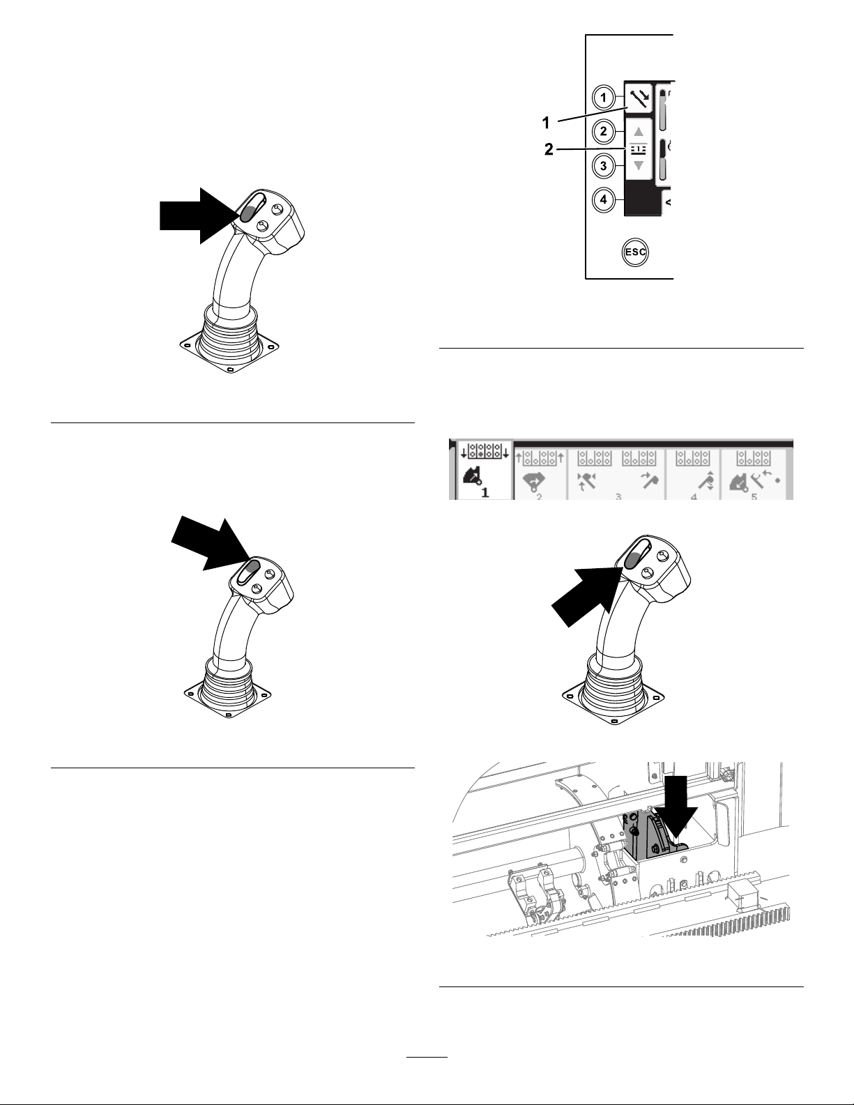
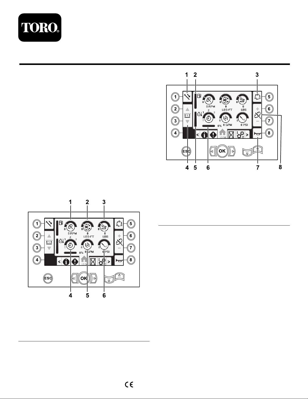
MainInformationScreen
Thisistherstscreenthatappearsaftertheinitial
splashscreen.T onavigatebetweenscreens,usethe
leftandrightarrows.
g214633
Figure1
1.Drillspeed(rpm)4.Enginespeed(rpm)
2.Rotarytorque5.Drilling-uidowrate
3.Thrustforce6.Drilling-uid/Air-hammer
pressure
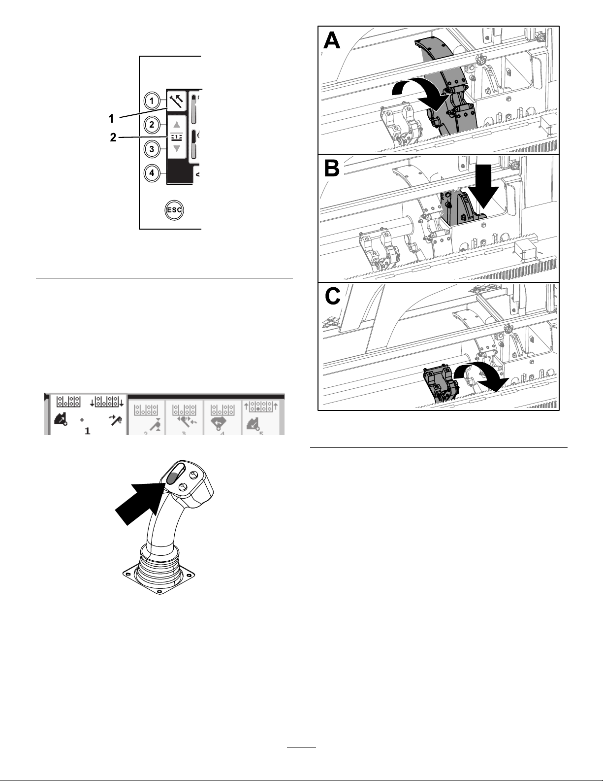
g214634
Figure2
1.Pipefunctions5.Enginetemperaturegauge
2.Fuelgauge6.Enginedroop
3.Limitsettingoptions7.Horn
4.Selectpiperow8.Thrustforce,drillspeed
(rpm),orrotarytorque
adjustment
GototheMudorAirHammerSelectionScreen(page
12)toswitchbetweenmudpressureandairhammer
functions.
Pushbutton1toswitchbetweenthepipefunctions
pullpipe,pushpipe,andneutral.
Pushbutton5toswitchbetweenthrustforce,drill
speed(rpm),androtarytorquelimits.
Usetheupanddownarrowstosetthelimitsfor
maximumdrillspeed(rpm),rotarytorque,andthrust
force.
•Thrustforce:Changethethrustforcelimitby
pushing6or7.
•Drillspeed(rpm):Changethedrillspeedrpmlimit
bypushing6or7.
•Rotarytorque:Changetherotarytorquelimitforce
bypushing6or7.
©2019—TheToro®Company
8111LyndaleAvenueSouth
Bloomington,MN55420
Registeratwww.Toro.com.OriginalInstructions(EN)
PrintedintheUSA
AllRightsReserved*3419-198*B