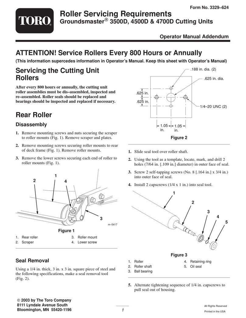
InstallingtheNew
Components(Fig.1)
1.LubricateandinstallthenewO-ringsontothe
ttingspreviouslyremovedfromthewheelmotors.
2.Installthettingsintothewheelmotorports,
orientatingthemasnotedintheremovalprocess.
Note:Theleftwheelmotorisidentiedwitheither
ayellowdotorwitharingmachinedintotheshaft
ofthemotor,showninFigure2.
Figure2
1.Machinedringinshaft
3.Positionthewheelmotortoframe.Mountthespring
clip,brakeadapterandthewheelmotortotheframe
with(4)1/2x3inchcapscrews.
4.Installandtightenthe(4)1/2inchlocknutsonto
thecapscrewstosecurethemotor,brakeadapterand
springcliptotheframe.Torquethescrewsto67to
83ft-lb(91to113N-m).Makesurespringclipis
positionedasshowningureFigure1.
5.Mountthebrakeassemblytothebrakeadapterwith
(4)3/8x3/4inchcapscrews.Torquethecapcrews
to27to33ft-lb(27to45N-m).
6.Thoroughlycleanthewheelmotorshaftandwheel
hubtaper.Donotapplyanti-seizeorgreaseto
thehuborwheelmotorshaft.
7.Installthenewsquarekeyintothewheelmotorshaft
keyslot.Alignthewheelhubwiththesquarekey
andslidethewheelhubontothemotorshaft.Secure
thehubwiththelocknut.Torquethelocknutto405
to495ft-lb(549to671N-m).
Important:Useofatorquemultiplierwitha
standardtorquewrenchisnotrecommended,
butisapossiblealternativetohavingatorque
wrenchcapableof500ft-lbs(678N-m).
8.Iftherearesignsofinternalwheelmotororhydrostat
damage(i.e.metalordebrisinthehydraulicuid,
lossoftractionortractionperformanceproblems,
etc.),specictestingandushingproceduresmust
beperformed.Contactyourlocaldistributorfor
additionalinformation.
9.Removethecapsorplugsfromthedisconnected
hydrauliclinesandttings
10.LubricateandpositionthenewO-ringsontothe
wheelmotorhydraulicttings.Installthehydraulic
linestowheelmotorttingspositioningthemas
notedintheremovalprocess.
11.Securethebrakecableclevistothebrakeactuator
leverwithaclevispinandcotterpin.
12.Installthebrakedrum,frontwheelandextension
springtothemachine.Torquethelugnutsto70to
90ft-lb(95to122N-m).
Note:Onmodels03670,03680and03690with
serialnumberspriorto270001500,andmodel03660
withserialnumberspriorto280000000,thebrake
drum,partno.108-6980,mustbereplacedwith
brakedrum,partno.114-8864.
13.Repeattheprocedureontheoppositewheelmotor.
14.Installthenewhydraulicltersasfollows:
•Cleantheareaaroundthechargecircuit/steering
lter(86–3010)mountingareaandplaceadrain
panunderlter.
•Removethelter.
•Lubricatethegasketonthenewlterwith
hydraulicoil.
•Ensurethattheltermountingareaisclean.
•Installthelterbyhanduntilthegasketcontacts
themountingsurface,thenrotateitanadditional
1/2turn.
•Repeattheprocedureonthereservoirlter
(94–2621).
•Starttheengineandletitrunforabouttwo
minutestopurgeairfromthesystem.
•Stoptheengineandcheckforleaks
15.Checkthehydraulicsystemoillevelandreplenish
asneeded.
16.Testrunthemachineforashortperiodtocheckall
connectionsforleakspriortoinstallingthewheels.
17.Recheckthehydraulicsystemoillevelandreplenish
asneeded.
18.Removethejackstandsandtestdrivethemachineto
checkperformance.
3
