Toro 02917 User manual

FormNo.3412-264RevA
RoadLightswithBrakeLightsKit
Groundsmaster®3400TractionUnit
ModelNo.02917—SerialNo.400000000andUp
InstallationInstructions
Thiskitisdesignedtoprovideafullsetofroadlightswithmountingbracketsandoperationswitches.
Installation
LooseParts
Usethechartbelowtoverifythatallpartshavebeenshipped.
ProcedureDescriptionQty.Use
1Nopartsrequired–Preparethemachine.
Left,rearlightbracket1
Right,rearlightbracket1
Bolt(M16x110mm)2
Nut(M16)2
2
Fuse(15A)2
Installtherearlights.
Dowtyseal(1/4inch)1
Pressureswitchadapter1
Pressureswitch1
3Pressureswitchcable1
Installthepressureswitch.
Numberplatebracket1
2-waytabhousingconnector1
Flasherrelay1
4Standardshorterrelay1
Installthenumberplatebracket.
Centerheadlightmount1
Rightheadlightmount1
Leftheadlightmount1
Bolt(M6x20mm)8
Locknut(M6)8
Bolt(M10x25mm)4
Locknut(M10)4
Washer(3/8inch)8
Mountingbracket2
5
4-waytabhousingconnector2
Installthefrontlights.
Instrumentpanelconnectorlead1
Hazardwarningswitch1
Lightsswitch1
Indicatorswitch1
Hornbutton1
Horndecal1
6
Cabletie24
Installthecontrolpanelswitches.
©2016—TheToro®Company
8111LyndaleAvenueSouth
Bloomington,MN55420
Registeratwww.T oro.com.OriginalInstructions(EN)
PrintedintheUK
AllRightsReserved*3412-264*A

ProcedureDescriptionQty.Use
7Reector2Installthereectors.
8Seriallabel1Installtheseriallabel.
MediaandAdditionalParts
DescriptionQty.Use
InstallationInstructions1Readbeforeinstallingandoperatingkit
PartsCatalog1Usetoreferencepartnumbers
1
PreparingtheMachine
NoPartsRequired
Procedure
1.Parkthemachineonalevelsurface,lowerthecutting
unit,engagetheparkingbrake,shutofftheengine,and
removethekeyfromtheignitionswitch.
2.Disconnectthenegative(–)batterycablefromthe
battery.
WARNING
Gasesthatemitfromthebatteryareexplosive.
Keepopenamesandelectricalsparkaway
fromthebattery.Whenworkingwiththe
battery,wearsafetygogglesandrubbergloves.
Donotsmoke.
2
InstallingtheRearLights
Partsneededforthisprocedure:
1Left,rearlightbracket
1Right,rearlightbracket
2Bolt(M16x110mm)
2Nut(M16)
2Fuse(15A)
Procedure
Note:Ifyouarettingtherearlightstoamachinewith
aserialnumberof316999999andlower,therearlight
mountingbracketsneedtobereplacedwiththebracketsthat
aresuppliedaslooseparts.
Therearlightsattachtotheoutsideoftherollbarpostson
theleftandrightsidesofthemachine.Thelightswillbe
insertedintotheexistingboltholesintherollbar.
1.Opentheenginecover.
2.Lifttheoperatorplatform.
3.Removethebulkheadbehindtheoperator’sseatby
unscrewingthe4bolts(Figure1).
Note:Removingthebulkheadenablesaccesstothe
mainwiringloom.
2

g018276
1
2
g018276
Figure1
1.Bulkhead2.Bolt(4)
4.Ensurethattherollbarpivotboltsandclampboltsare
inplaceandaretight,andorthesecuringpinsarein
placetoretainthetophoop.
5.Removetherollbarpivotboltontheleftsideofthe
machine.
6.Aligntheindicatedholeintheleftrearlightbracket
withtheholeintherollbarandinsertthenewbolt
(M16x110mm),usingtheexistingwashers(Figure
2orFigure3).
g197780
Figure2
Machinewithserialnumbers316999999andlower
1.Bolt(M16x110mm)4.Leftrearlightbracket
2.Existingwashers5.Rollbar
3.Orangeindicatorsideup6.Nut(M16)
g196536
Figure3
Machinewithserialnumbers400000000to999999999
1.Bolt(M16x110mm)4.Rollbar
2.Orangeindicatorsideup5.Existingwasher
3.Leftrearlightbracket6.Nut(M16)
3

7.Installthenewnut(M16)ontotheboltandtorqueit
to15N∙m(11ft-lb).
Note:Donotovertightenitasthiswillmaketheroll
bardifculttofold.
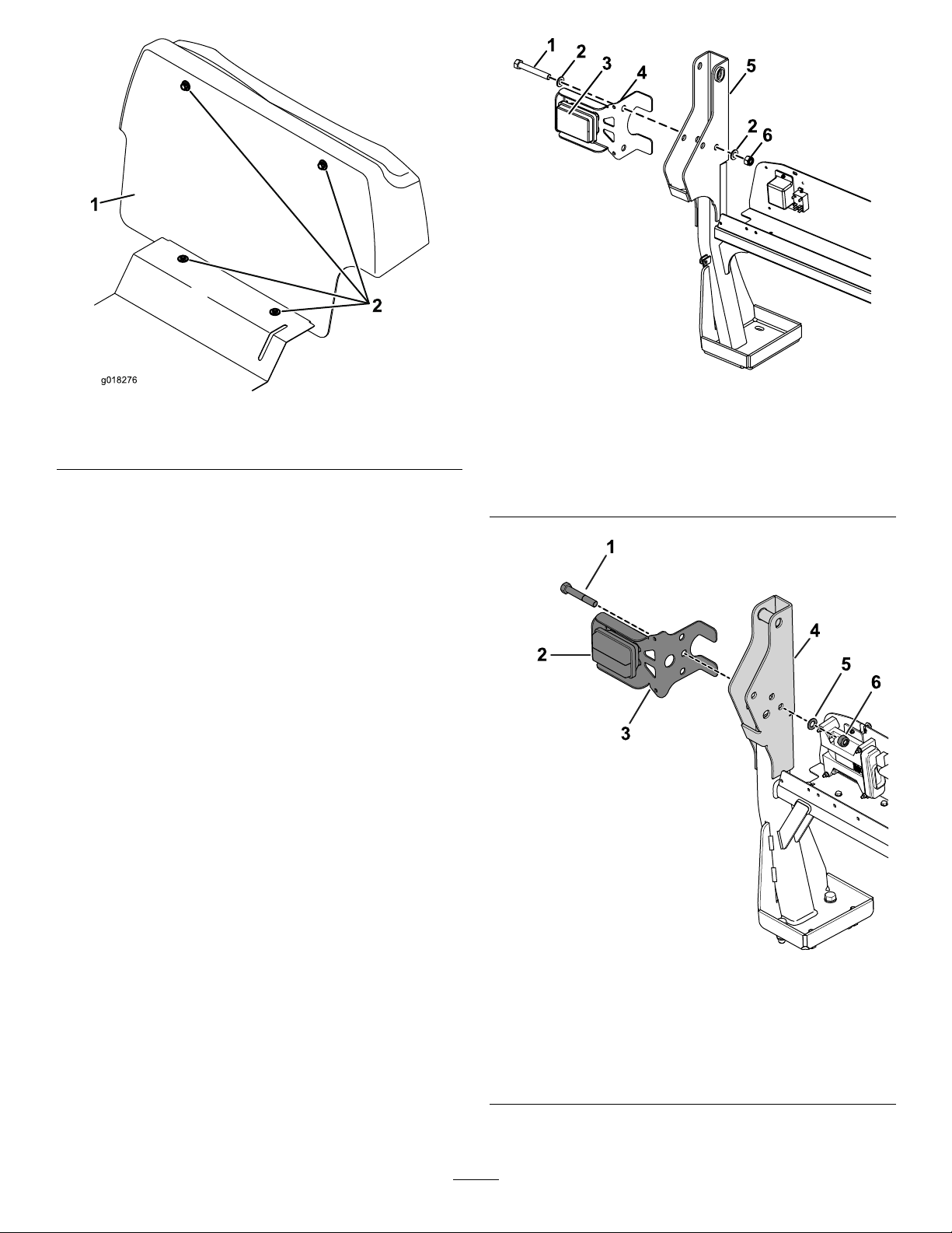
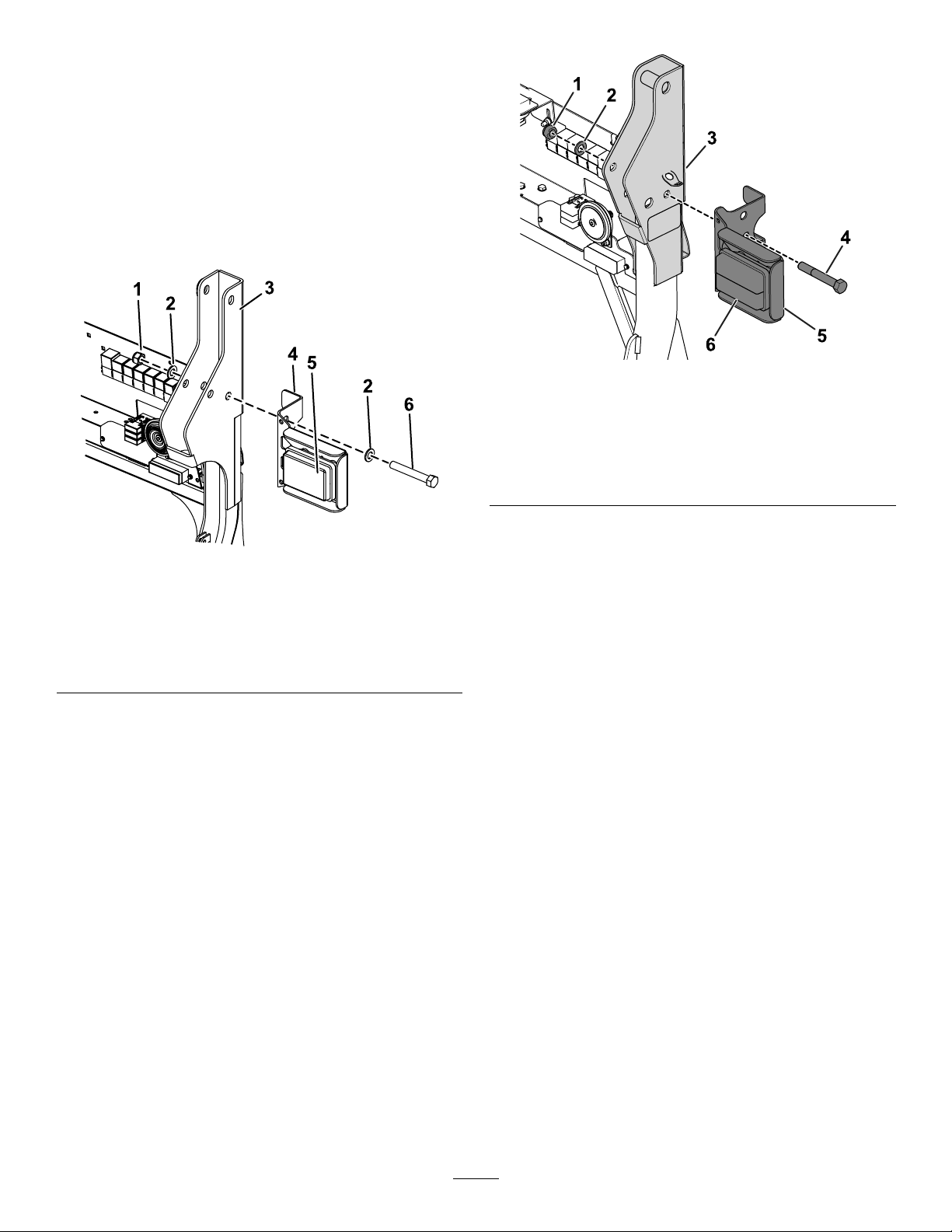
8.Removetherollbarpivotboltontherightsideofthe
mower.
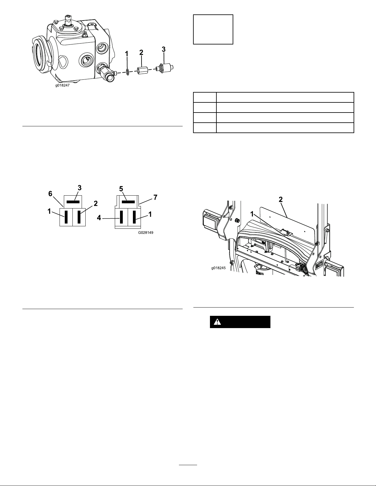
9.Aligntheindicatedholeintherightrearlightbracket
withtheholeintherollbarandinsertthenewbolt
(M16x110mm),usingtheexistingwashers(Figure
4orFigure5).
g197781
Figure4
Machinewithserialnumbers316999999andlower
1.Nut(M16)4.Rightrearlightbracket
2.Existingwashers5.Orangeindicatorsideup
3.Rollbar6.Bolt(M16x110mm)
g196537
Figure5
Machinewithserialnumbers400000000to999999999
1.Nut(M16)4.Bolt(M16x110mm)
2.Existingwasher5.Rightrearlightbracket
3.Rollbar6.Orangeindicatorsideup
10.Installthenewnut(M16)ontotheboltandtorqueit
to15N∙m(11ft-lb).
Note:Donotovertightenthenut,asthismakesthe
rollbardifculttofold.
Note:Ifthereisalreadyabeaconkitttedtotheright
orleftside,usetheexistingboltandthenewnylocnuts
(M16)providedwiththiskit.
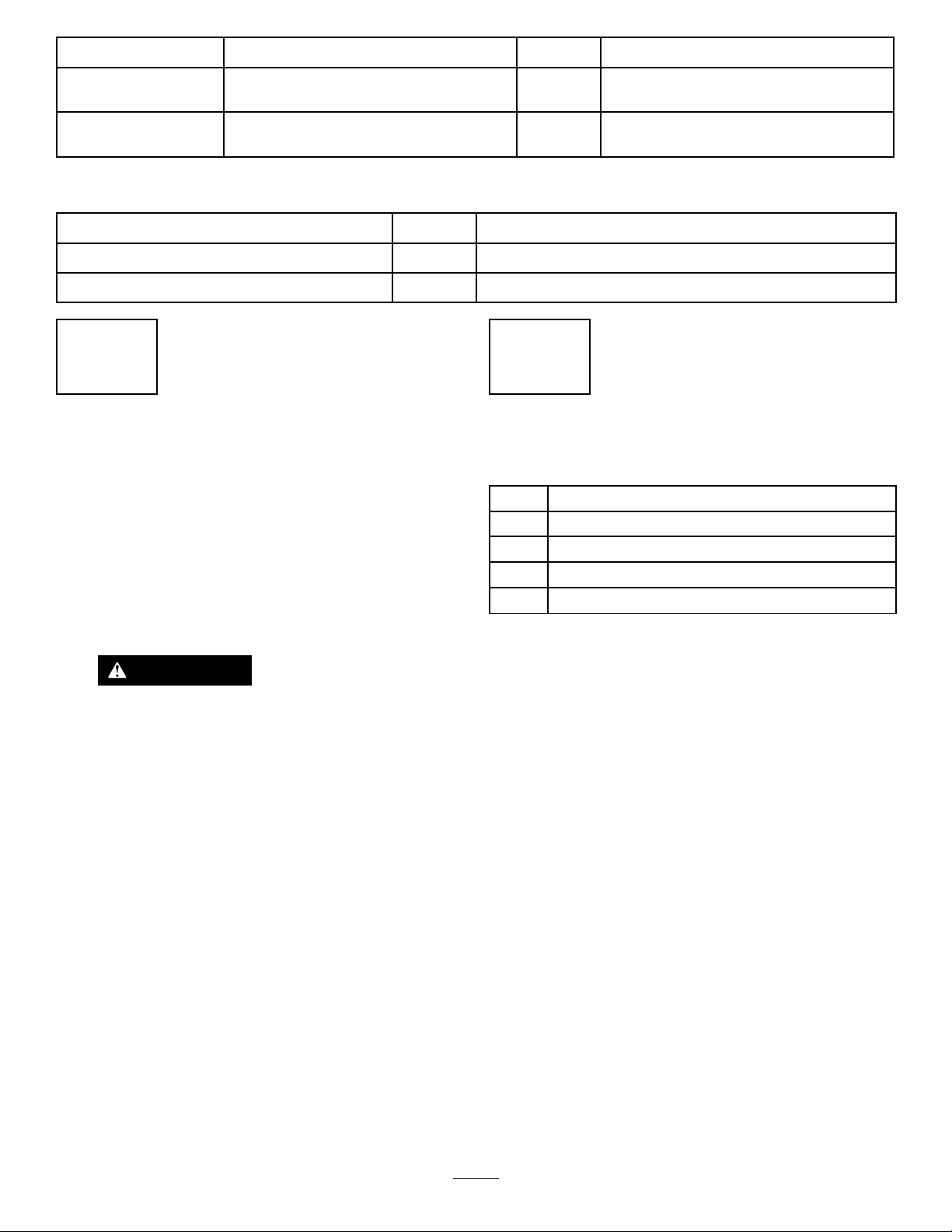
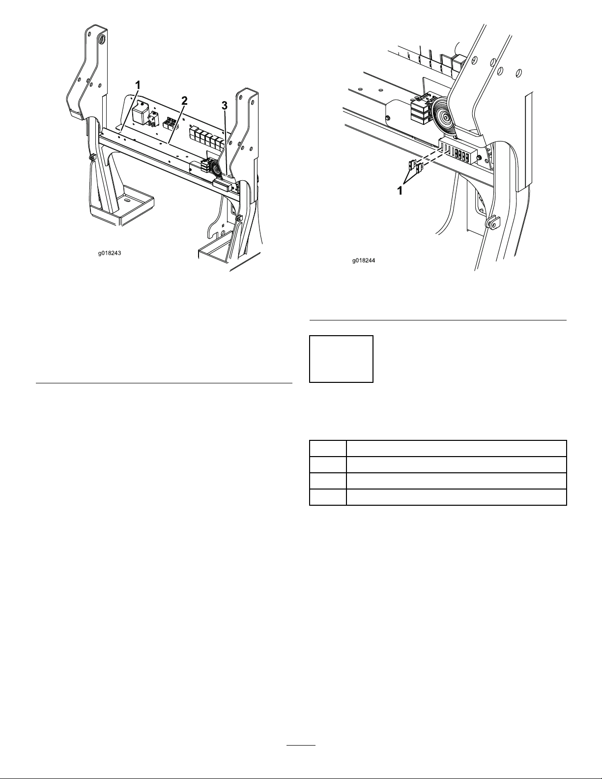
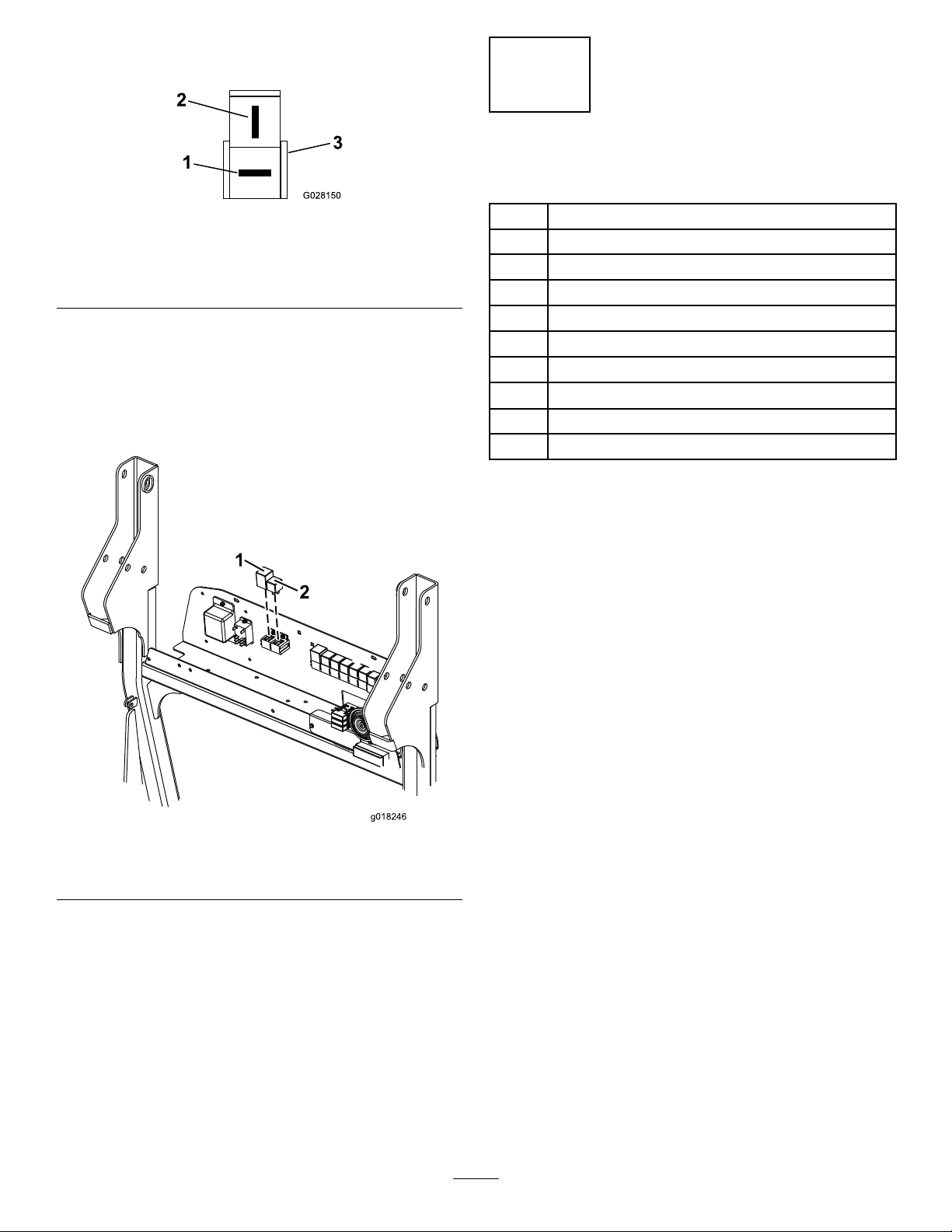
11.Feedallelectricalcablesdownthefrontoftherollbar
frameandontotheelectricalmountpanel.
12.Connectthecablestothemainwiringharnessofthe
machinewhichislocatedontheelectricalbulkhead
(Figure6),asfollows:
A.Connectthe4-pin,left,rear,light-assembly,wiring
connectortothecorresponding4-pinelectrical
connectorontheleftsideofthemainwiring
harness.
B.Connectthe4-pin,right,rear,light-assembly,
wiringconnectortothecorresponding4-pin
electricalconnectorontherightsideofthemain
wiringharness.
Note:The2-pinelectricalconnectorsontheleft
andrightrear-lightassemblyisrequiredforthe
number-platelight.Only1ofthe2-pinelectrical
connectorsisused.
4

g018243
1
23
g018243
Figure6
1.4-pin,left,rear,
light-assemblyconnector
onthemainwiringharness
3.4-pin,left,rear,
light-assemblyconnector
onthemainwiringharness
2.3-pin,
electrical-pressure-switch,
cableconnectoronthe
mainwiringharness
13.Install2fuses(15A)intothefuseblock.Usetherst
andthirdreceptaclesfromtheleftendofthefuse
block(Figure7).
g018244
1
g018244
Figure7
1.Fuse—15amp(2)
3
InstallingthePressureSwitch
Partsneededforthisprocedure:
1Dowtyseal(1/4inch)
1Pressureswitchadapter
1Pressureswitch
1Pressureswitchcable
Procedure
Thepressureswitchcontrolsthebrakelights.Theswitchis
screwedintothemaintransmissionline.
1.Locatethe3hoseconnectionsontherightsideofthe
transmissionpump.Thelowerfrontconnectiontothe
pumphasateettingwithablankingcap.
2.Removethisblankingcapfromtheteetting.
3.Screwthepressureswitchadapterintotheteetting
usingadowtyseal(1/4inch)asshowninFigure8.
5

g018247
123
g018247
Figure8
1.Dowtyseal(1/4inch)3.Pressureswitch
2.Pressure-switchadapter
4.Screwthepressureswitchintothisadapter(Figure8).
Torquetheswitchto34N∙m(25ft-lb).
5.Workingontheelectricalbulkhead,plugthe3-pin
connectoroftheelectricalpressureswitchcabletothe
correspondingconnectorlocatedonthemainwiring
harnessofthemachine(Figure6andFigure9).
g028149
Figure9
Connectorsasviewedfromthecableentryside
1.Green/Yellow5.Blue
2.Yellow6.Pressureswitchconnector
(mainwiringharness)
3.Black7.Pressureswitchcable
connector
4.Brown
6.Runtheelectricalpressureswitchcablefromthe
electricalbulkhead,downtherightrollbarpost,and
forwardalongthechassisrailtothepressureswitch.
7.Plugtheconnectorintothepressureswitchandsecure
it.
4
InstallingtheNumberPlate
Bracket
Partsneededforthisprocedure:
1Numberplatebracket
12-waytabhousingconnector
1Flasherrelay
1Standardshorterrelay
Procedure
Thenumberplatewithlightattachestothebulkhead.
1.Inthecenteroftheplasticbulkheadcover,
approximately40mm(1-1/2inches)fromthefront,
drillan8mmdiameterhole(Figure10).
g018245
1
2
g018245
Figure10
1.Drillahole(8mm)here.2.Numberplatebracket
WARNING
Usingadrillwithoutpropereyeprotection
mayallowdebristoentertheeye,causing
injury.
Whendrillingorcarryingoutotheroperation,
alwaysweareyeprotection.
2.Feedthenumberplatecablethroughthehole(8mm)
intheplasticbulkheadcover.Installthenumberplate
bracketandthebulkheadwiththebulkheadfasteners
previouslyremoved.
6

3.Pushthe2-waytabhousingconnectorontothe
terminalsofthenumberplatecable(Figure11).
g028150
Figure11
1.Redwire3.2-waytabhousing
connector
2.Blackwire
4.Connectthenumber-plate-lightwiringtoeitherthe
leftorrightrear-light-assembly-wiring,2-pinelectrical
connector.
5.Plugtheasherrelayintotheleftvacant-relaysocket
andthestandardshorterrelayintotherightvacant-relay
socket(Figure12).
g018246
1
2
g018246
Figure12
1.Flasherrelay2.Standardshorterrelay
5
InstallingtheFrontLights
Partsneededforthisprocedure:
1Centerheadlightmount
1Rightheadlightmount
1Leftheadlightmount
8Bolt(M6x20mm)
8Locknut(M6)
4Bolt(M10x25mm)
4Locknut(M10)
8Washer(3/8inch)
2Mountingbracket
24-waytabhousingconnector
Procedure
Thefrontlightassembliesattachtothecenterheadlight
mount,whichattachestothemachineusingtwomounting
brackets(Figure13):
1.Installthe2mountingbracketstothefrontofthe
machineusing2bolts(M10x25mm),4washers(3/8
inch),and2locknuts(M10)asshowninFigure13.
2.Installthecenterheadlightmounttothemounting
bracketsusing2bolts(M10x25mm),4washers(3/8
inch),and2locknuts(M10)asshowninFigure13.
3.Applyanti-seizegreasetofullycoattheinsidewallof
thetubeendsandallthesurfacesofthespringsand
tube-endproles(Figure13).
4.Whileholdingtherightheadlightmount,threadthe
wiringcabledownthroughtheendtubesandoutfrom
theheadlightmountcutout(Figure13).
5.Securetherightheadlightmounttothecenterheadlight
mountusingthe4bolts(M6x20mm)and4locknuts
(M6)asshowninFigure13.
7

g018249
9
7
4
8
5
6
1
2
3
4
56
7
8
8
8
10
10
11
g018249
Figure13
1.Centerheadlightmount7.Nylocnut(M10)
2.Rightheadlightmount8.Washer(3/8inch)
3.Leftheadlightmount9.Mountingbracket
4.Screw(M6x20mm)10.Applyanti-seizehere
5.Nylocnut(M6)11.Headlightmountcutout
6.Screw(M10x25mm)
6.Installthe4waytab-housingconnectorontothe
wiringcablebypushingthepinsintothebackof
theconnector.(Figure14).Identifyandmarkthis
connectoras“R”tohelpwithcableidenticationwhen
makingtheconnectionstothemachinemainwiring
harness.
g028151
Figure14
Connectorasviewedfromthecableentryside
1.Blue4.Black
2.Green5.4-waytabhousing
connector
3.Red/White
7.Repeatsteps4through6,markingtheconnectorwith
an“L”instep6.
8.Passthecablesdownthroughthecutoutforthetowing
pointandthoughtheholesinthefrontchassistothe
cuttingunitmanifoldlocatedundertheoperator’s
platform.
9.Locatethetwo4-pinconnectorsonthemainwiring
harnesslocatedneartothecuttermanifold.
10.Connecttheconnectoronthemachinewiringharness
withthegreen/whitewiretotheidentiedleftlight
assemblyconnector.(Figure15).
g028152
Figure15
1.Blue4.Black
2.Green/white5.Green
3.Red/white6.4-waytab-housing
connector
11.Connecttheconnectoronthemachinewiringharness
withthegreen/redwiretotheidentiedrightlight
assemblyconnector(Figure16).
g028152
Figure16
1.Blue4.Black
2.Green/red5.Green
3.Red/white6.4-waytab-housing
connector
8

6
InstallingtheControlPanel
Switches
Partsneededforthisprocedure:
1Instrumentpanelconnectorlead
1Hazardwarningswitch
1Lightsswitch
1Indicatorswitch
1Hornbutton
1Horndecal
24Cabletie
Procedure
1.Removethe6screwssecuringthecontrolpaneltothe
controlpod.
2.Carefullyliftoffthepanel.
Note:Ensurethattheconnectorstotheexisting
switchesarenotdisturbed.
3.Installtheinstrumentpanelconnectorleadintothe
controlarm.
4.Feedtheconnectorleadinstrumentpanelupthrough
theopeninginthebottomofthecontrolpodsothat
theendwiththe3connectorsareinsidethecontrol
pod,andtheendwiththesinglelargeconnectorisfed
downthecontrolarm.
5.RemovetheswitchblankpanelsFigure17.
Note:Thepanelsarelocatedjustabovethekeyswitch
ontherearfaceofthecontrolpod.
g018292
12
g018292
Figure17
1.Switchblank—lightswitch2.Switchblank—hazard
switch
6.Passthehazardandlightswitchconnectorsthrough
theswitchhole.
Note:Thehazardandlightconnectorsareonthe
shorterleads;thehazardconnectorisredandthelight
connectorisblack.Theindicatorconnectorisblack
andonthelongerlead.
7.Connectthelightandhazardswitchestothecorrect
connectorandpushtheswitchintothehole(Figure
18).
g018253
12
g018253
Figure18
1.Lightswitch2.Hazardswitch
9

8.Onthecontrolpanel,removetheroundplug(horn
button)andtherectangularplug(indicatorswitch)
showninFigure19.
G018336
12
g018336
Figure19
1.Roundplug—hornbutton2.Rectangular
plug—indicatorswitch
9.Installthehorndecal;lineitupwiththeedgesofthe
roundandrectangularholes(Figure20).
G018335
1
2
3
g018335
Figure20
1.Hornbutton3.Directionindicatorswitch
2.Horndecal
10.Installthehornbuttonandthedirectionindicator
switchontothecontrolpanel(Figure20).Installthe
directionindicatorswitchwiththegreen/redwires
totheleftandthegreen/whitewirestotheright,as
showninFigure21.
1
2
G018338
g018338
Figure21
1.Green/Red2.Green/White
11.Connectthedirectionindicatorswitchtotheconnector
leadinstrumentpanel.
Note:Theindicatorconnectorisblackandonthe
longerlead.
12.Connectthepinkwireandtheblack/purplewireto
thehornbutton.
Note:Thepinkwireandtheblack/purplewireare
locatedinthecontrolpanel.
13.Workingundertheoperatorplatform,connectthe
connectorleadinstrumentpaneltothemulti-pin
connectoronthemachine’smainelectrical-wiring
harness.
Note:Themulti-pinconnectorislocatedinthe
chassisrailtotherightofthetransmissionpump.
14.Attachcabletiestoallcablesforthefrontlights,rear
lights,andthepressureswitch.
Important:Ensurethatthecabletiesproperly
securethecables.Thetieswillpreventthecables
frombecomingtrappedorchafed.
15.Connectthenegativebatterycable.
16.Testtheswitchesonthecontrolpaneltoensurethat
theyareoperatingcorrectly.
17.Retthecontrolpaneltoensurethatnoconnectors
havebecomedetachedandthatnocablesarenipped.
18.Lowerandlatchtheenginecoverandoperator’s
platform.
10

7
InstallingtheReectors
Partsneededforthisprocedure:
2Reector
Procedure
Afxareectortoeachsideoftheenginecover.Ensure
thattheoutsideedgeofeachreectorisadhered100mm(4
inches)fromeachedgeoftheenginecover(Figure22).
Note:Ensurethatthesurfaceiscleanbeforemountingthe
reectors.
g018255
1
2
g018255
Figure22
1.100mm(4inches)2.Reector
8
InstallingtheSerialLabel
Partsneededforthisprocedure:
1Seriallabel
Procedure
Afxtheseriallabeladjacenttothemachineseriallabel.
Note:Ensurethatthesurfaceiscleanbeforemountingthe
seriallabel.
11

Operation
Specications
Voltage:12V
AdjustingtheHeadlights
UsingthetopscrewsshowninFigure23,adjusttheheadlights
perlocalstandards.
G018337
1
g018337
Figure23
1.Headlightadjustingscrews
OperatingtheLights
LightsSymbols
Thelightscontrolsaremarkedwiththesymbolsshownin
Figure24.
g028277
Figure24
1.Hazardwarning3.Lights—On/Off
2.Directionindicators
PositionMarkerLights(FrontandRear)
Whenyoupressthetopoftheswitch,theswitchilluminates
andthered(rear)andwhite(front)markerlightscomeon.
Headlights
RotatetheignitionswitchtopositionItoilluminatethe
headlights.
HazardLights
Whenyoupressthetopofthehazardlightswitch,all4
indicatorlampsash.Theignitionswitchdoesnotneedto
beonforthesetooperate.
DirectionIndicators
WiththeignitionswitchatpositionI,presstherelevantside
ofthedirectionindicatorswitch.The2indicatorlampson
thatsideofthemachinewillash.
BrakeLights
Thebrakelightsautomaticallyturnonwhenthemachineis
decelerating(whenthecontrolpedalisreturningtoneutral,
whentravellinginaforwarddirectiononly).
Maintenance
GeneralMaintenance
Important:Replaceallwornordamagedpartswith
genuineToroparts.
1.Checkthatalllightsareworkingonaregularbasis.
2.Ensurethattheheadlightsareadjustedcorrectly.
3.Cleanthelightsdaily.
Important:Donotusesolvent-basedproducts,as
theymaydamagethelight.
ReplacingaBulb
1.Removethelenscover.
2.Replacethebulb.
3.Replacethelenscover.
4.Adjustthelights;refertoAdjustingtheHeadlights
(page12).
12

Notes:

DeclarationofIncorporation
TheT oroCompany,8111LyndaleAve.South,Bloomington,MN,USAdeclaresthatthefollowingunit(s)
conform(s)tothedirectiveslisted,wheninstalledinaccordancewiththeaccompanyinginstructionsontocertain
ToromodelsasindicatedontherelevantDeclarationsofConformity.
ModelNo.SerialNo.ProductDescriptionInvoiceDescriptionGeneralDescriptionDirective
02917400000000andUpRoadLightswithBrake
LightsKit
KIT-ROADLIGHTS
W/BRAKELIGHTSGM3400RoadandBrakeLights2004/108/EC
RelevanttechnicaldocumentationhasbeencompiledasrequiredperPartBofAnnexVIIof2006/42/EC.
Wewillundertaketotransmit,inresponsetorequestsbynationalauthorities,relevantinformationonthispartly
completedmachinery.Themethodoftransmissionshallbeelectronictransmittal.
ThismachineryshallnotbeputintoserviceuntilincorporatedintoapprovedT oromodelsasindicatedonthe
associatedDeclarationofConformityandinaccordancewithallinstructions,wherebyitcanbedeclaredin
conformitywithallrelevantDirectives.
Certied:EUTechnicalContact:
MarcelDutrieux
ManagerEuropeanProductIntegrity
ToroEuropeNV
Nijverheidsstraat5
2260Oevel
DavidKlisBelgium
Sr.EngineeringManager
8111LyndaleAve.SouthTel.+3216386659
Bloomington,MN55420,USA
December2,2016

InternationalDistributorList
Distributor:Country:PhoneNumber:Distributor:Country:Phone
Number:
AgrolancKftHungary3627539640MaquiverS.A.Colombia5712364079
BalamaPrimaEngineeringEquip.HongKong85221552163MaruyamaMfg.Co.Inc.Japan81332522285
B-RayCorporationKorea82325512076Mountelda.s.CzechRepublic420255704
220
CascoSalesCompanyPuertoRico7877888383Mountelda.s.Slovakia420255704
220
CeresS.A.CostaRica5062391138MunditolS.A.Argentina54114821
9999
CSSCTurfEquipment(pvt)Ltd.SriLanka94112746100NormaGardenRussia74954116120
CyrilJohnston&Co.NorthernIreland442890813121OslingerTurfEquipmentSAEcuador59342396970
CyrilJohnston&Co.RepublicofIreland442890813121OyHakoGroundandGarden
Ab
Finland35898700733
EquiverMexico525553995444ParklandProductsLtd.NewZealand6433493760
FemcoS.A.Guatemala5024423277PerfettoPoland48618208416
ForGarderOUEstonia3723846060PratoverdeSRL.Italy390499128
128
G.Y .K.CompanyLtd.Japan81726325861Prochaska&CieAustria4312785100
GeomechanikiofAthensGreece30109350054RTCohen2004Ltd.Israel97298617979
GolfinternationalTurizmTurkey902163365993RiversaSpain34952837500
GuandongGoldenStarChina862087651338LelyTurfcareDenmark4566109200
HakoGroundandGardenSweden4635100000SolvertS.A.S.France331308177
00
HakoGroundandGardenNorway4722907760SpyprosStavrinidesLimitedCyprus35722434131
HayterLimited(U.K.)UnitedKingdom441279723444SurgeSystemsIndiaLimitedIndia911292299901
HydroturfInt.CoDubaiUnitedArabEmirates97143479479T-MarktLogisticsLtd.Hungary3626525500
HydroturfEgyptLLCEgypt2025194308ToroAustraliaAustralia61395807355
IrrimacPortugal351212388260ToroEuropeNVBelgium3214562960
IrrigationProductsInt'lPvtLtd.India0091442449
4387
ValtechMorocco21253766
3636
JeanHeybroekb.v.Netherlands31306394611VictusEmakPoland48618238369
EuropeanPrivacyNotice
TheInformationT oroCollects
ToroWarrantyCompany(T oro)respectsyourprivacy.Inordertoprocessyourwarrantyclaimandcontactyouintheeventofaproductrecall,weaskyou
tosharecertainpersonalinformationwithus,eitherdirectlyorthroughyourlocalT orocompanyordealer.
TheT orowarrantysystemishostedonserverslocatedwithintheUnitedStateswhereprivacylawmaynotprovidethesameprotectionasapplies
inyourcountry.
BYSHARINGYOURPERSONALINFORMATIONWITHUS,YOUARECONSENTINGTOTHEPROCESSINGOFYOURPERSONALINFORMATION
ASDESCRIBEDINTHISPRIVACYNOTICE.
TheWayT oroUsesInformation
Toromayuseyourpersonalinformationtoprocesswarrantyclaims,tocontactyouintheeventofaproductrecallandforanyotherpurposewhichwetell
youabout.T oromayshareyourinformationwithToro'safliates,dealersorotherbusinesspartnersinconnectionwithanyoftheseactivities.Wewillnot
sellyourpersonalinformationtoanyothercompany.Wereservetherighttodisclosepersonalinformationinordertocomplywithapplicablelawsand
withrequestsbytheappropriateauthorities,tooperateoursystemsproperlyorforourownprotectionorthatofotherusers.
RetentionofyourPersonalInformation
Wewillkeepyourpersonalinformationaslongasweneeditforthepurposesforwhichitwasoriginallycollectedorforotherlegitimatepurposes
(suchasregulatorycompliance),orasrequiredbyapplicablelaw.
Toro'sCommitmenttoSecurityofYourPersonalInformation
Wetakereasonableprecautionsinordertoprotectthesecurityofyourpersonalinformation.Wealsotakestepstomaintaintheaccuracyandcurrent
statusofpersonalinformation.
AccessandCorrectionofyourPersonalInformation
Ifyouwouldliketorevieworcorrectyourpersonalinformation,pleasecontactusbyemailat[email protected].
AustralianConsumerLaw
AustraliancustomerswillnddetailsrelatingtotheAustralianConsumerLaweitherinsidetheboxoratyourlocalToroDealer.
374-0269RevH

ToroGeneralCommercialProductWarranty
ATwo-YearLimitedWarranty
ConditionsandProductsCovered
TheT oroCompanyanditsafliate,ToroWarrantyCompany,pursuant
toanagreementbetweenthem,jointlywarrantyourT oroCommercial
product(“Product”)tobefreefromdefectsinmaterialsorworkmanship
fortwoyearsor1500operationalhours*,whicheveroccursrst.This
warrantyisapplicabletoallproductswiththeexceptionofAerators
(refertoseparatewarrantystatementsfortheseproducts).Wherea
warrantableconditionexists,wewillrepairtheProductatnocosttoyou
includingdiagnostics,labor,parts,andtransportation.Thiswarranty
beginsonthedatetheProductisdeliveredtotheoriginalretailpurchaser.
*Productequippedwithanhourmeter.
InstructionsforObtainingWarrantyService
YouareresponsiblefornotifyingtheCommercialProductsDistributoror
AuthorizedCommercialProductsDealerfromwhomyoupurchasedthe
Productassoonasyoubelieveawarrantableconditionexists.Ifyouneed
helplocatingaCommercialProductsDistributororAuthorizedDealer,or
ifyouhavequestionsregardingyourwarrantyrightsorresponsibilities,
youmaycontactusat:
ToroCommercialProductsServiceDepartment
ToroWarrantyCompany
8111LyndaleAvenueSouth
Bloomington,MN55420-1196
952–888–8801or800–952–2740
E-mail:[email protected]
OwnerResponsibilities
AstheProductowner,youareresponsibleforrequiredmaintenanceand
adjustmentsstatedinyourOperator'sManual.Failuretoperformrequired
maintenanceandadjustmentscanbegroundsfordisallowingawarranty
claim.
ItemsandConditionsNotCovered
Notallproductfailuresormalfunctionsthatoccurduringthewarranty
periodaredefectsinmaterialsorworkmanship.Thiswarrantydoesnot
coverthefollowing:
•Productfailureswhichresultfromtheuseofnon-T ororeplacement
parts,orfrominstallationanduseofadd-on,ormodiednon-T oro
brandedaccessoriesandproducts.Aseparatewarrantymaybe
providedbythemanufactureroftheseitems.
•Productfailureswhichresultfromfailuretoperformrecommended
maintenanceand/oradjustments.Failuretoproperlymaintainyour
ToroproductpertheRecommendedMaintenancelistedinthe
Operator’sManualcanresultinclaimsforwarrantybeingdenied.
•ProductfailureswhichresultfromoperatingtheProductinanabusive,
negligent,orrecklessmanner.
•Partssubjecttoconsumptionthroughuseunlessfoundtobedefective.
Examplesofpartswhichareconsumed,orusedup,duringnormal
Productoperationinclude,butarenotlimitedto,brakepadsand
linings,clutchlinings,blades,reels,rollersandbearings(sealedor
greasable),bedknives,sparkplugs,castorwheelsandbearings,tires,
lters,belts,andcertainsprayercomponentssuchasdiaphragms,
nozzles,andcheckvalves,etc.
•Failurescausedbyoutsideinuence.Conditionsconsideredtobe
outsideinuenceinclude,butarenotlimitedto,weather,storage
practices,contamination,useofunapprovedfuels,coolants,lubricants,
additives,fertilizers,water,orchemicals,etc.
•Failureorperformanceissuesduetotheuseoffuels(e.g.gasoline,
diesel,orbiodiesel)thatdonotconformtotheirrespectiveindustry
standards.
•Normalnoise,vibration,wearandtear,anddeterioration.
•Normal“wearandtear”includes,butisnotlimitedto,damagetoseats
duetowearorabrasion,wornpaintedsurfaces,scratcheddecalsor
windows,etc.
Parts
Partsscheduledforreplacementasrequiredmaintenancearewarranted
fortheperiodoftimeuptothescheduledreplacementtimeforthatpart.
Partsreplacedunderthiswarrantyarecoveredforthedurationofthe
originalproductwarrantyandbecomethepropertyofToro.Torowillmake
thenaldecisionwhethertorepairanyexistingpartorassemblyorreplace
it.T oromayuseremanufacturedpartsforwarrantyrepairs.
DeepCycleandLithium-IonBatteryWarranty:
DeepcycleandLithium-Ionbatterieshaveaspeciedtotalnumberof
kilowatt-hourstheycandeliverduringtheirlifetime.Operating,recharging,
andmaintenancetechniquescanextendorreducetotalbatterylife.Asthe
batteriesinthisproductareconsumed,theamountofusefulworkbetween
chargingintervalswillslowlydecreaseuntilthebatteryiscompletelyworn
out.Replacementofwornoutbatteries,duetonormalconsumption,
istheresponsibilityoftheproductowner.Batteryreplacementmaybe
requiredduringthenormalproductwarrantyperiodatowner’sexpense.
Note:(Lithium-Ionbatteryonly):ALithium-Ionbatteryhasapartonly
proratedwarrantybeginningyear3throughyear5basedonthetime
inserviceandkilowatthoursused.RefertotheOperator'sManualfor
additionalinformation.
MaintenanceisatOwner’sExpense
Enginetune-up,lubrication,cleaningandpolishing,replacementoflters,
coolant,andcompletingrecommendedmaintenancearesomeofthe
normalservicesT oroproductsrequirethatareattheowner’sexpense.
GeneralConditions
RepairbyanAuthorizedToroDistributororDealerisyoursoleremedy
underthiswarranty.
NeitherTheToroCompanynorToroWarrantyCompanyisliablefor
indirect,incidentalorconsequentialdamagesinconnectionwiththe
useoftheToroProductscoveredbythiswarranty,includingany
costorexpenseofprovidingsubstituteequipmentorserviceduring
reasonableperiodsofmalfunctionornon-usependingcompletion
ofrepairsunderthiswarranty.ExceptfortheEmissionswarranty
referencedbelow,ifapplicable,thereisnootherexpresswarranty.All
impliedwarrantiesofmerchantabilityandtnessforusearelimitedto
thedurationofthisexpresswarranty.
Somestatesdonotallowexclusionsofincidentalorconsequential
damages,orlimitationsonhowlonganimpliedwarrantylasts,sotheabove
exclusionsandlimitationsmaynotapplytoyou.Thiswarrantygivesyou
speciclegalrights,andyoumayalsohaveotherrightswhichvaryfrom
statetostate.
Noteregardingenginewarranty:
TheEmissionsControlSystemonyourProductmaybecoveredby
aseparatewarrantymeetingrequirementsestablishedbytheU.S.
EnvironmentalProtectionAgency(EPA)and/ortheCaliforniaAirResources
Board(CARB).Thehourlimitationssetforthabovedonotapplytothe
EmissionsControlSystemWarranty.RefertotheEngineEmissionControl
WarrantyStatementsuppliedwithyourproductorcontainedintheengine
manufacturer’sdocumentationfordetails
CountriesOtherthantheUnitedStatesorCanada
CustomerswhohavepurchasedT oroproductsexportedfromtheUnitedStatesorCanadashouldcontacttheirToroDistributor(Dealer)toobtain
guaranteepoliciesforyourcountry,province,orstate.IfforanyreasonyouaredissatisedwithyourDistributor'sserviceorhavedifcultyobtaining
guaranteeinformation,contacttheT oroimporter.374-0253RevC
Other manuals for 02917
1
This manual suits for next models
1
Table of contents
Other Toro Lawn Mower Accessories manuals

Toro
Toro Reelmaster 5510 User manual

Toro
Toro 144-0380 User manual

Toro
Toro 98-2671 User manual

Toro
Toro 134-3722 User manual

Toro
Toro 145-3530 User manual

Toro
Toro Recycler Kit 131-4184 User manual

Toro
Toro 04063 User manual

Toro
Toro Z Master 500 Series User manual

Toro
Toro 133-0170 User manual

Toro
Toro Greensmaster eFlex 1018 User manual