Toro 31200 User manual

FormNo.3409-974RevB
Groundsmaster®3602-Wheel
Drive,4-WheelDrive,or4-Wheel
DrivewithCabMulti-Purpose
Machine
ModelNo.31200—SerialNo.400000000andUp
ModelNo.31202—SerialNo.400000000andUp
ModelNo.31203—SerialNo.400000000andUp
Registeratwww.Toro.com.
OriginalInstructions(EN)*3409-974*B

WARNING
CALIFORNIA
Proposition65Warning
Thisproductcontainsachemical
orchemicalsknowntotheStateof
Californiatocausecancer,birthdefects,
orreproductiveharm.
Dieselengineexhaustandsomeofits
constituentsareknowntotheStateof
Californiatocausecancer,birthdefects,
andotherreproductiveharm.
GenuineT orosparkarrestersareapprovedbythe
USDAForestryService.
ItisaviolationofCaliforniaPublicResourceCode
Section4442or4443touseoroperatetheengineon
anyforest-covered,brush-covered,orgrass-covered
landunlesstheengineisequippedwithaspark
arrester,asdenedinSection4442,maintainedin
effectiveworkingorderortheengineisconstructed,
equipped,andmaintainedforthepreventionofre.
Introduction
Thismachineisaride-on,multi-purposemachine
intendedtobeusedbyprofessional,hiredoperators
incommercialapplications.Itisprimarilydesignedfor
maintaininggrassonwell-maintainedlawnsinparks,
sportselds,andoncommercialgrounds.Itisnot
designedforcuttingbrush,mowinggrassandother
growthalongsidehighways,orforagriculturaluses.
Readthisinformationcarefullytolearnhowtooperate
andmaintainyourproductproperlyandtoavoid
injuryandproductdamage.Youareresponsiblefor
operatingtheproductproperlyandsafely.
YoumaycontactTorodirectlyatwww.T oro.com
forproductsafetyandoperationtrainingmaterials,
accessoryinformation,helpndingadealer,orto
registeryourproduct.
Wheneveryouneedservice,genuineT oroparts,or
additionalinformation,contactanAuthorizedService
DealerorT oroCustomerServiceandhavethemodel
andserialnumbersofyourproductready.Figure1
identiesthelocationofthemodelandserialnumbers
ontheproduct.Writethenumbersinthespace
provided.
g014165
Figure1
1.Modelandserialnumberlocation
ModelNo.
SerialNo.
Thismanualidentiespotentialhazardsandhas
safetymessagesidentiedbythesafety-alertsymbol
(Figure2),whichsignalsahazardthatmaycause
seriousinjuryordeathifyoudonotfollowthe
recommendedprecautions.
g000502
Figure2
1.Safety-alertsymbol
Thismanualalsouses2wordstohighlightinformation.
Importantcallsattentiontospecialmechanical
informationandNoteemphasizesgeneralinformation
worthyofspecialattention.
©2017—TheToro®Company
8111LyndaleAvenueSouth
Bloomington,MN554202
Contactusatwww.Toro.com.
PrintedintheUSA
AllRightsReserved

Contents
Safety.......................................................................4
GeneralSafety...................................................4
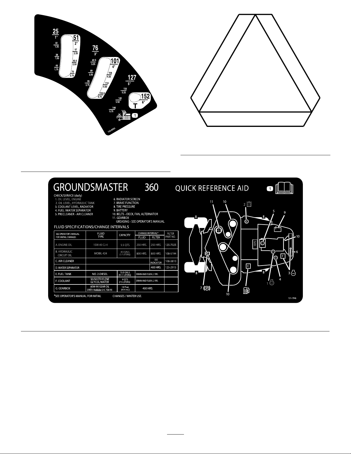
SafetyandInstructionalDecals..........................4
Setup.......................................................................11
1InstallingthePTODriveshafttoanOptional
MowerDeckorQAS.......................................11
2UsingtheOptionalMower-Deck-Mounting
Hardware......................................................12
3AdjustingtheRollBar.....................................12
4CheckingtheTirePressure............................13
5CheckingtheFluidLevels..............................13
ProductOverview...................................................14
Controls...........................................................14
CabControls.................................................15
Specications..................................................20
Attachments/Accessories.................................21
BeforeOperation.................................................21
BeforeOperationSafety...................................21
AddingFuel......................................................22
CheckingtheEngine-OilLevel..........................23
CheckingtheCoolingSystem...........................23
CheckingtheHydraulicSystem........................23
ThinkSafetyFirst..............................................23
UsingtheSafety-InterlockSystem....................23
PositioningtheStandardSeat..........................24
RaisingandLoweringtheSeat.........................25
DuringOperation.................................................26
DuringOperationSafety...................................26
UsingtheRollover-ProtectionSystem
(ROPS)—2-WheelDrivewithROPS
and4-WheelDrivewithROPSModels
Only..............................................................27
StartingandShuttingOfftheEngine.................28
DrivingtheMachine..........................................28
StoppingtheMachine.......................................29
SelectingtheSteeringMode.............................29
OperatingtheMower........................................29
AdjustingtheHeightofCut...............................30
CuttingGrasswiththeMachine........................30
DieselParticulateFilterRegeneration...............31
OperatingTips.................................................39
AfterOperation....................................................40
AfterOperationSafety......................................40
PushingtheMachinebyHand..........................40
HaulingtheMachine.........................................40
LocatingtheTie-DownPoints...........................41
Maintenance...........................................................42
RecommendedMaintenanceSchedule(s)...........42
DailyMaintenanceChecklist.............................43
Pre-MaintenanceProcedures..............................44
Pre-MaintenanceSafety...................................44
PreparingtheMachineforMaintenance............45
UsingtheHood-PropRod.................................45
Lubrication..........................................................46
GreasingtheBearingsandBushings................46
EngineMaintenance...........................................48
EngineSafety...................................................48
ServicingtheAirCleaner..................................48
ServicingtheEngineOil....................................49
ServicingtheDiesel-OxidationCatalyst
(DOC)andtheSootFilter..............................50
FuelSystemMaintenance...................................51
ServicingtheWaterSeparator..........................51
ServicingtheEngineFuelFilter........................52
CheckingtheFuelLinesand
Connections..................................................52
CleaningtheFuelPick-UpTubeScreen............52
ElectricalSystemMaintenance...........................52
ElectricalSystemSafety...................................52
CheckingtheFuses..........................................52
ServicingtheBattery.........................................53
StoringtheBattery............................................53
DriveSystemMaintenance..................................54
CheckingtheTirePressure...............................54
CorrectingSteeringMisalignment.....................54
CoolingSystemMaintenance..............................55
CoolingSystemSafety.....................................55
CheckingtheCoolingSystem..........................55
CleaningtheRadiator.......................................56
BrakeMaintenance.............................................57
AdjustingtheServiceBrakes............................57
AdjustingtheParkingBrake..............................57
BeltMaintenance................................................58
CheckingtheAlternatorBelt.............................58
ControlsSystemMaintenance.............................58
AdjustingtheTractionDriveforNeutral.............58
AdjustingtheMaximumGroundSpeed.............59
HydraulicSystemMaintenance...........................60
HydraulicSystemSafety...................................60
CheckingtheHydraulicSystem........................60
ChangingtheHydraulicFluidAnd
Filter..............................................................61
CabMaintenance.................................................62
FillingtheWasher-FluidBottle..........................62
CleaningtheCabAirFilters..............................62
CleaningtheAir-ConditioningCoil....................63
Cleaning..............................................................64
CleaningtheCab..............................................64
DisposingofWaste...........................................64
Storage...................................................................64
PreparingtheEngine........................................64
PreparingtheMachine......................................64
3

Safety
Thismachinehasbeendesignedinaccordancewith
ENISO5395:2013andANSIB71.4-2012.
GeneralSafety
Thisproductiscapableofamputatinghandsand
feetandofthrowingobjects.Alwaysfollowallsafety
instructionstoavoidseriouspersonalinjury.
Usingthisproductforpurposesotherthanitsintended
usecouldprovedangeroustoyouandbystanders.
•Readandunderstandthecontentsofthis
Operator’sManualbeforestartingtheengine.
•Donotputyourhandsorfeetnearmoving
componentsofthemachine.
•Donotoperatethemachinewithoutallguards
andothersafetyprotectivedevicesinplaceand
workingonthemachine.
•Keepclearofanydischargeopening.Keep
bystandersandpetsasafedistanceawayfrom
themachine.
•Keepchildrenoutoftheoperatingarea.Never
allowchildrentooperatethemachine.
•Stopthemachineandshutofftheenginebefore
servicing,fueling,oruncloggingthemachine.
Improperlyusingormaintainingthismachinecan
resultininjury.T oreducethepotentialforinjury,
complywiththesesafetyinstructionsandalwayspay
attentiontothesafety-alertsymbol,whichmeans
Caution,Warning,orDanger—personalsafety
instruction.Failuretocomplywiththeseinstructions
mayresultinpersonalinjuryordeath.
Youcanndadditionalsafetyinformationwhere
neededthroughoutthisOperator’sManual.
SafetyandInstructionalDecals
Safetydecalsandinstructionsareeasilyvisibletotheoperatorandarelocatednearanyarea
ofpotentialdanger.Replaceanydecalthatisdamagedormissing.
decal93-6696
93-6696
1.Storedenergyhazard—readtheOperator'sManual.
decal117-4979
117-4979
1.Rotatingbelt—keepguardinplace.
decal117-3276
117-3276
1.Enginecoolantunder
pressure
3.Warning—donottouchthe
hotsurface.
2.Explosionhazard—read
theOperator'sManual.
4.Warning—readthe
Operator'sManual.
4

decal117-3270
117-3270
1.Warning—donottouchthehotsurface.
2.Cutting/dismembermenthazard,hand;entanglement
hazard,belt—stayawayfrommovingparts;keepallguards
andshieldsinplace.
decal117-3272
117-3272
1.Warning—readtheOperator'sManual;failuretousethe
rolloverprotectionsystem(ROPS)canresultininjuryinthe
eventofarollover;wearaseatbeltwhenarollbarisin
place,donotwearaseatbeltwhentherollbarislowered.
decal106-2353
106-2353
1.Electricalpowerpoint
decal117-4766
117-4766
1.Cutting/dismembermenthazard;fan—stayawayfrom
movingparts;keepallguardsandshieldsinplace.
decal98-4387
98-4387
1.Warning—wearhearingprotection.
decal120-6604
120-6604
1.Thrownobjecthazard—keepbystandersawayfromthe
machine.
2.Cutting/dismembermenthazardofhand,mower
blade—stayawayfrommovingparts;keepallguardsand
shieldsinplace.
3.Cutting/dismembermenthazardoffoot,mowerblade—stay
awayfrommovingparts;keepallguardsandshieldsin
place.
5

decal107-2908
107-2908
1.Thrownobjecthazard—keepbystandersasafedistance
awayfromthemachine.
2.Thrownobjecthazard—donotoperatethemowerwiththe
deectoruporremoved;keepthedeectorinplace.
3.Cutting/dismembermenthazardofhandorfoot,mower
blade—stayawayfrommovingparts.
decal106-9206
106-9206
1.Wheeltorquespecications
2.ReadtheOperator'sManual.
decal117-3233
117-3233
1.ReadtheOperator'sManualforinformationonfuses.
2.4-wheelsteersolenoid(7.5A)
3.PTOenable,4-wheel-steerlamp,decklift,deckoat(7.5A)
4.Glowindicator,fuel-runsolenoid,diagnosticlight,start(7.5
A)
5.Headlights,deckactuator,powertakeoff(10A)
6.Lights(15A)
7.Operator-presenceswitch(10A)
8.Powerpoint,lights(15A)
9.Engine(10A)
decal117-2718
117-2718
decalbatterysymbols
BatterySymbols
Someorallofthesesymbolsareonyourbattery.
1.Explosionhazard6.Keepbystandersasafe
distanceawayfromthe
battery.
2.Nore,opename,or
smoking
7.Weareyeprotection;
explosivegasescan
causeblindnessandother
injuries.
3.Causticliquid/chemical
burnhazard
8.Batteryacidcancause
blindnessorsevereburns.
4.Weareyeprotection.9.Flusheyesimmediately
withwaterandgetmedical
helpfast.
5.ReadtheOperator's
Manual.
10.Containslead;donot
discard.
6

decal117-3273
117-3273
1.Warning—readtheOperator'sManual.6.Thrownobjecthazard—keepbystandersasafedistance
awayfromthemachine.
2.Warning—donotoperatethismachineunlessyouaretrained.7.Warning—engagetheparkingbrake,shutofftheengine,
andremovethekeyfromthekeyswitchbeforeleavingthe
machine.
3.Warning—weartheseatbeltwhenseatedintheoperator's
position.
8.Tippinghazard—lowerthecuttingunitwhendrivingdown
slopes;slowthemachinebeforeturning,donotturnathigh
speeds.
4.Cutting/dismembermenthazardofhandorfoot—removethe
keyfromthekeyswitchandreadtheinstructionsbefore
servicingorperformingmaintenance.
9.Cuttinghazardofhandorfoot—stayawayfrommovingparts;
keepallguardsinplace.
5.Warning—wearhearingprotection.
decal107-2916
107-2916
1.Removethekeyfromthekeyswitch
andreadtheOperator'sManualbefore
servicingorperformingmaintenance.
2.Thrownobjecthazard—donotoperate
themowerwiththedeectorupor
removed;keepthedeectorinplace;
keepbystandersasafedistanceaway
fromthemachine.
3.Cutting/dismembermenthazardof
handorfoot,mowerblade—stayaway
frommovingparts.
decal125-4399
125-4399
1.Lowerthedeck4.Slow7.Engine—start
2.Raisethedeck5.Engine—shutoff8.2-wheelsteering
3.Fast6.Engine—run9.4-wheelsteering
7

decal121-8378
121-8378
ModelwithCabOnly
1.Fan—off5.Externalair
2.Fan—onfull6.Internalair
3.Coldair7.Airconditioner—off
4.Hotair8.Airconditioner—on
0
0
0
0
0
0
0
0
00000
00000
00000
00000
00000
00000
00000
00000
00000
00000
00000
00000
00000
00000
00000
00000
00000
00000
0000
0000
0000
000
00
00
000000
000000
000000
000000
000000
000000
000000
00
00
decal125-9248
125–9248
ModelwithCabOnly
1.Raise/Lowerdecks5.Fast
2.Engine—stop6.Slow
3.Engine—run7.2-wheelsteering
4.Engine—start8.4–wheelsteering
8

decal132-3600
132-3600
ModelwithCabOnly
1.ReadtheOperator's
Manualformore
informationonfuses.
5.Workinglight(20A)
2.Headlight(25A)6.Auxiliarypower(15A)
3.CondenserfanandA/C
clutch(30A)
7.Cablight(15A)
4.Fan(25A)8.Windshieldwipers(15A)
decal125-9688
125-9688
ModelwithCabOnly
1.Windshieldwipers—off3.Windshieldwipers—on
2.Windshieldwipers4.Spraywindshieldwasher
uid
decal130-0611
130-0611
ModelwithCabOnly
1.Warning—1)Removethepin;2)Raisethedoors;3)Exit
thecab
decal130-0594
130-0594
ModelwithCabOnly
1.Warning—readtheOperator’sManual;whensittinginthe
cab,alwayswearaseatbelt;wearhearingprotection.
decal132-6552
132-6552
2-WheelDrivewithROPSand4-WheelDrivewithROPS
ModelsOnly
1.Heightofcut
9

decal132-6553
132-6553
ModelwithCabOnly
1.Heightofcut
decal120-0250
120-0250
1.Slow-movingvehicle
decal131-1946
131–1946
1.ReadtheOperator’sManualformoreinformationonservicingthemachine.
10

Setup
LooseParts
Usethechartbelowtoverifythatallpartshavebeenshipped.
ProcedureDescriptionQty.Use
PTOdriveshaft1
Bolt(5/16x1-3/4inches)4
Locknut(5/16inch)4
1Rollpin(3/16x1-1/2inches)2
InstallthePTOdriveshafttoaoptional
deckorQAS.
Retainerpin2
Greasetting2
2Washerheadscrew(5/16x7/8inch)2
Usethehardwaretoinstalltheoptional
mowerdeck.
3Nopartsrequired–Adjusttherollbar.
4Nopartsrequired–Checkthetirepressure.
5Nopartsrequired–Checkthelevelsofthehydraulicuid,
engineoil,andcoolant.
MediaandAdditionalParts
DescriptionQty.Use
Operator'sManual1Readthemanualbeforeoperatingthemachine.
Engineowner'smanual1Readthemanualbeforeoperatingthemachine.
PartsCatalog1UsethePartsCatalogtoreferencepartnumbers.
Operatortrainingmaterial1Reviewbeforeoperatingmachine
1
InstallingthePTO
DriveshafttoanOptional
MowerDeckorQAS
Partsneededforthisprocedure:
1PTOdriveshaft
4Bolt(5/16x1-3/4inches)
4Locknut(5/16inch)
2Rollpin(3/16x1-1/2inches)
Procedure
Note:InstallingthePTOdriveshaftiseasierifyou
positionthemachineonahoist.
1.Parkthemachineonalevelsurface,engagethe
parkingbrake,shutofftheengine,andremove
thekeyfromthekeyswitch.
WARNING
Donotstarttheengineandengagethe
PTOswitchwhenthePTOdriveshaftis
disconnectedfromthecuttingdeck.If
youstarttheengineandthePTOshaft
isallowedtorotate,seriouspersonal
injuryandmachinedamagecould
result.BeforethePTOdriveshaftis
disconnectedfromthecuttingdeck,
disconnectthePTOsolenoid-valve-coil
connectorfromthewireharnessto
preventunintentionallyengagingthe
PTOclutch.
2.Disconnectthewire-harnessconnectorfromthe
PTOsolenoid-valve-coilconnector(Figure3).
11

G018339
1
g018339
Figure3
1.Wire-harnessconnector
3.PositionthePTOdriveshaftunderthefrontofthe
machine.Ensurethattheslip-shaftyokeofthe
driveshaftispositionedtowardthetransmission
driveshaft(Figure4).
G018340
1
2
3
4
5
g018340
Figure4
1.Transmissiondriveshaft4.Locknut
2.Bolt5.Rollpin
3.PTOdriveshaft
4.Alignthesplineandroll-pinholeofthedriveshaft
yokewiththetransmissiondriveshaft.
5.SlidethePTOdriveshaftendyokeontothe
transmissiondriveshaft.
6.SecuretheendyokeofthePTOdriveshaftas
follows:
A.Installtherollpinintheendyokeandshaft.
B.Installtheboltsthroughthedriveshaftend
yoke.
C.Installandtightenthelocknutstosecurethe
endyoketothePTOdriveshaft.
Note:Retaintheremainingbolts,locknuts,
androllpintosecuretheotherendofthe
driveshafttotheattachmentgearboxshaft.
D.Torquethelocknutsto20to25N-m(175
to225in-lb).
7.LubricatethegreasettingsonthePTO
driveshaft.
8.Afteryouconnecttheotherendofthedriveshaft
totheattachmentgearboxshaft,connect
thewire-harnessconnectortothePTO
solenoid-valve-coilconnector(Figure3).
2
UsingtheOptional
Mower-Deck-Mounting
Hardware
Partsneededforthisprocedure:
2Retainerpin
2Greasetting
2Washerheadscrew(5/16x7/8inch)
Procedure
Note:Thesecomponentsandprocedurearerequired
onlyifamowerdeckthatrequiresretainerpinsis
mountedtothetractionunit.Refertothemowerdeck
Operator’sManualfortheinstallationinstructions.
Note:Ifyouarenotinstallingamowerdeckonthe
tractionunit,removeortieupthe4deck-liftchains
fromtheliftsuspension.
3
AdjustingtheRollBar
NoPartsRequired
Procedure
1.Removethehairpincottersandthepinsfrom
therollbar(Figure5).
2.Raisetherollbartotheuprightpositionand
installthe2pinsandsecurethemwiththe
hairpincotters(Figure5).
Note:Ifyoumustlowertherollbar,pushthebar
forwardtorelievepressureonthepins,remove
thepins,lowerthebarslowly,andsecureitwith
thepinssothatitdoesnotdamagethehood.
12

Donotweartheseatbeltwhentherollbaris
foldeddown.
g014166
Figure5
1.Rollbar3.Hairpincotter
2.Pin
4
CheckingtheTirePressure
NoPartsRequired
Procedure
Thetiresareoverinatedforshipping.Therefore,
releasesomeoftheairtoreducethepressure.Check
thetirepressure;refertoCheckingtheTirePressure
(page54).
5
CheckingtheFluidLevels
NoPartsRequired
Procedure
1.Checkthelevelofthehydraulicuidbefore
startingtheengine;refertoCheckingthe
HydraulicSystem(page60).
2.Checktheleveloftheengineoilbeforestarting
theengine;refertoCheckingtheEngine-Oil
Level(page49).
3.Checkthecoolingsystembeforestartingthe
engine;refertoCheckingtheCoolingSystem
(page55).
13

ProductOverview
Controls
Becomefamiliarwithallthecontrolsbeforeyoustart
theengineandoperatethemachine.
TractionPedal
Thetractionpedal(Figure6)controlstheforwardand
reverseoperation.Pressthetopofthepedaltomove
forwardandthebottomtomoverearward.Theground
speeddependsonhowfaryoupressthepedal.For
noload,maximumgroundspeed,fullypressthepedal
whilethethrottleisintheFASTposition.
Tostopthemachine,reducethefootpressureon
thetractionpedalandallowittoreturntothecenter
position.
g197397
Figure6
1.Parkingbrake3.Tilt-steeringpedal
2.Brakepedal4.Tractionpedal
BrakePedal
Usethebrakepedalwiththebrake-pedallatchto
engageanddisengagetheparkingbrake(Figure
6).Tostopthemachine,releasethetractionpedal
andallowittoreturntothecenterposition.Youcan
usethebraketoassistinstoppingthemachineinan
emergencysituation.
ParkingBrake
Toengagetheparkingbrake,pushdownonthebrake
pedalandpressthetopforwardtolatchit(Figure
6).T odisengagetheparkingbrake,pressthebrake
pedaluntiltheparking-brakelatchretracts.
Tilt-SteeringPedal
Totiltthesteeringwheeltowardyou,pressthefoot
pedaldownandpullthesteeringtowertowardyouto
themostcomfortablepositionandthenreleasethe
pedal(Figure6).
Engine-SpeedSwitch
Theengine-speedswitch(Figure7)has2modesto
changetheenginespeed.Bymomentarilytapping
theswitch,youcanincreaseordecreasetheengine
speedinincrementsof100rpm.Pressandholdthe
switchtosettheenginespeeddirectlytohighorlow
idle,dependingonwhichendoftheswitchyoupress.
2
G026098
1
567
43
g026098
Figure7
1.InfoCenter5.Powerpoint
2.Power-takeoff(PTO)
switch
6.Keyswitch
3.Engine-speedswitch7.Deck-liftswitch
4.Steeringselectorswitch
InfoCenter
TheInfoCenterLCDdisplayshowstheoperating
status,variousdiagnostics,andotherinformation
aboutthemachine(Figure7).
KeySwitch
Thekeyswitchhas3positions:OFF,ON/PREHEAT,
andSTART(Figure7).
Power-Takeoff(PTO)Switch
Thepower-takeoff(PTO)switchstartsandstopsthe
attachment(Figure7).
SteeringSelectorSwitch
4-WheelDriveMachinesOnly
Pressthesteeringselectorswitchtotherearto
engage4-wheelsteeringandforwardtoreturnto
2-wheelsteering(Figure7).
14

PowerPoint
Thepowerpointprovidesa12Vpowersupplyfor
electronicdevices(Figure7).
Important:Ifthemowerdeckshutsdownand
theInfoCentertemperature-warningiconison,
pushthePTOknobdown;drivetoasafe,at
area;movethethrottlelevertotheSLOWposition;
allowthetractionpedaltomovetotheNEUTRAL
position;andengagetheparkingbrake.Allowthe
enginetoidleforseveralminuteswhileitcoolsto
asafelevel.Shutofftheengineandcheckthe
coolingsystem;refertoCheckingtheCooling
System(page55).
FuelGauge
Thefuelgauge(Figure8)indicatesthefuellevel
remaininginthefueltank.
g014170
Figure8
1.Fuelgauge2.Fuel-tankcap
CabControls
ModelwithCabOnly
g198816
Figure9
1.Fancontrol4.Air-conditioningswitch
2.Temperaturecontrol5.Air-recirculationcontrol
3.Windshield-wiperswitch
Air-RecirculationControl
Setsthecabtoeitherrecirculatetheairinthecabinor
todrawairintothecabinfromoutside(Figure9).
•Setittorecirculatetheairwhenusingthe
air-conditioning.
•Setittodrawairinwhenusingtheheaterorfan.
Fan-ControlKnob
Rotatethefan-controlknobtoregulatethespeedof
thefan(Figure9).
Temperature-Control-Knob
Rotatethetemperature-controlknobtoregulatethe
airtemperatureinthecab(Figure9).
Windshield-WiperSwitch
Usethisswitchtoturnthewindshieldwipersonor
off(Figure9).
Air-ConditioningSwitch
Usethisswitchtoturntheairconditioningonoroff
(Figure9).
WindshieldLatch
Liftupthelatchtoopenthewindshield(Figure10).
Pressinthelatchtolockthewindshieldintheopen
position.Pulloutanddownonthelatchtocloseand
securethewindshield.
15

g196911
Figure10
1.Windshieldlatch
RearWindowLatch
Liftupthelatchestoopentherearwindow.Pressin
thelatchtolockthewindowintheopenposition.Pull
outanddownonthelatchtocloseandsecurethe
window(Figure10).
Important:Youmustclosetherearwindow
beforeopeningthehood;otherwise,damagemay
occur.
UsingtheInfoCenterLCDDisplay
TheInfoCenterLCDdisplayshowsinformationabout
yourmachine,suchastheoperatingstatus,various
diagnostics,andotherinformationaboutthemachine
(Figure11).Thereisasplashscreenandmain
informationscreenoftheInfoCenter.Youcanswitch
betweenthesplashscreenandmaininformation
screenatanytimebypressinganyoftheInfoCenter
buttonsandthenselectingtheappropriatedirectional
arrow.
1
g020650
2
3
4
TORO
g020650
Figure11
1.Indicatorlight3.Middlebutton
2.Rightbutton4.Leftbutton
•Leftbutton,menuaccess/backbutton—press
thisbuttontoaccesstheInfoCentermenus.You
canuseittobackoutofanymenuthatyouare
currentlyusing.
•Middlebutton—usethisbuttontoscrolldown
menus.
•Rightbutton—usethisbuttontoopenamenu
wherearightarrowindicatesadditionalcontent.
Note:Thepurposeofeachbuttonmaychange
dependingonwhatisrequiredatthetime.Each
buttonislabeledwithanicondisplayingitscurrent
function.
16

InfoCenterIconDescription
SERVICEDUEIndicateswhenscheduledservice
shouldbeperformed
Enginerpm/status—indicatesthe
enginerpm
Hourmeter
Infoicon
Fast
Slow
Stationaryregenerationrequired
Glowplugsareactive
AC
2-wheelsteer
4-wheelsteer
Operatormustsitinseat
Parkingbrakeindicator—indicates
whentheparkingbrakeisset
CoolantT emperature-indicatesthe
enginecoolanttemperatureineither
°Cor°F
Temperature(hot)
PTOisengaged
Deniedornotallowed
Enginestart
Stoporshutdown
Engine
Keyswitch
PINcode
CANbus
InfoCenterIconDescription(cont'd.)
InfoCenter
Badorfailed
Bulb
OutputofTECcontrollerorcontrol
wireinharness
Switch
Operatormustreleaseswitch
Operatorshouldchangetoindicated
state
Symbolsareoften
combinedtoform
sentences.Some
examplesareshown
below
Operatorshouldputmachinein
Neutral
Enginestartdenied
Engineshutdown
Enginecoolanttoohot
DPFashaccumulation
notication.RefertoServicing
theDiesel-OxidationCatalyst(DOC)
andtheSootFilter(page50)for
details.
or
Sitdownorengageparkingbrake
UsingtheMenus
ToaccesstheInfoCentermenusystem,pressthe
menuaccessbuttonwhileatthemainscreen.This
bringsyoutothemainmenu.Refertothefollowing
tablesforasynopsisoftheoptionsavailablefrom
themenus:
MainMenu
MenuItemDescription
17

FaultsTheFaultsmenucontains
alistoftherecentmachine
faults.RefertotheService
ManualoryourAuthorized
ToroDistributorformore
informationontheFaults
menuandtheinformation
containedthere.
ServiceTheServicemenucontains
informationonthemachine
suchashoursofusecounters
andothersimilarnumbers.
DiagnosticsTheDiagnosticsmenu
displaysthestateofeach
machineswitch,sensorand
controloutput.Youcanuse
thistotroubleshootcertain
issuesasitwillquicklytellyou
whichmachinecontrolsareon
andwhichareoff.
SettingsTheSettingsmenuallows
youtocustomizeandmodify
congurationvariablesonthe
InfoCenterdisplay.
AboutTheAboutmenuliststhe
modelnumber,serialnumber,
andsoftwareversionofyour
machine.
Service
MenuItemDescription
HoursListsthetotalnumberofhours
thatthemachine,engine,and
PTOhavebeenon,aswell
asthenumberofhoursthe
machinehasbeentransported
andservicedue
CountsListsnumerouscountsthe
machinehasexperienced
Diagnostics
MenuItemDescription
PTOIndicatestheinputs,qualiers,
andoutputsforenablingthe
PTOcircuit
EngineRunIndicatestheinputs,qualiers,
andoutputsforstartingthe
engine
DecksIndicatestheinputs,qualiers,
andoutputsforliftingand
loweringthedeck
SteerModeIndicatestheinputs,qualiers,
andoutputsforswitching
between2-wheelsteerand
4-wheelsteer
MachineInputIndicatesthestateofother
machineinputssuchas
accessoriesandA/Cclutch
Settings
MenuItemDescription
UnitsControlstheunitsusedonthe
InfoCenter;Themenuchoices
areEnglishorMetric.
LanguageControlsthelanguageused
ontheInfoCenter*
LCDBacklightControlsthebrightnessofthe
LCDdisplay
LCDContrastControlsthecontrastofthe
LCDdisplay
ProtectedMenusAllowsapersonauthorized
byyourcompanywiththe
PINcodetoaccessprotected
menus.
AutoIdleControlstheamountoftime
allowedbeforereturningthe
enginetolowidlewhenthe
machineisstationary
Onlyoperator-facedtextistranslated.Faults,Service,
andDiagnosticsscreensareservice-faced.Thetitles
areintheselectedlanguage,butthemenuitemsare
inEnglish.
About
MenuItemDescription
ModelListsthemodelnumberofthe
machine
SNListstheserialnumberofthe
machine
MachineControllerRevisionListsthesoftwarerevisionof
themastercontroller
InfoCenterRevisionListsthesoftwarerevisionof
theInfoCenter
CANBusListsthemachine
communicationbusstatus
ProtectedMenus
Thereare2operatingcongurationsettingsthatare
adjustablewithintheSettingsMenuoftheInfoCenter:
AutoIdletimedelayandStationaryRegeneration;
refertoDieselParticulateFilterRegeneration(page
31).Youcanlockthesesettingsbyusingthe
ProtectedMenu.
Note:Atthetimeofdelivery,theinitialpassword
codeisprogrammedbyyourdistributor.
AccessingProtectedMenus
Note:ThefactorydefaultPINcodeforyoumachine
iseither0000or1234.
IfyouchangedthePINcodeandforgotthe
code,contactyourAuthorizedToroDistributorfor
assistance.
18

1.FromtheMAINMENU,usethecenterbuttonto
scrolldowntotheSETTINGSMENUandpressthe
rightbutton(Figure12).
g028523
Figure12
2.IntheSETTINGSMENU,usethecenterbuttonto
scrolldowntothePROTECTEDMENUandpress
therightbutton(Figure13A).
g028522
Figure13
3.ToenterthePINcode,pressthecenterbutton
untilthecorrectrstdigitappears,thenpress
therightbuttontomoveontothenextdigit
(Figure13BandFigure13C).Repeatthisstep
untilthelastdigitisenteredandpresstheright
buttononcemore.
4.PressthemiddlebuttontoenterthePINcode
(Figure13D).
WaituntiltheredindicatorlightoftheInfoCenter
illuminates.
Note:IftheInfoCenteracceptsthePINcode
andtheprotectedmenuisunlocked,theword
“PIN”displaysintheupperrightcornerofthe
screen.
Note:RotatethekeyswitchtotheOFFpositionand
thentotheONpositionlockstheprotectedmenu.
Youhavetheabilitytoviewandchangethesettingsin
theProtectedMenu.OnceyouaccesstheProtected
Menu,scrolldowntoProtectSettingsoption.Usethe
rightbuttontochangethesetting.SettingtheProtect
SettingstoOFFallowsyoutoviewandchangethe
settingsintheProtectedMenuwithoutenteringthe
PINcode.SettingtheProtectSettingstoONhidesthe
protectedoptionsandrequiresyoutoenterthePIN
codetochangethesettingintheProtectedMenu.
AfteryousetthePINcode,rotatethekeyswitchOFF
andbacktotheONpositiontoenableandsavethis
feature.
SettingtheAutoIdle
•IntheSettingsMenu,scrolldowntoAutoIdle.
•PresstherightbuttontochangetheAutoIdletime
betweenOFF,8S,10S,15S,20S,and30S.
19

Specications
Note:Specicationsanddesignaresubjecttochangewithoutnotice.
g198083
Figure14
DescriptionFigure14
Reference
DimensionorWeight
HeightwithrollbarupC202cm(80inches)
HeightwithrollbardownG140cm(55inches)
HeightwithcabD225cm(88-1/2inches)
OveralllengthF276cm(108-1/2inches)
OverallwidthB138cm(54inches)
WheelbaseE155cm(61inches)
Wheeltread(tirecentertocenter)rearA112cm(44inches)
Groundclearance15cm(6inches)
20
Other manuals for 31200
1
This manual suits for next models
2
Table of contents
Other Toro Lawn Mower Accessories manuals

Toro
Toro Wheel Horse 78305 User manual

Toro
Toro 120-6950 User manual

Toro
Toro 78479 User manual

Toro
Toro 78514 User manual

Toro
Toro 117-2723 User manual

Toro
Toro 30124 User manual

Toro
Toro 136-5850 User manual

Toro
Toro 140-1559 User manual

Toro
Toro Greensmaster eFlex 1018 User manual

Toro
Toro Flex-Force Power System 51810T User manual