Figure5
1.Cabletie2.Blankingcap
5.Removethe1/4-inchhosefromtheteeonthelift
cylinderfortheright,rearcutting-unit(Figure6).
Figure6
1.1/4-inchhose
6.Attachthenew1/4-inchhosetotheliftcylinder
(Figure6).
7.Loosenthecabletiesandttingonthecenter-back
cutting-unitdrain-hose.
8.Attachthe3/8-inchhosefromthefrontteeassembly
tothebottomoftherearteeassembly(Figure4).
9.Attachtheendofthe1/4-inchhosefromthecenter,
rearcutting-unittotherearteeassembly(Figure4).
10.Attachtheendofthenew1/4-inchhosefromtheright,
rearcutting-unittotherearteeassembly(Figure4).
11.Attachthestraightendofthenew3/8-inchhosetothe
topoftherearteeassembly(Figure4).
12.Tightenallthettingsandthepreviouslyloosened
cableties.
3
InstallingtheFillerPlate
Assembly
Partsneededforthisprocedure:
1Fillerplate
13/8-inchbulkheadtting
1Cabletie
Procedure
1.Removetheoldllerplateassemblyfromthetopof
thetank.
2.Removethellercapassemblyfromtheoldllerplate
andinstallitonthenewllerplate.
Note:Foreaseofinstallation,orientthellerplateso
thatthesmallholeisinthelowerrightcorner(Figure
7).
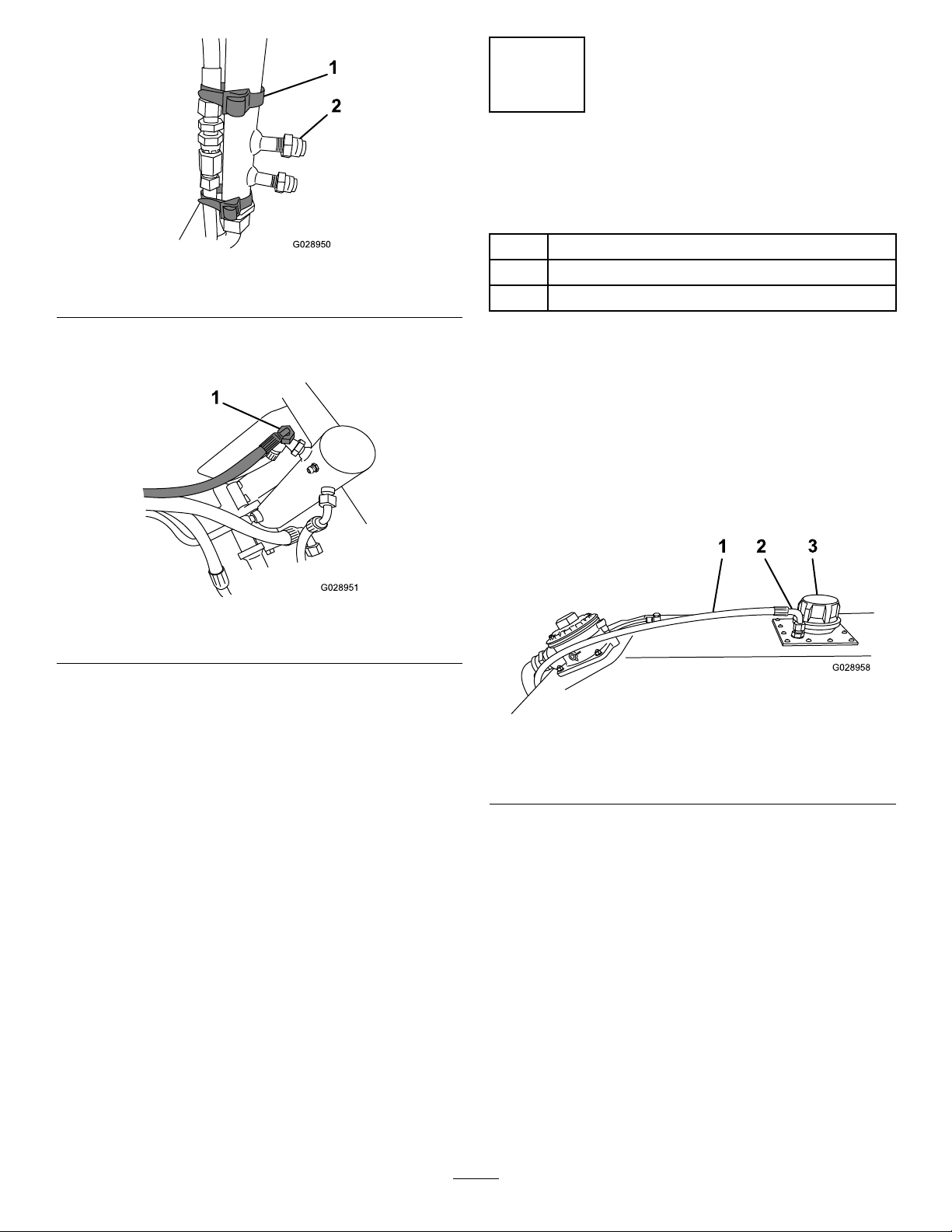
Figure7
1.3/8-inchhose3.Fillercap
2.Bulkheadtting
3.Insertthe3/8-inchbulkheadttingintothellerplate
withthelonglegintothetank(Figure7).
4.Attachthenewllerplateassemblytothetopofthe
oiltankusingthehardwarefromtheoldllerplate.
Note:Ensurethatthebulkheadttingisontheright
whenviewedfromtherearofthemachine.
5.Routethe3/8-inchhosefromtherearteeassembly
uptherightsideofthereturnlterandconnectitto
thebulkheadtting.
6.Securethehosetotherearmanifoldnearthereturn
lterusingacabletie.
3