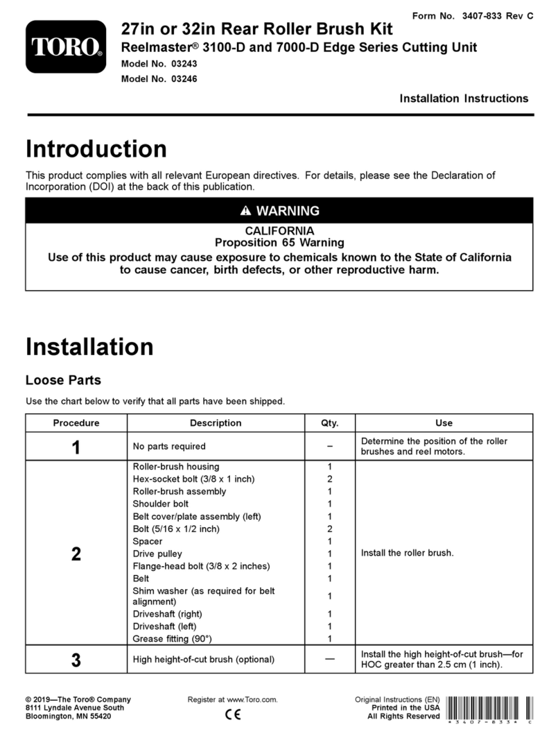
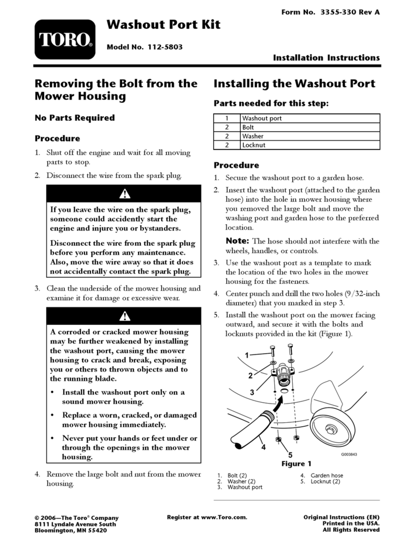
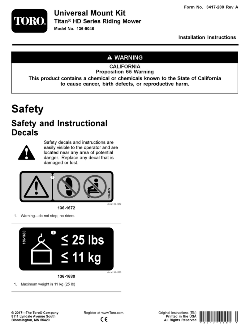
Toro Groundsmaster 4500-D User manual

FormNo.3453-292RevA
RoadLightKit
Groundsmaster®4500-Dor4700-DTractionUnit
ModelNo.30670
InstallationInstructions
Safety
SafetyandInstructionalDecals
Safetydecalsandinstructionsareeasilyvisibletotheoperatorandarelocatednearanyareaof
potentialdanger.Replaceanydecalthatisdamagedormissing.
decal140-1531
140-1531
1.Snowchute—left4.Hazardlight—off
2.Snowchute—right5.Attachment—down
3.Hazardlight—on6.Attachment—up
decal140-1623
140-1623
1.Beacon—off2.Beacon—on
©2022—TheToro®Company
8111LyndaleAvenueSouth
Bloomington,MN55420
Registeratwww.T oro.com.OriginalInstructions(EN)
PrintedintheUSA
AllRightsReserved*3453-292*

decal145-5256
145-5256
1.Power—10A5.ElectricSeat—10A
2.Infocenter—2A6.Engine—10A
3.AuxiliaryPower—10A7.Sensor—10A
4.Headlights—10A8.Cab—60A
2

Installation
LooseParts
Usethechartbelowtoverifythatallpartshavebeenshipped.
ProcedureDescriptionQty.Use
1Nopartsrequired–Preparethemachine.
2Nopartsrequired–Drillthemountingholes.
Rightheadlightbracket1
Leftheadlightbracket1
Bolt(3/8x2-1/2inches)6
Flangenut(3/8inch)6
Washer(3/8x7/8inches)8
Rubberhanger2
Spacer4
Bolt(5/16x1-5/8inches)4
Flangenut(5/16inch)4
Rightheadlightassembly1
Leftheadlightassembly1
3
Bent-platebracket2
Installtheheadlights.
Horn1
Hornbracket1
Bolt(3/8x5/8inch)1
Flangenut(3/8inch)1
Bolt(1/4x2inches)2
4
Nut(1/4inch)2
Installthehorn.
Leftlightbracket1
Rightlightbracket1
Leftlighthousing1
Rightlighthousing1
Innermount2
Screw(#10x1-1/4inches)4
Flangenut(1/4inch)6
Carriagebolt(1/4x5/8inches)2
Screw(1/4x3/4inches)8
Screw(5/8x3inches)4
Flatwasher4
Jamnut(5/8inch)2
Rear-lightassembly2
5
Clipnut(1/4inch)2
Installtherearlamps.
Platelight1
Platebracket1
Screw(#10x1inch)2
Speednut(#10)2
6
Self-tappingscrew(5/16x1/2inch)2
Installthelicense-platebracket.
Wireharness1
Magneticcable-tiemounts2
7Cabletie8
Installthewireharness.
3

ProcedureDescriptionQty.Use
Switchmountassembly1
Controlcover1
Fusemountplate1
Clipnut(#10)3
Flasher1
Flangeheadscrew(#10x3/8inch)1
Cabletie1
Bracketmount2
Clipnut(1/4inch)8
Switchmount1
Multi-functionswitch1
Switchclip(thick)1
Switchclip(thin)1
Switchplug3
Rockerswitch1
Knob2
Fusecover1
Boltretainer2
Carriagebolt(1/4x2inches)4
Flangelocknuts4
Cableties2
Push-infastener2
8
Flange-headsscrew(1/4x3/4inch)6
Installthecontrolconsole.
Fuse(2A)1
9Fusedecal1Installthedecal.
Plate2
Decal4
Hex-headscrew(1/4x2-1/2inches)4
10Locknut(1/4inch)4
Installthedecal-mountingplates.
1
PreparingtheMachine
NoPartsRequired
Procedure
1.Parkthemachineonalevelsuface.
2.DisengagethePTOandengagetheparking
brake.
3.Lowerthecuttingunits.
4.Shutofftheengineandremovethekey.
5.Disconnectthenegative(-)batterycable.
2
DrillingtheMountingHoles
NoPartsRequired
DrillingtheHolesforthe
HeadlightsandtheWireHarness
1.Removethenutsfromthe2carriagebolts
securingtheheadlightstothetraction-unitframe
(Figure1).
2.Removethe2self-tappingboltssecuringthetop
oftheplatformshroudtotheframe(Figure1).
3.Unplugtheheadlightconnectorsandremove
theplatformshroudfromtheframe(Figure1).
4

5.UsingthedimensionsinFigure3,locateand
drill6holes(1.0cm)throughbothwallsofthe
roller-supporttube.
g371868
Figure3
1.6.4cm(2-1/2inches)4.1.0cm(13/32inch)diameter
2.8.9cm(3-1/2inches)5.1.9cm(3/4inch)
3.14.0cm(5-1/2inches)
DrillingtheHolesfortheHorn
Bracket
UsingthedimensionsinFigure4,locateand
drill2holes(9/32inch)throughbothwallsofthe
roller-supporttube.
g029796
Figure4
1.1.9cm(3/4inch)3.25.4cm(10inches)
2.3.8cm(1-1/2inches)4.7mm(9/32inch)diameter
6

DrillingtheMountingHolesinthe
RearBumperfortheLicensePlate
UsingthedimensionsshowninFigure5,locateand
drill2holes(9/32inch)throughtheoutsidewallofthe
rearbumper.
g371179
Figure5
1.8.3cm(3-1/3inches)3.52.07cm(20-1/2inches)
2.13.3cm(5-1/4inches)4.Drillahole(9/32inch)
here.
3
InstallingtheHeadlights
Partsneededforthisprocedure:
1Rightheadlightbracket
1Leftheadlightbracket
6Bolt(3/8x2-1/2inches)
6Flangenut(3/8inch)
8Washer(3/8x7/8inches)
2Rubberhanger
4Spacer
4Bolt(5/16x1-5/8inches)
4Flangenut(5/16inch)
1Rightheadlightassembly
1Leftheadlightassembly
2Bent-platebracket
InstallingtheHeadlightBracketto
aROPSModel
1.Fastentheleftandrightheadlightbracketsto
thefrontoftheroller-supporttubewith6bolts
(3/8x2-1/2inches)and6angenuts(3/8inch)
asshowninFigure6.
g029788
Figure6
1.Installedheadlightbracket3.Headlightbracket
2.Bolts(3/8x2-1/2inches)4.Flangenuts(3/8inch)
Note:Positiontheboltssothattheangenuts
aretowardthefrontofthetractionunit.
2.Fastentheleftandrightheadlightstothe
headlightbrackets(Figure7)withthefasteners
suppliedwiththelights.
7

Note:Ensurethattheturn-signallensonthe
headlightispositionedtowardtheoutsideofthe
tractionunit.
g371180
Figure7
Rightheadlightassemblyshown
1.Headlight4.Pivotbracket
2.Pivotboltwithlocknut5.Washer
3.Mountingbolt6.Locknut(M12)
3.Tightenthelocknuttormlyholdtheheadlight
assemblytotheheadlightbracket.
Note:Donotovertightenthelocknut.
InstallingtheHeadlightBracketto
aCabModel
1.Installabent-platebracketontoeachofthe
uppercornersofthelowerfrontpanelofthecab
withtheexistingscrewsasshowninFigure8.
g034337
Figure8
1.Bolt(5/16x1-5/8inches)5.Rubberhanger
2.Washer6.Flangenut(5/16inch)
3.Bent-platebracket7.Screw(existing)
4.Spacer
2.Looselyinstallarubberhangertoeach
bent-platebracketwithabolt(5/16x1-5/8inch),
2washers(3/8inch),aspacer,andaangenut
(5/16inch)asshowninFigure8.
3.Looselyinstalltheleftandrightheadlight
bracketstothefrontoftheroller-supporttube
with6bolts(3/8x2-1/2inches)andangenuts
(3/8inch).Positionthebracketsasshownin
Figure9.
Note:Ensurethattheholesinthebent-plate
bracketsalignwiththeholesintherubber
hangers.
8

g034338
Figure9
1.Nut(5/16inch)4.Headlightbracket
2.Washer5.Brackettab
3.Spacer6.Bolt(5/16x1-5/8inch)
4.Fastentheleftandrightheadlightassemblies
totheheadlightbrackets(Figure7)withthe
fastenerssuppliedinthekit.
Note:Ensurethattheturn-signallensonthe
headlightispositionedtowardtheoutsideofthe
tractionunit.
5.Tightenthelocknuttormlyholdtheheadlight
assemblytotheheadlight-assemblybracket.
Note:Donotovertightenthelocknut.
Note:Youcannotusethefrontandrearcablightsfor
CEapplications.Disablethefrontandrearcablights
asfollows:
•Front—Removethelightsfromthecabroofand
disconnectthewiresfromthelights.Installthe
lightsintothecab.
•Rear—Removethescrewssecuringthelensesto
thelights.Removethebulbsfromthelightsand
installthelensestothelights.
4
InstallingtheHorn
Partsneededforthisprocedure:
1Horn
1Hornbracket
1Bolt(3/8x5/8inch)
1Flangenut(3/8inch)
2Bolt(1/4x2inches)
2Nut(1/4inch)
Procedure
1.Securethehornstraptothehornbracketwitha
bolt(3/8x5/8inch)andaangenut(3/8inch)
asshowninFigure10.
g371386
Figure10
1.Bolt(1/4x2inches)4.Hornwithstrap
2.Hornbracket5.Flangenut(3/8inch)
3.Nut(1/4inch)6.Bolt(3/8x5/8inch)
2.Mountthehornbrackettothebacksideofthe
roller-supporttubewith2bolts(1/4x2inches)
andnuts(1/4inch).Rotatethehornsothatit
facesdown(Figure10).
9

5
InstallingtheRearLamps
Partsneededforthisprocedure:
1Leftlightbracket
1Rightlightbracket
1Leftlighthousing
1Rightlighthousing
2Innermount
4Screw(#10x1-1/4inches)
6Flangenut(1/4inch)
2Carriagebolt(1/4x5/8inches)
8Screw(1/4x3/4inches)
4Screw(5/8x3inches)
4Flatwasher
2Jamnut(5/8inch)
2Rear-lightassembly
2Clipnut(1/4inch)
Procedure
1.Removethe2bolts,2atwashers,and2jam
nutsconnectedtotheleftandrightframerails.
2.Securetheleftandrightlightbrackettothe
framewith2bolts(5/8x3inches),2atwashers
and2jamnuts(5/8inch)asshownin(Figure
11andFigure12).
Note:Theleftandrightlightbracketsare
different.Ensurethatyouusethecorrectmount.
3.Securetheleftandrightlighthousingstothe
leftandrightlightbracketswith4carriagebolts
(5/8x3inches)and4angenut(1/4inch)as
shownin(Figure12).
Note:Theleftandrightlightbracketsare
different.Ensurethatyouusethecorrectmount.
g371674
Figure11
1.Leftlight2.Rightlight
g371653
Figure12
Leftsideshown
1.Leftlightbracket7.Screw(1/4x3/4inches)
2.Screw(1/4x3/4inches)8.Carriagebolt(1/4x5/8
inches)
3.Innermount9.Leftlighthousing
4.Rearlamp10.Screw(5/8x3inches)
5.Screw(#10x1-1/4inches)11.Flatwasher
6.Leftlighthousing12.Jamnut(5/8inch)
4.Assemblethe2clipnuts(1/4inch)totheinner
mount(Figure13).
10

g371870
Figure13
1.Innermount2.Clipnut(1/4inch)
Note:Afterroutingthewireharnessthroughthe
lightbrackets,mounttherear-lightassembliesto
innermountswith4screws(#10x1-1/4inches)
andnutsincludedwiththelight(Figure25).
6
InstallingtheLicense-Plate
Bracket
Partsneededforthisprocedure:
1Platelight
1Platebracket
2Screw(#10x1inch)
2Speednut(#10)
2Self-tappingscrew(5/16x1/2inch)
Procedure
1.Securetheplatelighttothelicense-platebracket
with2screws(#10x1inch)and2locknuts
(Figure14andFigure15).
Note:Donotovertightenthescrews.Ensure
thatthelenspointsdownwardandthewiresare
insertedthroughtheholeinthelicense-plate
bracket.
g371733
Figure14
1.Speednut(#10)3.Screw(#10x1inch)
2.Platelight
g371652
Figure15
1.Speednut(#10)4.Screw(#10x1inch)
2.License-platebracket5.Self-tappingscrew(5/16x
1/2inch)
3.Platelight
2.Mountthelicense-platebrackettotherear
bumperwith2self-tappingscrews(5/16x1/2
inch)asshowninFigure15.
11

7
InstallingtheWireHarness
Partsneededforthisprocedure:
1Wireharness
2Magneticcable-tiemounts
8Cabletie
Procedure
Usethefollowinginstructionsandillustrationstorouteandconnectthewireharness.Whenroutingthelight
harness,followthemainmachineharness.
g371786
Figure16
1.Removetheange-headscrewsecuringthe
compartmentclampandsealtothetractionunit
(Figure17).
Note:Removetheclampandsealtogain
accesstothefusecompartment.
12

g023198
Figure17
1.Compartmentclamp2.Seal
2.Removetherelays,fuseblock,groundingblock,
andfuseclipfromthesteelplateinthefuse
compartmentnexttothebattery(Figure18).
g371793
Figure18
1.Battery4.Fuseclip
2.Relays5.Moduleinstalled
3.Groundingblock6.Fuseblock
3.Removetheboltsholdingthesteelplateinthe
fusecompartment.
4.Locatethemoduleonthewireharness(Figure
19).
Important:Whenroutingthewireharness,
donotpullitacrosssharpedges,whichmay
damagethewires.Wiresmustnotcontact
hotormovingparts.Securethewireharness
withcableties.
5.Routethewholewireharnessthroughthe
newsteelplateandtheholelocatedatthe
compartmentclamp(Figure17andFigure19).
Routethewireharnessuntilthemodulecontacts
thesteelplate.
g371430
Figure19
1.Bolt(#8x1/2inch)5.Newsteelplate
2.Bracket6.Connectorsfromfuse
block
3.Connectoronthebottom
ofmodule
7.Moduleintheharness
4.Existingbolt8.Bolt(#8x1/2inch)
13

6.Installthenewsteelplateintothefuse
compartmentwiththepreviouslyremovedbolts.
7.Connectthelarge-ringterminal,fromthewire
harness,tothestudonthejunctionblock(Figure
20).
8.Connectthesmall-ringterminalfromthewire
harnessto1ofthescrewsontheground-block
terminal(Figure20).
g371732
Figure20
1.Battery3.Small-ringterminal
2.Large-ringterminal
9.Installthemoduletothesteelplatewiththe
bracketand2bolts(#8x1/2inch);referto
Figure19.
Note:Donotovertightenthescrews.
10.Installthecompartmentclampandsealtothe
tractionunitwiththeange-headscrew(Figure
17).
11.Routethefrontendofthewireharnessunder
theoperatorplatformtothefrontofthetraction
unit(Figure21).
g371712
Figure21
1.Rightfront-light
conncector
4.Brakeconnector
2.Connectorsforthecontrols5.Hornconnectors
3.Leftfront-lightconncector
12.Threadeachharnessconnectorthroughthe
appropriateheadlightbracketandconnectitto
theheadlight(Figure21).
13.Plugthewireharnesslead,withthe2
connectors,intothehorn(Figure22).
g371794
Figure22
1.Horn3.Cabletie
2.Connectors
14.Positiontheplatformshroudontopoftheframe
(Figure23).
15.Securetheshroudandtheheadlightstothe
framewiththe2carriageboltsandnutsyou
previouslyremoved(Figure23).
14

g371181
Figure23
1.Platformshroud4.Self-tappingbolt(2)
2.Headlightassembly5.Createanotchhere.
3.Carriagebolt(2)6.Headlightconnector
16.Routethewireharnesstothesteeringcolumn.
Thesteeringcolumnconnectionswillbeinstalled
whenthecontrolconsoleisinstalled.
17.Connectthebrakeconnectortothemain
harnessundertheplatformnearthebrake
connections(Figure21).
18.Routethewireharnesstothebackofthe
machineundertherightsideofthetractionunit
(Figure26).
19.Routetheleftwireconnectorundertotheleft,to
therearlightbracket.
20.Threadeachrearlightconnectorthroughthe
appropriaterearlightbracket(Figure24).
g371711
Figure24
1.Left,rear-lightconnector3.License-plateconnector
2.Right,rear-lightconnector
21.Alignthe4-socketconnectoroftheharness
throughtheinnermount(Figure25).
22.Assembletheinnermountintothelighthousing,
andsecurethemounttothehousing(Figure25)
with4socket-headscrews(1/4x3/4inch).
23.Alignthetaillighttothelighthousingwiththe
yellowlenspositionedasshowninFigure25.
24.Plugthe4-socketconnectoroftheharnessinto
the4-pinconnectorofthetaillight(Figure25).
25.Assemblethetaillightintothelighthousing,and
securethelighttothehousing(Figure25)with2
Phillips-headscrews(#10x1-1/4inches).
g371798
Figure25
1.Socket-headscrew(1/4x
3/4inch)
5.4-socketconnector
(taillightharness)
2.Innermount6.Phillips-headscrew(#10x
1-1/4inches)
3.Yellowlens(taillight)7.Clipnut(#10)
4.Redlens(taillight)
26.Routethewireharnesstothelicense-platelight
andplugthewire-harnessconnectorintothe
lightconnector(Figure24).
Important:Securethewireharnesswith
cabletiessothatitdoesnotcontactanyhot
ormovingparts(Figure26).
15

g371724
Figure26
1.Magneticcable-tiemounts2.Cabletie
27.Installanypartsthatwereremovedfromthe
tractionunittoroutethewireharness.
8
InstallingtheControl
Console
Partsneededforthisprocedure:
1Switchmountassembly
1Controlcover
1Fusemountplate
3Clipnut(#10)
1Flasher
1Flangeheadscrew(#10x3/8inch)
1Cabletie
2Bracketmount
8Clipnut(1/4inch)
1Switchmount
1Multi-functionswitch
1Switchclip(thick)
1Switchclip(thin)
3Switchplug
1Rockerswitch
2Knob
1Fusecover
2Boltretainer
4Carriagebolt(1/4x2inches)
4Flangelocknuts
2Cableties
2Push-infastener
6Flange-headsscrew(1/4x3/4inch)
AssemblingtheFuseMountPlate
1.Aligntheconnectorsforthecontrolsthroughthe
previouslymadenotchintheheadlightassembly
(Figure2).
2.Pullthebootdownandassemblethebottomof
itintothesteeringcover.
3.Assembletheclipnut(#10)ontothefusemount
plate(Figure27).
16

g350763
Figure27
1.Clipnut(#10)4.Flangeheadscrew(#10x
3/8inch)
2.Fusemountplate5.Cabletie
3.Flasher
4.Assembletheashertothemountplate(Figure
27)withaangeheadscrew(#10x3/8inch).
5.Securetheashertothemountplatewitha
cabletie(Figure27).
6.Plugthe12-socketconnectoroftheconsole
harnessintothe12-pinconnectoroftheasher
(Figure28).
g371871
Figure28
1.12-pinconnector(asher)2.12-pinsocket(console
harness)
7.Insertpush-inanchoroftheconsoleharness
intothe6.4mm(1/4inch)holeinthebracket
mount(Figure29).
17

g350766
Figure29
1.Bracketmount2.Push-inanchor(console
harness)
AssemblingtheSwitchMount
1.Assemblethe8clipnut(1/4inch)totheswitch
mountasshowninFigure30.
g350767
Figure30
1.Switchmount2.Clipnut(1/4inch)
2.Insertthemulti-functionswitchintothe51mm
(2inch)holeintheswitchmountasshownin
Figure31.
g350769
Figure31
1.Switchmount2.Multi-functionswitch
18

3.Securethemulti-functionswitchtotheswitch
mountwiththethickandthinswitchclips(Figure
32).
g350778
Figure32
1.Tab(multi-functionswitch)3.Switchclip(thin)
2.Switchclip(thick)
4.Insertthe3switchplugsintotheswitchmount
asshowninFigure33.
g350770
Figure33
1.Switchplug
5.Aligntherockerswitchtotheswitchmountwith
thelensofthelighttothefrontoftheswitch
plate(Figure34).
g350768
Figure34
1.Rockerswitch2.Frontoftheswitchplate
6.Assemblethe2knobsintothefusecover,and
securetheknobswith2boltretainers(Figure
35).
g350764
Figure35
1.Boltretainer3.Knob
2.Fusecover
7.Assemblethefusecovertotheswitchplate,and
tightentheknobs(Figure35).
19

InstallingtheSwitchPlatetothe
SteeringColumn
1.Aligntheswitchplatetotherearwardsideorthe
steeringcolumn(Figure37).
g350762
Figure36
1.Carriagebolt(1/4x2
inches)
2.Bracketmount
2.Attheupper6.4mm(1/4inch)holes,assemble
2carriageboltsbolt(1/4x2inches)throughthe
switchplateandtheotherbracketmount(Figure
36).
3.Assemblethefusemountplatetotheupper
bracketmountandcarriagebolts(Figure37)
with2angelocknuts(1/4inch).
g350772
Figure37
1.Bracketmount4.Fusemountplate
2.Carriagebolt(1/4x2
inches)
5.Flangelocknut(1/4inch)
3.Switchmount
4.Atthelower6.4mm(1/4inch)holes,assemble
2carriageboltsbolt(1/4x2inches)throughthe
switchplate,bracketmount,andfusemount
plate(Figure37)with2carriagebolts(1/4x2
inches)and2angelocknuts(1/4inch).
5.Aligntheswitchplatetotheoperator’sseat,and
tightenthe4angelocknuts.
ConnectingtheConsoleHarness
totheSwitches
1.Plugthe8-socketconnectorofthecontrol
harnesslabeledHAZARDSWITCHintothe8-pin
connectoroftherockerswitch(Figure38).
g350776
Figure38
1.8-pinconnector(rocker
switch)
2.8-socketconnector
(labeledHAZARD
SWITCH—console
harness)
20
Other manuals for Groundsmaster 4500-D
16
This manual suits for next models
2
Table of contents
Other Toro Lawn Mower Accessories manuals
Toro
Toro GrandStand 133-1439 User manual

Toro
Toro Recycler Kit 131-4184 User manual

Toro
Toro GrandStand 133-1434 User manual

Toro
Toro 30215 User manual

Toro
Toro 121-7530 User manual

Toro
Toro 110-2025 User manual

Toro
Toro 161-4519 User manual

Toro
Toro 07320 User manual

Toro
Toro 136-5850 User manual

Toro
Toro Kevlar 02878 User manual