Toro 30640 User manual

FormNo.3392-741RevA
EULightKit
2015andAfterGroundsmaster®3604-WheelDriveMulti-Purpose
MachinewithCab
ModelNo.30640
InstallationInstructions
Installation
LooseParts
Usethechartbelowtoverifythatallpartshavebeenshipped.
ProcedureDescriptionQty.Use
1Nopartsrequired–Prepareforinstallation.
2Nopartsrequired–Installtheoorplateaccesshole.
Columnbracketassembly1
Hornassembly1
Columnbracketmount1
Carriagescrew,3/8inchx1inch2
Flangenut,3/8inch2
Columncover1
3
Screw2
Installtheswitchcolumnassembly.
Rightheadlightassembly1
Leftheadlightassembly1
Flangeheadscrew,3/8x1inch4
Flangenut,3/8inch4
Rightheadlightshield1
Leftheadlightshield1
4
Screw,1/4x5/8inch8
Installtheheadlights.
Hornassembly1
Screw,5/16x3/4inch1
5Flangeheadnut,5/16inch1
Installthehorn.
Leftrearlampassembly1
Rightrearlampassembly1
6Washerheadscrew,3/8x3/4inch4
Installtherearlamps.
Grommet1
Cabletie,7–1/4inch(184mm)13
7Cabletie,14–1/2inch(368mm)2
Connectthewiringharness.
8Nopartsrequired–Finishtheinstallation.
MediaandAdditionalParts
DescriptionQty.Use
Installationinstructions1Usetheseinstructionstoinstallthekit.
Partscatalog1Usethiscatalogtoreferencepartnumbers.
©2014—TheToro®Company
8111LyndaleAvenueSouth
Bloomington,MN55420
Registeratwww.T oro.com.OriginalInstructions(EN)
PrintedintheUSA.
AllRightsReserved*3392-741*A
1
PreparingforInstallation
NoPartsRequired
Procedure
1.Parkthemachineonalevelsurface,stoptheengine,
engagetheparkingbrakeandremovethekeyfromthe
ignitionswitch.
2.Disconnectthenegative(–)batterycablefromthe
battery.
WARNING
Wearsafetygogglesandrubbergloveswhen
workingwithbatteries.Sincethegasesare
explosive,keepopenamesandelectrical
sparkawayfrombatteries.Donotsmoke.
3.Pressthesteeringcolumnpedaldown,pivotthe
steeringtowerforwardasfaraspossibleandthen
releasethepedal
4.Movetheseatlatch,locatedontheleftsideoftheseat,
rearwardtounlatchtheseatandpullforwardonthe
topoftheseatuntiltheseatlatchcatchessupporting
seatplate(Figure1).
Figure1
1.Seatlatch
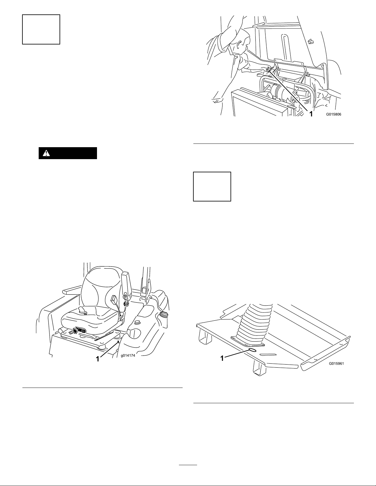
5.Raiseandsecurethehoodasfollows:
•Releasethehoodlatches.
•Liftuponthehooduntiltheproprodcanbe
positionedbehindtheframetube(Figure2).
1G015806
Figure2
1.Proprod
•Lowerthehooduntiltherodisinfrontofand
restingagainsttheframetube.
2
InstallingtheFloorPlate
AccessHole
NoPartsRequired
Procedure
1.Removetheknockoutplug,locatedbetweenthebrake
pedalandthesteeringcolumnintheoorplate(Figure
3).Iftheoorplatedoesnothaveaknockoutplug,
proceedtothenextstepfordrillinginstructions.
G015961
1
Figure3
1.Knockoutpluglocation
2.UsingthedimensionsinFigure4,locate,markanddrill
a2inch(51mm)diameterholeintheoorplate.
Note:Whendrillingthroughtheoorplate,use
cautionnottohitthehydrauliclinedirectlyunderthe
holelocation.
2
3
2
1
G015966
Figure4
1.1inch(25mm)3.1–5/8inches(41mm)
2.2inchdiameter(51mm)
3
InstallingtheSwitchColumn
Assembly
Partsneededforthisprocedure:
1Columnbracketassembly
1Hornassembly
1Columnbracketmount
2Carriagescrew,3/8inchx1inch
2Flangenut,3/8inch
1Columncover
2Screw
Procedure
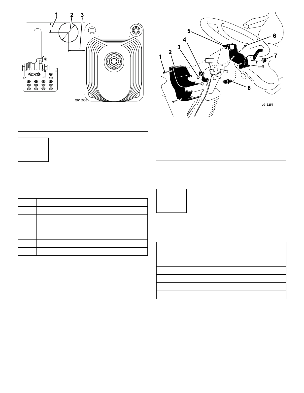
1.Mountthehornswitchtothecolumnbracketwiththe
rubberhornbutton(Figure5).Donotusethesilver
buttonincludedwiththehorn.
2.Mountthecolumnbracketassemblytotherearofthe
steeringcolumnwiththecolumnbracketmount,2
carriagescrews(3/8x1inch),and2angenuts(3/8
inch).
3.Positionthecolumnbracketashighaspossibleonthe
steeringcolumnasshowninFigure5.Makesurethe
columnbracketdoesnotinterferewiththesteering
wheel.
Note:Overtighteningthecarriagescrews/angenuts
maydistortthecolumnbracketprohibitingthecover
frombeinginstalled.
Figure5
1.Screw(2)5.Columnbracketassembly
2.Columncover6.Carriagescrew
3.Flangenut7.Hornbutton
4.Columnbracketmount8.Hornswitch
4.Afterthewiringharnessisconnectedtotheswitches,
mountthecolumncovertothecolumnbracket(2)
speednutswithscrews(Figure5).
4
InstallingtheHeadLights
Partsneededforthisprocedure:
1Rightheadlightassembly
1Leftheadlightassembly
4Flangeheadscrew,3/8x1inch
4Flangenut,3/8inch
1Rightheadlightshield
1Leftheadlightshield
8Screw,1/4x5/8inch
Procedure
1.Mounttheleftheadlightassemblytotheheadlight
bracketontheleftfrontcornerofthecabwith2ange
headscrews(3/8x1inch)and3/8inchangenuts
(Figure6).
3

Figure6
1.Headlightassembly2.Headlightbracket
2.Repeattheprocedureontherightsideofthecab.
5
InstallingtheHorn
Partsneededforthisprocedure:
1Hornassembly
1Screw,5/16x3/4inch
1Flangeheadnut,5/16inch
Procedure
1.Removethe2screwsandwasherssecuringthefront
covertothefrontaxlebrackets(Figure7).Remove
thefrontcover.
Figure7
1.Flangeheadnut4.Frontcover
2.Screw5.Frontaxlebracket
3.Hornbracket6.Horn
2.Mountthehornbrackettotheleftcovermounting
bracketwiththe5/16x3/4inchscrewand5/16inch
angeheadnut(Figure7).
3.Adjustthehornsotheopeningpointsdown.
4.Afterthewireharnessisconnectedtothehorn,mount
thefrontcovertothefrontaxlewiththe2screws
previouslyremoved.
4

6
InstallingtheRearLamps
Partsneededforthisprocedure:
1Leftrearlampassembly
1Rightrearlampassembly
4Washerheadscrew,3/8x3/4inch
Procedure
1.Usingthemountingholestotherearofthehood
latches,securealampassemblytoeachsideoftherear
framewith2washerheadscrews(3/8x3/4inch)
(Figure8).Ifthemountingholesarenotintherear
frame,processtothenextstep
Figure8
1.Washerheadscrew3.Mountinghole
2.Lampassembly
2.UsingthedimensionsshowninFigure9,locate,mark
anddrill2holes(9mmor0.350inchindiameter)in
eachsideoftherearframe.Centertheholesupand
downontheframe.
Figure9
1.2.25inches(57mm)3..350inchdiameter(9mm)
2.2.55inches(65mm)
7
ConnectingtheWiring
Harness
Partsneededforthisprocedure:
1Grommet
13Cabletie,7–1/4inch(184mm)
2Cabletie,14–1/2inch(368mm)
Procedure
Route,connectandsecurethewireharnessasfollows:
•Routetheendoftheharnesswiththe5connectorsupand
throughtheknockoutholeintheoorplate(Figure10).
•Routetheharnessconnectorsupthesteeringcolumnand
plugthemintotheappropriateconnectors.Cabletiethe
harnesstothesteeringcolumnwithcableties.
Figure10
1.Knockoutpluglocation2.Grommet
5
Table of contents
Other Toro Lighting Equipment manuals


