Toro 02900 User manual

Issued: 24.03.11 Approved: Mod. No. 5062856.A Sheet 1of 12 Part No. 111-5100 (A)
Spellbrook, Bishop’s Stortford, Herts. CM23 4BU, England.
Telephone: 01279 723444 Fax: 01279 723821 E-mail: sales@hayter.co.uk
Service@hayter.co.uk Web: www.toro.com / www.hayter.co.uk
FITTING AND OPERATION INSTRUCTION SHEET
ROAD LIGHT KIT INCLUDING BRAKE LIGHTS
Model 02900
For CT2120 and CT2140
Models 30655 and 30656
ORIGINAL VERSION (EN)
Serial No. From 311000001
This kit is designed to provide a full set of road lights with mounting brackets and operating switches.
This is suitable for the CT2120/2140 with front ROPS bar only.
These instructions include safety, specications, delivery check list, maintenance, tting and operating instructions.
These instructions should be considered as part of the machine.
For all other information refer to your Operator’s Manual and Parts List.
In pursuit of continuous product development, TORO reserve the right to alter specications without notice.
Left and Right: Throughout this manual refers to the mower when looking in the direction of forward travel.
NOTE: This instruction sheet must be printed in colour.
INTRODUCTION
CONTENTS
Contents Page No.
Introduction 1
Safety precautions 2
Specications 2
Delivery Check List 3
Delivery Check List Exploaded View 4
Fitting Instructions 5 - 9
Operating Instructions 10
Maintenance 10
Spare Parts 11
Notes 11
Warranty 12

Issued: 24.03.11 Approved: Mod. No. 5062856.A Sheet 2of 12 Part No. 111-5100 (A)
SPECIFICATIONS
Weight: 14Kg
Voltage: 12 volts
Type of Bulb: LED/H4 Halogen
SAFETY PRECAUTIONS
Before working on the machine it is essential that you read and understand the Safety Precautions as shown in
the Operator’s Manual.
Before working on the machine it is essential that :
- The engine is switched off.
- The parking brake is applied.
- There is no pressure in the hydraulic system.
- The cutterheads are fully down on the ground.
WARNING: PREVENT ACCIDENTS - When drilling or carrying out other operations always wear eye
protection.
WARNING: PREVENT ACCIDENTS - Before working on the machines electrical systems ALWAYS disconnect
the battery terminals and ensure no contact is made between the terminals and the machines metalwork.
WARNING: ALWAYS SEEK PROFESSIONAL ADVICE FROM YOUR LOCAL AUTHORISED DEALER IF,
AFTER STUDYING THIS, YOU ARE UNSURE HOW TO FIT THIS KIT.
THIS SYMBOL MEANS BE ALERT! YOUR SAFETY IS INVOLVED.
EXERCISE GREAT CARE AND FOLLOW THE ADVICE GIVEN TO AVOID POTENTIAL
HAZARDOUS SITUATIONS
SYMBOLS
Item 3
Hazard Warning
Item 4
Direction Indicators
Item 5
Headlamp
High Beam

Issued: 24.03.11 Approved: Mod. No. 5062856.A Sheet 3of 12 Part No. 111-5100 (A)
ITEM NO. DESCRIPTION PART NO. QTY. NOTE
DELIVERY CHECK LIST
1 FUSE - 10 AMP 70-09-026 1
2 FUSE - 15 AMP 70-09-151 1
3 SWITCH - HAZARD WARNING - CARLING 111-2223 1
4 CARLING SWITCH - INDICATOR 111-2244 1
5 CARLING SWITCH - LIGHTS 111-2252 1
6 LIGHT BRACKET - RIGHT BLACK 111-3119-03 1
7 LIGHT BRACKET - LEFT BLACK 111-4765-03 1
8 LIGHT GUARD BLACK 111-3710-03 2
9 PRESSURE SWITCH 111-3759 1
10 RED REFLECTOR 111-3760 2
11 SETSCREW M3*16 HEX SKT CAP 111-3764 2
12 ADAPTOR PRESSURE SWITCH 111-3765 1
13 FLASHER RELAY 111-3766 1
14 LIGHT - LED STOP / TAIL - TERMINATED 111-3851 2
15 LIGHT - LED INDICATOR REAR - TERMINATED 111-3852 2
16 LIGHT - LED FRONT MARKER - TERMINATED 111-3853 2
17 LIGHT - LED INDICATOR FRONT - TERMINATED 111-3854 2
18 LIGHT NUMBER PLATE - TERMINATED 111-3855 1
19 CONNECTOR LEAD REAR LIGHTS 111-3890 2
20 CONNECTOR FRONT LIGHTS 111-3892 2
21 BRACKET - FRONT LIGHT BLACK 111-4712-03 1
22 CONNECTOR LEAD INSTRUMENT PANEL 111-3893 1
23 NUT - NYLOC M5 09430 24
24 WASHER M5*10*1 09470 48
25 NUT-NYLOC M6 09438 4
26 NUT M16*2 NYL INS P TYPE 09456 2
27 SCREW HH M5*20 ZDH1E020U 24
28 WASHER - PLAIN M6*12, 1.6 09472 4
29 HEADLAMP ASSY DIP/MAIN 924633 2
30 WASHER M3 PLAIN HY09697 2
31 NUT M3 NYLOC HY09698 2
32 BRACKET - NUMBER PLATE BLACK 111-4710-03 1
33 BOLT M16*110, 8.8 ZBH1P110U 2
34 SCREW SOC HD CAP M6*25 ZCS1F025U 2
35 CONNECTOR PRESSURE SWITCH 111-3921 1
36 SEAL - DOWTY 1/4 INCH 10-06-030 1
37 PM2 CONNECTOR GOTHIC 924620 3
38 WASHER - PLAIN M8 ZWP1H000U 4
39 WASHER 5/16*7/8*15G GALV 09267 4
40 NUT - NYLOC M8, INSERT 09441 4
41 SCREW - HH M8*25 03162 4
42 WIRING HARNESS - FRONT LIGHTS 111-4790 2
44 WASHER 1/4*3/4 GALV ROOFING 09262 4
45 SETSCREW M6*30 ZDH1F030U 2
46 WASHER-SPRING M6 SC 09474 2
47 RED REFLECTOR ADHESIVE 111-5020 2
99 CABLE TIE 368*4,8 74-07-020 10 NOT SHOWN
99 CABLE TIE HY3966 10 NOT SHOWN

Issued: 24.03.11 Approved: Mod. No. 5062856.A Sheet 4of 12 Part No. 111-5100 (A)
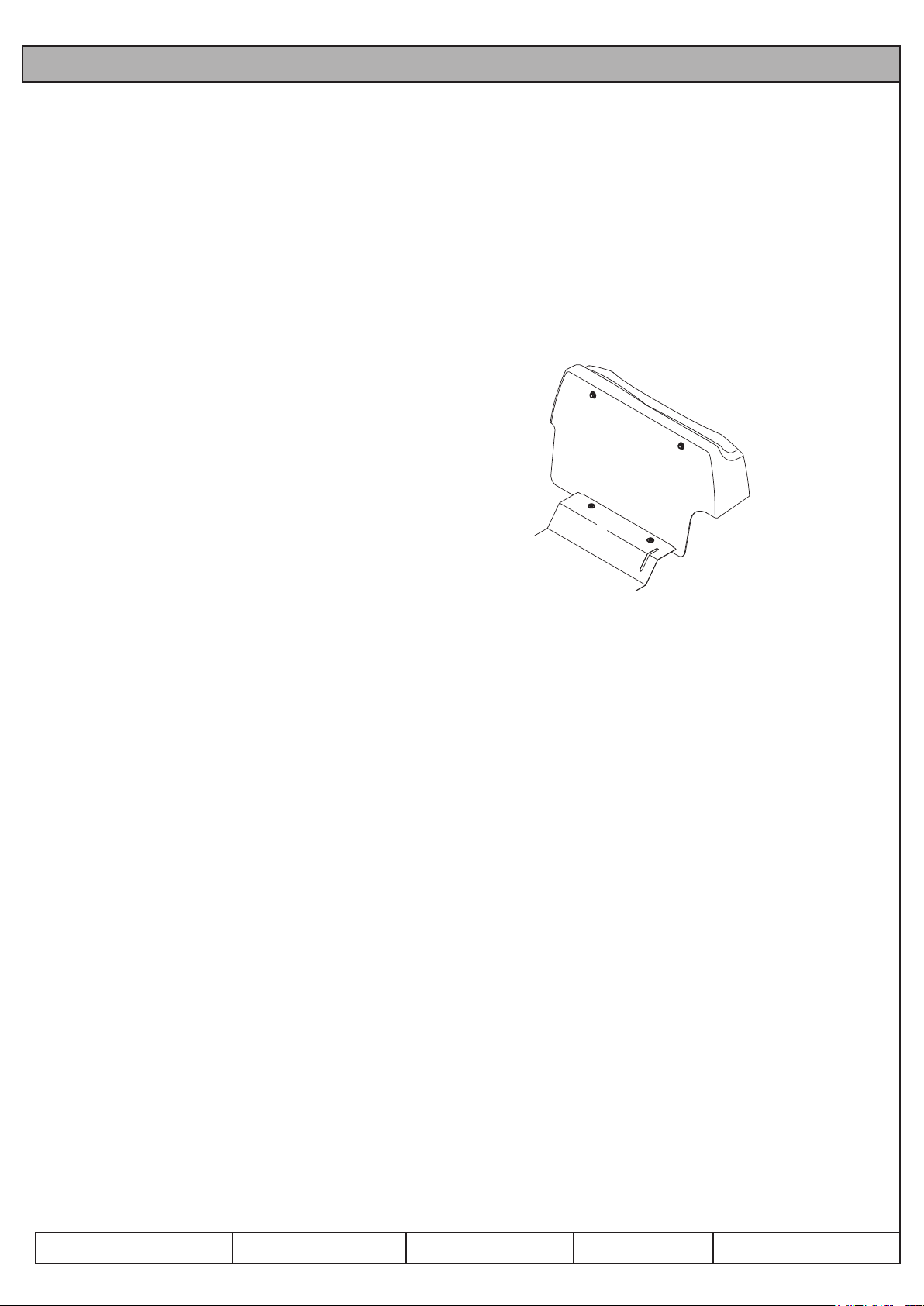
DELIVERY CHECKLIST EXPLOADED VIEW
Fig 1
Issued: 24.03.11 Approved: Mod. No. 5062856.A Sheet 5of 12 Part No. 111-5100 (A)
The LED rear indicators and rear red tail lights / stop lights attach to
the outside of the ROPS post on the left and right side and use exist-
ing bolt holes in the ROPS.
The headlights, front indicators and front white marker lights attach to
the front ROPS hoop.
The number plate with light attach to the bulkhead.
1. Open the engine cover.
2. Lift the platform.
3. Remove the bulkhead by unscrewing the 4 bolts. This is to
enable access to the main wiring loom. Refer to Fig 2.
4. Disconnect the positive cable from the battery.
5. Ensure that ROPS pivot bolts and clamp bolts are in place and
are tight.
6. Remove the ROPS pivot bolt on the left side of the mower.
7. Align the hole in the bracket (item 7) with this hole and insert the
new bolt (item 33).
8. Fit the new nut (item 26) and tighten to a torque of 15Nm.
Do not overtighten as this will make the ROPS difcult to fold.
9. Remove the ROPS pivot bolt on the right side of the mower.
10. Align the hole in the light bracket (item 6) with this hole and
insert new bolt (item 33).
11. Fit the new nut (item 26) and tighten to a torque of 15Nm.
Do not overtighten as this will make the ROPS difcult to fold.
12. NOTE: If there is already a beacon kit tted to the right side or a
waste bin kit tted to left side, it is allowable to use the same bolt
xing. It is advisable to use the new M16 nyloc nuts (item 26)
provided with this kit.
13. The light units (items 14 & 15) and the light guards (item 8) must
now be assembled onto these brackets. It is important that ALL
parts are assembled and in the correct order. The next steps refer
to the left side lights.
14. Attach the light guard (item 8) to the light bracket (item 7), on
the rear face. Attach the reector (item 10) onto the rear face
of the guard using a ZCS1F025U socket screw (item 34), plain
washer (item 28) and an M6 nyloc nut (item 25). Ensure the
reector is the correct way up. The top side is marked on the
reector. Do not overtighten at this stage until the light xing
bolts are in place.
15. Take three M5*20 setscrews (item 27) and place an M5 washer
(item 24) on each.
16. Take the red stop/tail light (item 14) and pass the screws
through the three lugs on its base.
FITTING INSTRUCTIONS
Fig 2

Issued: 24.03.11 Approved: Mod. No. 5062856.A Sheet 6of 12 Part No. 111-5100 (A)
Black
Red
Black
Red
Black
Green
Black
Green
Black
Red
Orange
Black
Red
White
Green
White
Red
Brown
Num. Plate
BLANK
BLANK
Indicator
Stop/Tail
17. Put these three screws through the three holes in the upper light
mounting position so that the red stop/tail lamp is mounted on
the rear face with the screws pointing through on the front face.
18. Place the M5 plain washer (item 24) and an M5 nyloc nut (item
23) on these three screws.
19. Repeat this procedure for the amber rear direction indicator
(without heat sink) (item 15).
20. Now tighten all xings including the centre one holding the
rear reector.
21. Feed all electrical cables down the front of the ROPS frame and
onto the electrical mount panel.
22. The cables must now be connected to the main wiring loom of
the machine and this is done with a connector lead (item 19). It
is important that the following connections are correctly made.
Refer to Fig 3.
23. Fit the 10 and 15 amp fuses as shown. Refer to Fig 4.
24. Drill a 8mm diameter hole on the centre line of the bulkhead,
15mm from the top.
25. Bolt the number plate bracket to the bulk head using items 25,
44, 45 and 46. Tighten the nut enough to allow the bolt to rotate
but not have play.
26. Replace bulk and secure with the two new number plate bolts
and two of the existing bolts.
27. Replace the bulkhead and secure with the 4 bolts. Refer to Fig 2.
28. Fit number plate bracket (item 32) with the mounting bolts for
the bulkhead.
29. Fix the number plate light (item 18) to the mounting
adjacent to the number plate (using items 11, 30 and 31).
30. Feed the cable through the 8mm hole in the bulk head. Push the
connector on the plugs. Refer to Fig 5.
31. As there isn’t a number plate light on the right side there won’t
be a connector to plug into one of the red/black connectors.
Leave this connector vacant. (Use the blanking plug to cover the
connector. Refer to Fig 3.
FITTING INSTRUCTIONS Continued
Fig 3
10A 15A 10A 10A 10A
Fig 4
Red
Black
Fig 5

Issued: 24.03.11 Approved: Mod. No. 5062856.A Sheet 7of 12 Part No. 111-5100 (A)
32. Connect the other end of the connector lead (item 19) to the main
loom connector located on the electrical mount panel.
33. Repeat this assembly procedure for the lights and connections on
the right hand side of the machine.
34. Plug the asher relay (item 13) into the vacant relay socket
located on the right side of the electrical mount panel (with the
writing in the forward position).
35. The front main lights attach to the front ROPS hoop using the
front lights mounting bracket (item 21).
36. Fix this bracket to the front ROPS hoop using two M8*25 set
screws (item 41) each side with the washer (item 38) under each
head and a washer (item 39) M8 nyloc nut (item 40) on the back.
37. Fit the lights (item 29) to the holes in the top surface of this
bracket.
38. The light units (items 16 & 17) must now be assembled onto this
bracket. The next steps refer to the left side lights.
39. Take three M5*20 setscrews (item 27) and place an M5 washer
(item 24) on each.
40. Take the front marker light (item 16) and pass the screws through
the three lugs on its base.
41. Put these screws through the three holes in the inner light
mounting position.
42. Place the M5 plain washer (item 24) and an M5 nyloc nut (item
23) on these three screws.
43. Repeat this procedure for the amber front direction indicator
(with heat sink) (item 15).
44. Connect a connector lead (item 20) to each lamp by passing the
end with just the pins, through the hole in the lamp body from
the inside so that the connector is inside the lamp.
45. Connect the connector to the lamp.
46. Now t the loose connector (item 37) to the pins on the other end
of this connector. Push the connectors into the plug as shown.
Refer to Fig 5.
FITTING INSTRUCTIONS Continued

Issued: 24.03.11 Approved: Mod. No. 5062856.A Sheet 8of 12 Part No. 111-5100 (A)
FITTING INSTRUCTIONS Continued
Limited
Lift Beacon
Hazard
Lights
Fig 7
Black
8
8
7
8
7
7
Red / White
Black
Green
Black
Blue
Front Marker
Front Indicator
Headlamp
Black 3
2
2
2
White
Green
Blue
1
6
4
8
8
8
Fig 6
47. The cables must now be connected to the main wiring loom of
the machine and this is done with a connector lead (item 42).
It is important that the following connections are correctly
carried out. Refer to Fig 6.
48. Pass the connector lead through the hole in front of the chassis
towards the cutter manifold and locate the two connectors on the
main wiring loom.
49. Plug the cables into these connectors.
50. Now the switches must be put into the control panel and
connected to the main wiring loom.
51. Remove the six screws xing the control panel to the control
pod.
52. Carefully lift off the panel ensuring that the connectors to the
existing switches are not disturbed.
53. In the rear face of the control pod, just above the key switch,
are switch blank panels beside the auto limited lift and beacon
switches. Refer to Fig 7.
54. Remove these and push the connectors and wires through the
switch hole. Connect the light and hazard switch before tting
the switch in the hole.
55. In the control panel, to the right of the horn button there is
another blanking plate. Push this out and insert the direction
indicator switch.
56. Feed the connector lead instrument panel so that the end with the
three connectors are inside the control pod.
57. Connect each connector to the correct switch using the labels as
indicators.
58. Feed the other end of this cable down the control arm and
connect to the multi pin connector on the main loom. This is
located to the right of the transmission pump.

Issued: 24.03.11 Approved: Mod. No. 5062856.A Sheet 9of 12 Part No. 111-5100 (A)
59. The final part to be fitted is the pressure switch that controls the
brake lights. This is screwed into the main transmission line.
60. Locate the three hose connections on the right side of the
transmission pump.
61. The lower front connection to the pump has a tee fitting with a
blanking cap.
62. Remove this blanking cap and screw on the pressure switch
adapter (item 12) using a ¼"dowty seal (item 36).
63. Screw the pressure switch (item 9) into this adapter.
Recommended tightening torque for these connections is 34Nm.
64. The electrical connector (item 35) must now be attached to the
cable on the main wiring loom.
65. Locate this cable (it will be coiled up and tied to the main loom
adjacent to the pressure switch). Connect wires to the plug. Refer
to Fig 8.
66. Plug the connector onto the pressure switch.
67. Cable tie all cables for the front lights, rear lights and the
pressure switch so that they are secure and to prevent them from
becoming trapped or chaffed.
68. Reconnect the battery positive cable.
69. Test the switches on the control panel to ensure that they are
handed correctly.
70. Refit the control panel ensuring that no connectors have become
detached and that no cables are nipped.
71. Lower and latch the engine cover.
72. Apply the reflectors to the engine cover. Ensure that the outside
edge of the reflector is adhered between 100-150mm from the
edge of the engine cover. Refer to Fig 9.
73. Lower and latch the operator platform.
74. Fix the serial label adjacent to the machine serial label.
FITTING INSTRUCTIONS Continued
14
23
G/Y
+BR
sig
-BU
Fig 8
Fig 9

Issued: 24.03.11 Approved: Mod. No. 5062856.A Sheet 10 of 12 Part No. 111-5100 (A)
OPERATING INSTRUCTIONS
Adjusting the headlights:
1. Loosen the nut that secures the head lights to the bracket.
2. Adjust the headlights into position by hand.
3. Tighten the nut to hold the light in the correct position.
Brake lights:
The light assembly is operated when the operator lifts their foot
off of the forward pedal or when reversing the machine.
Replace all worn or damaged parts with genuine Toro parts.
Check that all lights are working on a regular basis.
Head lights - replacing a bulb:
1. Remove the lense cover.
2. Replace the bulb.
3. Replace the lense cover.
4. Adjust lights to ensure that they comply with local road
legislation.
MAINTENANCE
SPARE PARTS
Bulb headlamp H4 Part No. 924632.

Issued: 24.03.11 Approved: Mod. No. 5062856.A Sheet 11 of 12 Part No. 111-5100 (A)
NOTES

Issued: 24.03.11 Approved: Mod. No. 5062856.A Sheet 12 of 12 Part No. 111-5100 (A)
WARRANTY
The Toro Total Coverage Guarantee
A Limited Warranty
Conditions and Products Covered
The Toro®Company and its afliate, Toro Warranty Company, pursuant
to an agreement between them, jointly warrant your Toro Commercial
product (“Product”) to be free from defects in materials or workmanship
for two years or 1500 operational hours*, whichever occurs rst. This
warranty is applicable to all products with the exception of Aerators
(refer to separate warranty statements for these products). Where a
warrantable condition exists, we will repair the Product at no cost to you
including diagnostics, labor, parts, and transportation. This warranty
begins on the date the Product is delivered to the original retail purchaser.
* Product equipped with an hour meter.
Instructions for Obtaining Warranty Service
You are responsible for notifying the Commercial Products Distributor or
Authorized Commercial Products Dealer from whom you purchased the
Product as soon as you believe a warrantable condition exists. If you need
help locating a Commercial Products Distributor or Authorized Dealer, or
if you have questions regarding your warranty rights or responsibilities,
you may contact us at:
Commercial Products Service Department
Toro Warranty Company
8111 Lyndale Avenue South
Bloomington, MN 55420-1196
E-mail: [email protected]
Owner Responsibilities
As the Product owner, you are responsible for required maintenance
and adjustments stated in your Operator’s Manual. Failure to perform
required maintenance and adjustments can be grounds for disallowing a
warranty claim.
Items and Conditions Not Covered
Not all product failures or malfunctions that occur during the warranty
period are defects in materials or workmanship. This warranty does not
cover the following:
•Product failures which result from the use of non-Toro replacement
parts, or from installation and use of add-on, or modied non-Toro
branded accessories and products. A separate warranty may be
provided by the manufacturer of these items.
•Product failures which result from failure to perform recommended
maintenance and/or adjustments. Failure to properly maintain your
Toro product per the Recommended Maintenance listed in the
Operator’s Manual can result in claims for warranty being denied.
•Product failures which result from operating the Product in an
abusive, negligent or reckless manner.
•Parts subject to consumption through use unless found to be
defective. Examples of parts which are consumed, or used up, during
normal Product operation include, but are not limited to, brakes
pads and linings, clutch linings, blades, reels, bed knives, tines,
spark plugs, castor wheels, tires, lters, belts, and certain sprayer
components such as diaphragms, nozzles, and check valves, etc.
•Failures caused by outside inuence. Items considered to be outside
inuence include, but are not limited to, weather, storage practices,
contamination, use of unapproved coolants, lubricants, additives,
fertilizers, water, or chemicals, etc.
•Normal noise, vibration, wear and tear, and deterioration.
•Normal “wear and tear” includes, but is not limited to, damage to
seats due to wear or abrasion, worn painted surfaces, scratched
decals or windows, etc.
Parts
Parts scheduled for replacement as required maintenance are warranted
for the period of time up to the scheduled replacement time for that part.
Parts replaced under this warranty are covered for the duration of the
original product warranty and become the property of Toro. Toro will
make the nal decision whether to repair any existing part or assembly or
replace it. Toro may use remanufactured parts for warranty repairs.
Note Regarding Deep Cycle Battery Warranty:
Deep cycle batteries have a specied total number of kilowatt-hours they
can deliver during their lifetime. Operating, recharging, and maintenance
techniques can extend or reduce total battery life. As the batteries in this
product are consumed, the amount of useful work between charging
intervals will slowly decrease until the battery is completely worn out.
Replacement of worn out batteries, due to normal consumption, is the
responsibility of the product owner. Battery replacement may be required
during the normal product warranty period at owner’s expense.
Maintenance is at Owner’s Expense
Engine tune-up, lubrication cleaning and polishing, replacement of
Items and Conditions Not Covered lters, coolant, and completing
Recommended Maintenance are some of the normal services Toro
products require that are at the owner’s expense.
General Conditions
Repair by an Authorized Toro Distributor or Dealer is your sole remedy
under this warranty.
Neither The Toro Company nor Toro Warranty Company is liable for
indirect, incidental or consequential damages in connection with the
use of the Toro Products covered by this warranty, including any
cost or expense of providing substitute equipment or service during
reasonable periods of malfunction or non-use pending completion
of repairs under this warranty. Except for the Emissions warranty
referenced below, if applicable, there is no other express warranty.
All implied warranties of merchantability and tness for use are limited to
the duration of this express warranty. Some states do not allow exclusions
of incidental or consequential damages, or limitations on how long an
implied warranty lasts, so the above exclusions and limitations may not
apply to you.
This warranty gives you specic legal rights, and you may also have other
rights which vary from state to state.
Countries Other than the United States or Canada
Customers should contact their Toro Distributor (Dealer) to obtain guarantee policies for your country, province, or state. If for any reason you are
dissatised with your Distributor’s service or have difculty obtaining guarantee information, contact the Toro importer. If all other remedies fail, you
may contact us at Toro Warranty Company.
374-0277 Rev A
Table of contents
Other Toro Lighting Equipment manuals


Popular Lighting Equipment manuals by other brands


ADJ
ADJ 3D VISION PLUS User instructions

HD AUDIO SYSTEM
HD AUDIO SYSTEM M-YL812 instruction manual

Larson Electronics
Larson Electronics EPLRL-50-16.4-HR-SWB quick start guide

HOMBLI
HOMBLI Smart Pathway Light manual

Milwaukee
Milwaukee HEAVY DUTY L4 NL400 user manual

Adaptive Micro Systems
Adaptive Micro Systems Beta Brite Programming manual


