Wireless Remote Controller Kit Owner’s Manual
–4–
EN
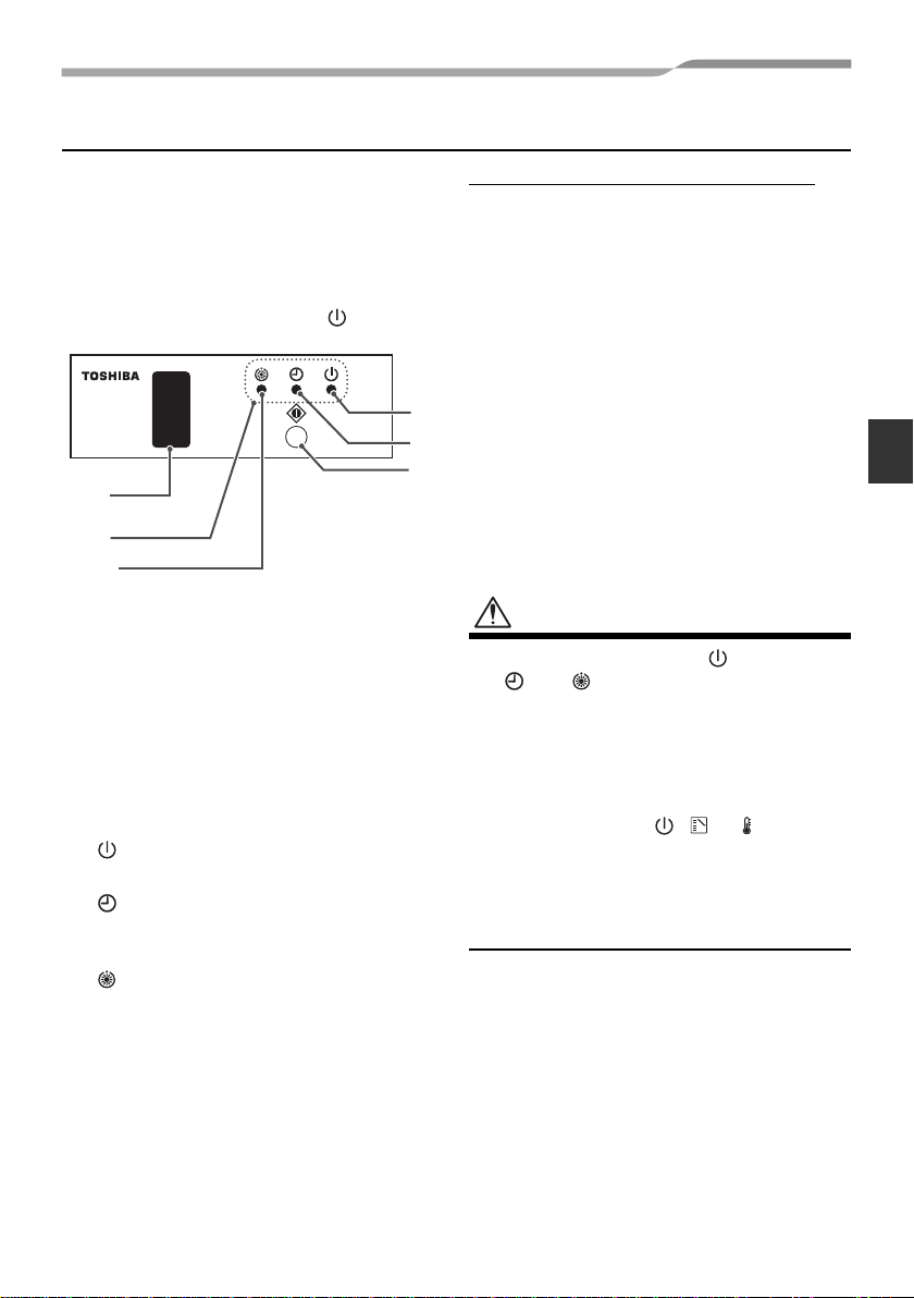
Signal Receiving Part
• Thesignalreceivingpartisattachedtothe
indoor unit.
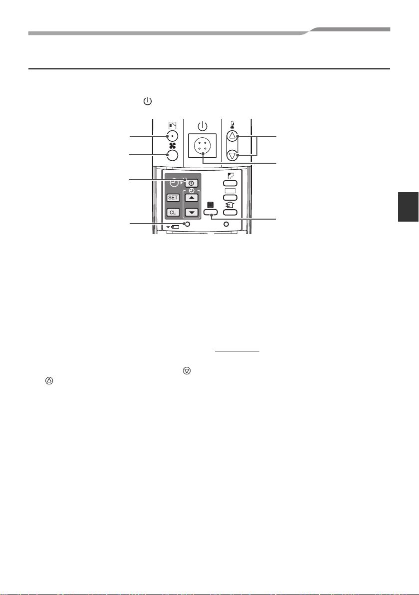
• Hereinafter, all remote controller button
names are indicated with respective
symbols displayed on the remote
controller.
Example: Start/Stop button →
1Emergency operation button
(See page 13)
2Signal receiver
Receives signals from the remote controller.
3Display lamp
Any of these lamps flashes while an error
occurs.
When an lamps flashes, see “Before Asking
for Repair Work” on page 14.
4lamp (green)
This lamp illuminates when unit is on.
5lamp (green)
This lamp illuminates while the timer is
reserved.
6lamp (orange)
• Illuminates in the heating mode at the
beginning of operation or during defrosting
or when the temperature controller is
activated.
• Flashes during an error state.
The rear of signal receiving part
The following switches are provided on the
rear of the signal receiving part. For their
settings, contact the dealer from whom you
purchased the air conditioner.
•Header/follower switch
Normally, set this switch to “HEADER” to
use the remote controller as a header.
The remote controller can be used
together with the wired remote controller
(sold separately).
•Test run switch
Donotuse this switch innormaloperation,
but use for service.
•Address switches (See page 12)
Distinguish transmit signals and receive
signals.
CAUTION
• Ifbeepisheardwiththe lightsandthe
and flashing alternately while the
heat-pump type air conditioner is used,
desired operation mode is disabled. The
same is true if the AUTO mode is
selected in a model that is not provided
with the cool/heat auto function.
• Even if you push , or when
remote controller operation is disabled
bythe centralcontrolorothermeans,“pi”
isheard5timesandthebuttonoperation
is not accepted.
2
6
3
1
4
5
4-EN
+00EH72394301.book Page 4 Monday, November 8, 2010 2:14 PM