manuals.online logo
Brands
  1. Home
  2. •
  3. Brands
  4. •
  5. Toshiba
  6. •
  7. Remote Control
  8. •
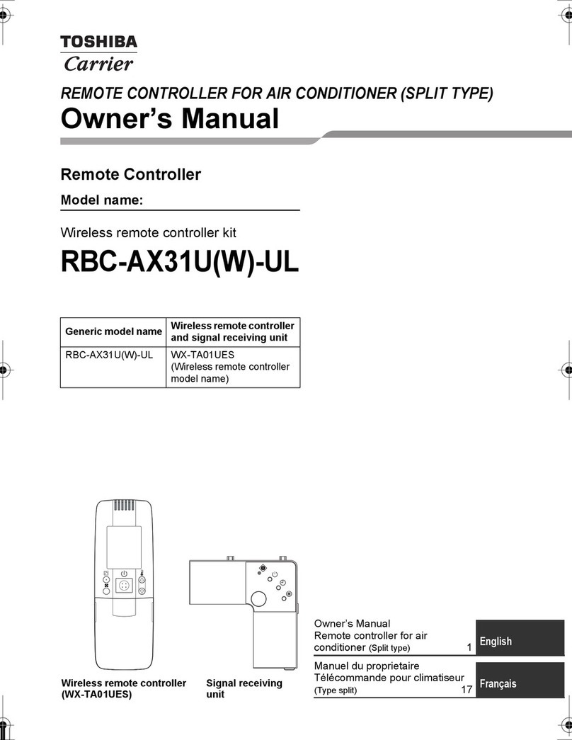
  9. Toshiba TCB-AX21E User manual

Toshiba TCB-AX21E User manual

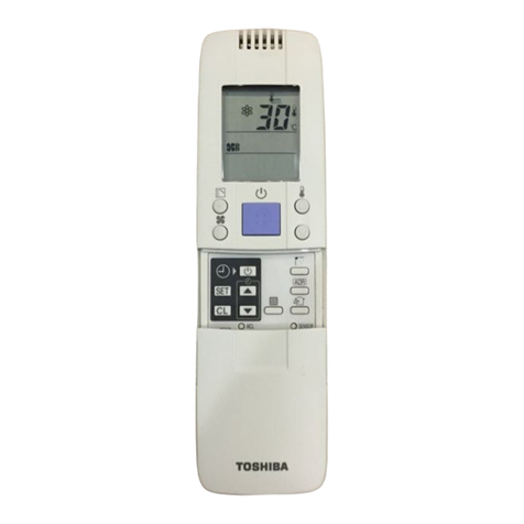
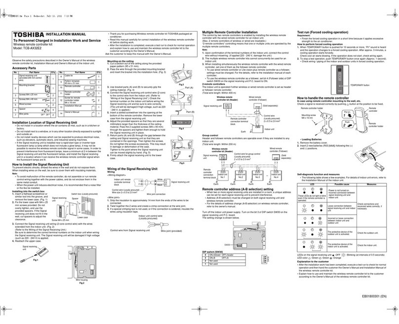
Remote ControllerWireless Kit
Kit de télécommande sans fil
Set der drahtlosen Fernbedienung
Kit per telecomando via radio
Juego de Controlador Remoto Inalámbrico
Kit do controlador remoto sem fios
Draadloze afstandsbedieningsset
Áóýñìáôï Êéô ÓõóêåõÞò Ôçëå÷åéñéóìïý
Model/Modèle/Geräte/Modello/Modelo/Modelo/Model/ÌïíôÝëï/
TCB-AX21E
INSTALLATION MANUAL
MANUEL DINSTALLATION
INSTALLATIONS-HANDBUCH
MANUALE DI INSTALLAZIONE
MANUAL DE INSTALACIÓN
MANUAL DE INSTALAÇÃO
INSTALLATIEHANDLEIDING
ÅÃ×ÅÉÑÉÄÉÏ ÅÃÊÁÔÁÓÔÁÓ Ó
Thank you very much for purchasingTOSHIBA Remote Controller for Air Conditioner.
Please read this owner's manual carefully before using your Remote Controller for Air Conditioner.
• Be sure to obtain the “Owner’s manual”and “Installation manual”from constructor (or dealer).
Request to constructor or dealer
Please clearly explain the contents of the Owner’s manual and hand over it.
Nous vous remercions pour avoir choisi une télécommande pour climatiseurTOSHIBA.
Veuillez lire attentivement ce Manuel du propriétaire avant d’utiliser votre télécommande pour climatiseur.
• Assurez-vous que le constructeur (ou le revendeur) vous remette le“Manuel du propriétaire” et le“Manuel
d’installation”.
Demande au constructeur ou au revendeur
Veuillez expliquer clairement le contenu du Manuel du propriétaire et le remettre au client.
Wir danken Ihnen, dass Sie sich für eineTOSHIBA Fernbedienung für Klimageräte entschieden haben.
Bitte lesen Sie diese Bedienungsanleitung sorgfältig, ehe Sie Ihre Fernbedienung für Klimageräte benutzen.
• Lassen Sie sich die “Bedienungsanleitung” und das “Installations-Handbuch”unbedingt vom Installateur oder vom
Lieferanten aushändigen.
Eine Bitte an den Installateur oder Lieferanten:
Bitte erklären Sie dem Käufer den Inhalt der Bedienungsanleitung und händigen sie ihm aus.
Grazie di aver acquistato un telecomandoTOSHIBA per condizionatore d'aria.
Prima di usare il telecomando per condizionatore d'aria, leggere con attenzione questo manuale del proprietario.
• Si raccomanda di tenere a portata di mano il "Manuale del proprietario" e il "Manuale di installazione" ricevuti dal
produttore (o dal rivenditore).
Richiesta al produttore o al rivenditore
Spiegare chiaramente il contenuto del Manuale del proprietario e consegnarne una copia all'utente.
Muchas gracias por haber adquirido el control remotoTOSHIBA para su aparato de aire acondicionado.
Lea atentamente este manual del propietario antes de utilizar el control remoto para el aparato de aire acondicionado.
• Asegúrese de que el fabricante (o distribuidor) le proporcione el“Manual del propietario” y el “Manual de
instalación”.
Solicitud al fabricante o distribuidor
Explique con claridad el contenido del Manual del propietario y entréguelo al cliente.
Hartelijk dank voor uw keuze voor een afstandsbediening bij uw airconditioner vanTOSHIBA.
Lees deze gebruiksaanwijzing zorgvuldig door voordat u de afstandsbediening gaat gebruiken.
• Zorg ervoor dat u zowel de‘gebruiksaanwijzing’als de‘installatiehandleiding’van de installateur (of leverancier)
krijgt.
Verzoek aan de installateur of de leverancier
Leg de inhoud van de gebruiksaanwijzing duidelijk uit en overhandig de gebruiksaanwijzing nadien aan de klant.
Agradecemos o facto de ter adquirido o Controlador Remoto para Ar Condicionado da TOSHIBA.
Lei atentamente o presente Manual do Utilizador antes de utilizar o Controlador Remoto para Ar Condicionado.
• Peça o “Manual do Utilizador”e o“Manual de Instalação”ao fabricante (ou concessionário).
Peça ao fabricante ou representante
Explique claramente o conteúdo do Manual do Utilizador e proceda à sua entrega.
Óáò åõ÷áñéóôïýìå ðïëý ðïõ ðñïôéìÞóáôå ôçí TOSHIBA ãéá ôç ÓõóêåõÞ Ôçëå÷åéñéóìïý ãéá Êëéìáôéóôéêü
Ðáñáêáëïýìå äéáâÜóôå ðñïóåêôéêÜ ôéò ïäçãßåò ÷ñÞóçò ðñéí áðü ôç ÷ñÞóç ôçò ÓõóêåõÞò Ôçëå÷åéñéóìïý ãéá
Êëéìáôéóôéêü

Öñïíôßóôå íá ðñïìçèåõôåßôå ôï Åã÷åéñßäéï ×ñÞóôç êáé ôï Åã÷åéñßäéï ÅãêáôÜóôáóçò áðü ôïí êáôáóêåõáóôÞ (Þ ôïí ðùëçôÞ)
ÐáñÜêëçóç ãéá ôïí êáôáóêåõáóôÞ Þ ôïí ðùëçôÞ
Ðáñáêáëþ åîçãÞóôå ìå óáöÞíåéá ôá ðåñéå÷üìåíá ôùí Ïäçãéþí ×ñÞóçò êáé ðáñáäþóôå ôï
ENGLISHFRANCAISDEUTSCHITALIANOESPANOLPORTUGUESNEDERLANDSΕΛΛΗΝΙΚΑ
中文
CONTENTS
Accessory parts ................................................................................1
Switch location of receiver unit .........................................................2
Installation location of receiver unit ...................................................2
How to install the receiver unit ..........................................................3
How to perform cabling of sensor units .............................................6
Requirement .....................................................................................7
How to set the room temperature sensor ..........................................8
How to set the address switch ..........................................................8
Slide switch ...................................................................................... 9
Self-diagnosis table and measures .................................................. 9
Cautions for installation of the remote controller ............................ 10
Explanation to customers ............................................................... 10
How to handle the remote controller .............................................. 10
Test run .......................................................................................... 11
SOMMAIRE
Pièces accessoires .........................................................................12
Emplacement des commutateurs de l’unité réceptrice ...................13
Emplacement d’installation de l’unité réceptrice .............................13
Installation de l’unité réceptrice .......................................................14
Mode de raccordement des détecteurs ..........................................17
Conditions requises ........................................................................18
Mode de réglage du détecteur de température ambiante ...............19
Mode de réglage du commutateur d’adresse .................................19
Curseur ........................................................................................... 20
Tableau d’autodiagnostic et mesures ............................................. 20
Précautions concernant l’installation de la télécommande ............. 21
Explication destinée aux clients ..................................................... 21
Mode de manipulation de la télécommande ................................... 21
Essai de fonctionnement ................................................................ 22
INHALT
Zubehörteile ....................................................................................23
Anordnung der Schalter an der Empfängereinheit ..........................24
Installationsort der Empfängereinheit .............................................24
Installieren der Empfängereinheit ...................................................25
Verkabelung des Sensors ...............................................................28
Voraussetzungen ............................................................................29
Auswahl des Raumtemperaturfühlers .............................................30
Einrichten der verschiedenen Adressen .........................................30
Schiebeschalter .............................................................................. 31
Selbstdiagnose und Maßnahmen ................................................... 31
Vorsichtsmaßnahmen bei der Installation der Fernbedienung .......32
Erklärung für den Kunden .............................................................. 32
Handhabung der Fernbedienung ................................................... 32
Testlauf ........................................................................................... 33
INDICE
Accessori ........................................................................................34
Ubicazione dell’interruttore dell’unità ricevente ...............................35
Ubicazione per l’installazione dell’unità ricevente ...........................35
Come installare l’unità ricevente .....................................................36
Come eseguire il cablaggio delle unità sensore .............................39
Requisiti ..........................................................................................40
Come impostare il sensore della temperatura del locale ................41
Come impostare i diversi indirizzi ...................................................41
Come impostare il sensore della temperatura del locale ............... 41
Interruttore a scorrimento ............................................................... 42
Tabella e misurazioni di autodiagnosi ............................................ 42
Precauzioni per l’installazione del telecomando ............................. 43
Spiegazioni ai clienti ....................................................................... 43
Come installare il telecomando ...................................................... 43
Funzionamento di prova ................................................................. 44
CONTENIDO
Partes accesorias ...........................................................................45
Ubicación del interruptor de la unidad receptora ............................46
Lugar de instalación de la unidad receptora ...................................46
Cómo instalar la unidad receptora ..................................................47
Cómo preparar el cableado de las unidades sensoras ...................50
Requisitos .......................................................................................51
Cómo configurar el sensor de temperatura ambiente .....................52
Cómo configurar el interruptor de dirección ....................................52
Conmutador deslizante .................................................................. 53
Tabla y medidas de diagnóstico automático .................................. 53
Precauciones para la instalación del control remoto ...................... 54
Explicación a los clientes ............................................................... 54
Cómo utilizar el control remoto ....................................................... 54
Prueba de funcionamiento ............................................................. 55
ÍNDICE
Acessórios ......................................................................................56
Localização do interruptor da unidade de recepção .......................57
Local de instalação da unidade de recepção ..................................57
Como instalar a unidade de recepção ............................................58
Como instalar os cabos das unidades sensoras ............................61
Requisito .........................................................................................62
Como configurar o sensor de temperatura do compartimento .......63
Como configurar o interruptor de endereços ..................................63
Interruptor de correr ....................................................................... 64
Quadro e medidas de autodiagnóstico ........................................... 64
Cuidados a ter na instalação do controlador remoto ...................... 65
Explicação aos clientes .................................................................. 65
Como utilizar o controlador remoto ................................................ 65
Ensaio de funcionamento ............................................................... 66
INHOUD
Toebehoren .....................................................................................67
Schakelaars op het ontvangtoestel .................................................68
Installatieplaats van het ontvangtoestel ..........................................68
Installeren van het ontvangtoestel ..................................................69
Zo sluit u de bekabeling van de sensorunits aan ............................72
Voorwaarde .....................................................................................73
Zo stelt u de ruimtetemperatuursensor in .......................................74
Zo stelt u de adresschakelaar in .....................................................74
Verschuif de schakelaar ................................................................. 75
Zelfdiagnosetabel en maatregelen ................................................. 75
Let op de volgende punten bij de installatie van de
afstandsbediening .......................................................................... 76
Uitleg voor de klant ......................................................................... 76
Over de afstandsbediening ............................................................ 76
Werkingstest ................................................................................... 77
ΠΕΡΙΕΧΟΜΕΝΑ
Παρελκενα ανταλλακτικά ...................................................................78
Θέση διακπτη της µονάδας λήψης ......................................................79
Θέση εγκατάστασης της ονάδας λήψης .............................................79
Πώς να εγκαταστήσετε τη ονάδα λήψης ............................................80
Πώς να πραγµατοποιήσετε την καλωδίωση των µονάδων
αισθητήρα .................................................................................................83
Προϋπθεση .............................................................................................84
Πώς να ρυθµίσετε τον αισθητήρα της θερµοκρασίας δωµατίου .......85
Πώς να ρυθµίσετε τον διακπτη διευθύνσεων ................................... 85
Συρµενος διακπτης ............................................................................ 86
Πίνακας αυτο-διάγνωσης και µέτρων ................................................... 86
Προφυλάξεις για την εγκατάσταση της συσκευής τηλεχειρισµού ... 87
Επεξήγηση στους πελάτες .................................................................... 87
Πώς να χειρίζεστε τη συσκευή τηλεχειρισµού .................................... 87
∆οκιµή Λειτουργίας ................................................................................ 88
目录
附件 .................................................................................................89
接收装置的开关位置 ........................................................................90
接收装置的安装 ...............................................................................90
如何安装接收装置 ...........................................................................91
附怎样进行传感器装置的布线件 ......................................................94
要求 .................................................................................................95
怎样设置室温传感器 ........................................................................96
怎样设置地址开关 ........................................................................... 96
滑动开关 ......................................................................................... 97
自我诊断表和对策 ........................................................................... 97
安装遥控器时的注意 ....................................................................... 98
对用户的说明 .................................................................................. 98
怎样使用遥控器 .............................................................................. 98
试运转 ............................................................................................. 99
EN-BookTOC.fm Page 1 Monday, June 14, 2004 8:53 PM
1
CONTENTS
Accessory parts
No. Parts Quantity
1
Separate receiver unit
(provided 200mm power cable) 1
2
Plate mounting
1
3Screws M4 x 25 2
4Screws M4 x 40 2
5Wood screws 2
6Spacer 4
7Wire joints 2
8Clamp 1
9Pattern template
95 x 51 1
EN-Book.book Page 1 Monday, June 14, 2004 8:14 PM
2
ENGLISH
• Do not install in a location where the air contains oil mist, such as in a kitchen or factory.
• Do not install next to a window, or in any other location directly exposed to sunlight and outside air.
• Do not install nearby devices which can be expected to produce electrical noise, such as elevators,
automatic doors, and industrial sewing machines.
• If the receiver unit is installed near a rapid-start type or inverter-type fluorescent lamp (a lamp which
does not include a glow lamp), it may not be possible to receive the wireless remote controller signal
in some cases. In order to prevent interference from fluorescent lamps, leave a minimum of 2 meters
between the receiver unit and the fluorescent lamps, and install the receiver unit in a location where it
can receive the wireless remote controller signal when the fluorescent lamps are lit.
Switch location of receiver unit
Installation location of receiver unit
Address selector switch
This switch is used to address
one of a maximum of six air con-
ditioners that can be controlled by
the remote controller.
All /NORMAL selector switch
Set this switch to the “NORMAL” position for the normal operation of the air conditioner. When this
switch is set to the “ALL ” position, the indoor unit of the air conditioner is turned off.
RCU:SUB/RCU:MAIN selector switch
Set this switch to the “RCU:MAIN” position for normal operation. Refer to page 7 for setting to the
“RCU:SUB” position.
PCB CHK switch
This switch is not used and should be set in the position shown in the figure.
TEST RUN switch
This switch is used for test running.
EN-Book.book Page 2 Monday, June 14, 2004 8:14 PM
3
NOTES :
• To avoid malfunction of the remote controller, do not assemble or run remote control wiring together
with the power cables, and do not enclose them in the same metal conduit.
• When the power unit induces electrical noise, it is recommended that a noise filter or the like be
installed.
How to install the receiver unit
For flush mounting into a wall, install the separate receiver unit in a metal switch box (field
supply) that has been recessed into the wall in advance.
1. Insert a flathead screwdriver or similar tool
into the notch, and remove the face plate.
2. Fix the receiver unit with 2 M4 screws pro-
vided. Do not overly tighten, and use the pro-
vided spacers. If the receiver unit does not fit
in the wall, cut spacers to adjust the clear-
ance.
3. Connect the receiver unit wiring (2-core cable)
with the cables extended from the indoor unit.
(Refer to the section on receiver unit wiring.)
Be sure to determine the correct terminal
numbers on the indoor unit when wiring the
receiver unit. The remote controller will be
damaged if high voltage (such as 200 VAC) is
applied.
4. Reinstall the face plate.
13
2
46
5
Spacer
M4 x 25
(2)
Receiver unit
Remove Face plate
Spacer
EN-Book.book Page 3 Monday, June 14, 2004 8:14 PM
4
When using exposed mounting for the receiver unit, install onto a wall where the receiver unit
can be attached.
1. Insert a flathead screwdriver or similar tool
into the groove on the bottom of the receiver
unit. Pry open with the screwdriver and
remove the lower case. (Fig. A).
Fig.A
2. In order to later pass the receiver wiring out
through the upper case (thin part at the top
center), use nippers or a similar tool to cut a
notch in the same size as the remote control-
ler cord (optional). (Fig. B)
Fig.B
3. Disconnect the wires that were connected to
the connector at the time of shipment.
4. Fasten the remote controller cord (optional) at
the position shown in Fig. C, using the pro-
vided clamper. Then connect the cord to the
receiver connector.
Fig.C
5. Shape the remote controller cord as shown in
Fig. C so that it fits at the top inside the
receiver unit, above the PCB. Then attach the
lower case. At this time, bend the head of the
clamp so that it faces sideways.
6. Remove the nameplate and use 2 wood
screws to attach the receiver unit.
7. Use the provided cord clips to fasten the
remote controller cord to the wall.
8. Reattach the nameplate.
Face plate
Notch where remote control-
ler cord passes through top
case
Clamp
Connector Remote controller
cord (optional)
2–3mm
13
2
46
5
Clamp
Remote controller cord
(optional)
Wood
screws (2)
Receiver unit
EN-Book.book Page 4 Monday, June 14, 2004 8:14 PM
5
If the separate receiver unit is installed on the ceiling, use the provided ceiling mounting
bracket for installation.
1. Insert a screwdriver or similar tool into the notch
at the bottom to remove the receiver nameplate.
2. Cut a section out of the ceiling along the provided
paper pattern (95 x 51 mm).
3. Pass the wire through the provided mounting
bracket and insert the bracket into the installation
hole. (Fig. D)
Fig.D
4. Use bracket parts (A) and (B) to securely grip the
ceiling material. (Fig. E)
Fig.E
5. Connect the receiver wire (2-core) to the wire
from the indoor unit. (Refer to “Wiring the
Receiver Unit.”) Check the terminal number on
the indoor unit before wiring the receiver unit and
be sure not to wire incorrectly. (The unit will be
damaged if high voltage, such as 200 VAC, is
applied.)
6. Adjust the provided spacers so that they are sev-
eral millimeters larger than the thickness of the
ceiling material. Pass the 2 supplied screws (M4 x
40) through the spacers and tighten them enough
to hold the receiver unit in place.
7. Return parts (A) and (B) through the gap between
the ceiling and receiver unit so that they are con-
tained in the openings. Then tighten the screws.
Do not tighten the screws excessively. This may
result in damage or deformation of the case.
Tighten to the point where the receiver unit can
be moved slightly by hand. (Fig. F)
Fig.F
8. Reattach the nameplate.
Part (A)
Part (B)
EN-Book.book Page 5 Monday, June 14, 2004 8:14 PM
6
• Provided wire joint (WHT 2)
How to perform cabling of sensor units
Flush Mounting
• Connection diagram
1. Strip the insulation to approximately 14 mm
from the ends of the wires to be connected.
2. Twist together the 2 wires and create a crimp
connection at the wire joint.
3. If a special crimping tool is not used, or if the
connection is soldered, insulate the wires
using insulation tape.
Exposed Mounting
• Connection diagram
Indoor unit remote
controller terminal
board
Separate receiver
unit
Power wire from
receiver unit
Connector
Wire of
receiver unit
(field supply)
Wire of receiver unit
(field supply)
Power wire from
receiver unit Wire joint CE-1
(provided)
Separate receiver
unit
Indoor unit remote
controller terminal
board
Remote controller cord (optional)
EN-Book.book Page 6 Monday, June 14, 2004 8:14 PM
7
The control by two remote controllers is enabled by installing the wireless remote controller with the
wired remote controller for an indoor unit.
(Max. 2 remote controllers of wireless or wired are insatiable.)
“2-remote controllers” controlling means that one or multiple units are operated by the multiple remote
controllers.
NOTES :
1. Upon confirmation of the terminal numbers of the indoor unit, connect the remote controller cables
without miscabling. (If applied AC 220–240 Volt, damage the unit.)
2. The multiple wireless remote controller kits cannot concurrently be used for an indoor unit.
3. When installing simultaneously the wireless remote controller with the wired remote controller, set
one of them as the sub remote controller.
• When setting the wired remote controller as the sub, exchange the address connector at the rear
of P.C. board of wired remote controller from master to sub remote controller.
• When setting the wireless remote controller as the sub, turn the switch of wireless remote control-
ler receiver unit from RCU: MAIN to RCU:SUB.
To operate an indoor unit by 2 remote controllers
To operate a group control of multiple indoor units by 2 remote controllers
Requirement
The indoor unit is operated if either wireless or wired remote controller is set as master or sub remote
controller.
(Total cable length: Within 400m)
Master and Sub remote controllers are operable even if they are installed to any indoor unit.
(Total cable length: Within 200m)
Wireless remote controller kit
(Master) Wired remote controller
(Sub)
Sensor unit (Sold separately) (Sold separately)
Indoor unit
Te r min al b lock fo r
remote controller cable
Earth
Remote controller cable
(Procured locally)
(0.5 to 2mm2)
(Sold separately)
Wireless remote controller kit
(Master)
Wired remote controller
(Sub)
(Sold separately)
Earth Earth Earth Earth
Terminal block for
remote controller
cable
Sensor unit
Remote controller inter-unit cable for group
control (Procured locally)
(0.5 to 2mm²)
Indoor unit
No.1 Indoor unit
No.2 Indoor unit
No.3 Indoor unit
No.N
EN-Book.book Page 7 Monday, June 14, 2004 8:14 PM
8
• The room temperature sensors are equipped in the indoor unit and the wireless remote controller.
One of two sensors works.
• The room temperature sensor is set to the indoor unit side at the shipment from the factory.
To select the sensor in the remote controller, push the SENSOR button (Right figure) inside of the
remote controller cover and check “Main sensor” disappears from LCD.
• When the multiple sensors are installed in the same room, an address can be set to prevent cross
communication.
• When replacing the battery and pushing SET button, the address of the remote controller becomes
[ALL] and the sensor is enabled to receive signal regardless of setting of address switch of the opera-
tion section.
• For selecting of the remote controller address, refer to Owner’s Manual.
• Change the address of the sensor by removing screws of P.C. board cover of the sensor unit. After
then, fix the cover with screws using a clamp.
How to set the room temperature sensor
NOTE :
If the room temperature data from the remote controller is not
transmitted to the unit for 10 minutes or more, the sensor at
indoor unit side is automatically selected even if the sensor at the
remote controller side is selected.
Fix the remote controller toward the unit as possible.
How to set the address switch
Display of
remote
controller
address
Address Address Address
• • • • •
Address
Address switch
position of
sensor
Address
switch of
sensor unit
can be set any
position.
• • • • •
Sensor
button
EN-Book.book Page 8 Monday, June 14, 2004 8:14 PM
9
• Check the slide switch in the battery box of the remote controller is set to [S] / [A] at shipment from the
factory.
Lamp indication of sensor
: Goes off
: Flash
(0.5-sec. interval)
Slide switch
Select of operation mode follow as below table.
Digital Inverter
(RAV) Super Modular Multi
(Heat pump type) Super Modular Multi
(Cooling only type)
Slide
switch
position
Select of flap indication set to S.
Self-diagnosis table and measures
Lamp indication Cause Measures
Power supply is not turned on.
Miscabling between sensor unit and indoor
unit
Check cable
connection and correct
it.
No indication even if the
remote controller is operated.
Defective connection between sensor unit
and indoor unit
Miscabling or defective connection
between indoor and outdoor units
Protective device of outdoor unit works. Check outdoor unit.
Flashes alternatively
Protective device of indoor unit works. Check indoor unit.
Flashes alternatively
SKN AHC
A H C A H C A H C
SKN
EN-Book.book Page 9 Monday, June 14, 2004 8:14 PM
10
• To operate the remote controller by fixing it to the wall, etc. with a remote controller holder, turn on the
fluorescent lamp, operate the remote controller at the position to be fixed, check the air conditioner
normally operates, and then mount it.
• When the room temperature is sensed by the remote controller, mount the remote controller paying
attention to the following items.
• Place not exposed directly to cold or hot wind.
• Place not exposed directly to the sunlight.
• Other places where the remote controller is not influenced.
• Hand over the “Owner’s Manual” and “Installation Manuals” to the customer after installation works.
• Explain usage and maintenance of the remote controller according to “Owner’s Manual”.
.
Cautions for installation of the remote controller
Explanation to customers
How to handle the remote controller
In case using remote controller mounting to
the wall, etc.
Check a signal is received correctly by pushing
button at the position to be fixed.
Replacement of battery
1. Holding the both ends of the cover and
remove it by sliding downward.
2. Correctly insert 2 AAA alkali batteries match-
ing + and - polarities with indications.
3. Push SET button with something tipped and
attach the cover.
Mounting screw
Truss tapping 4 x 16 Put on.
Push.
• To take off remote controller,
pull it toward you.
Cover RESET button
EN-Book.book Page 10 Monday, June 14, 2004 8:14 PM
11
Before test run
• Before turning on the power supply, carry out the following procedure.
1) Using 500V-megger, check 1MΩor more exists between the terminal block 1 to 3 and the earth. If
1MΩor less is detected, do not run the unit. Do not apply to the remote controller circuit.
2) Check the valve of the outdoor unit being opened fully.
• To protect the compressor at activation time, leave power-ON for 12 hours or more be for operating.
How to conduct a test run
CAUTION:
Do not set the switch to the “TEST RUN” position other than for test running.
The air conditioner may be damaged if this switch is set to the “TEST RUN” position for normal operation.
(The receiver unit automatically turns off the air conditioner 60 minutes after the switch has been set to
the “TEST RUN” position to prevent continuous test running.)
Test run
1. Remove the face plate from the receiver unit.
Set the “TEST RUN” switch to the “TEST
RUN” position.
2. Press the button on the wireless remote
controller to start the operation of the air con-
ditioner.
The , , and lamps each light under test
running.
The temperature cannot be set by the wire-
less remote controller with the “TEST RUN”
switch is set to the “TEST RUN” position.
3. Operate the air conditioner in the “heating”,
“cooling”, or “fan only” mode during test run-
ning.
The outdoor unit will not operate for approxi-
mately 3 minutes after the air conditioner has
been turned on or off.
EN-Book.book Page 11 Monday, June 14, 2004 8:14 PM
85464359606000

Other manuals for TCB-AX21E

1

Other Toshiba Remote Control manuals

Toshiba RBC-ASC11E User manual

Toshiba

Toshiba RBC-ASC11E User manual

Toshiba RB-RXS33-E User manual

Toshiba

Toshiba RB-RXS33-E User manual

Toshiba RBC-AX32UW-UL User manual

Toshiba

Toshiba RBC-AX32UW-UL User manual

Toshiba RBC-AX23UWW-E User manual

Toshiba

Toshiba RBC-AX23UWW-E User manual

Toshiba RBC-AMTU31-E User manual

Toshiba

Toshiba RBC-AMTU31-E User manual

Toshiba RBC-AX22CE2 User manual

Toshiba

Toshiba RBC-AX22CE2 User manual

Toshiba TCB-SC642TLE2 User manual

Toshiba

Toshiba TCB-SC642TLE2 User manual

Toshiba RBC-AMT31-E User manual

Toshiba

Toshiba RBC-AMT31-E User manual

Toshiba Carrier RBC-AX22CUL User manual

Toshiba

Toshiba Carrier RBC-AX22CUL User manual

Toshiba RBP-RC001-E Operating instructions

Toshiba

Toshiba RBP-RC001-E Operating instructions

Toshiba Carrier TCB-AX21UL User manual

Toshiba

Toshiba Carrier TCB-AX21UL User manual

Toshiba 2358 9721 User manual

Toshiba

Toshiba 2358 9721 User manual

Toshiba RBC-AX33UYP-E User manual

Toshiba

Toshiba RBC-AX33UYP-E User manual

Toshiba Regza 32WLT68 User manual

Toshiba

Toshiba Regza 32WLT68 User manual

Toshiba RBC-AMS54E User manual

Toshiba

Toshiba RBC-AMS54E User manual

Toshiba RBC-AX31U(W)-UL User manual

Toshiba

Toshiba RBC-AX31U(W)-UL User manual

Toshiba RBC-AS21E User manual

Toshiba

Toshiba RBC-AS21E User manual

Toshiba Carrier RBC-AMS41UL User manual

Toshiba

Toshiba Carrier RBC-AMS41UL User manual

Toshiba RB-RWS20-E User manual

Toshiba

Toshiba RB-RWS20-E User manual

Toshiba RBC-AS21E User manual

Toshiba

Toshiba RBC-AS21E User manual

Toshiba 15V300PG User manual

Toshiba

Toshiba 15V300PG User manual

Toshiba RBC-AS41E User manual

Toshiba

Toshiba RBC-AS41E User manual

Toshiba Carrier RBC-AX22CUL User manual

Toshiba

Toshiba Carrier RBC-AX22CUL User manual

Toshiba RBC-AS21UL User manual

Toshiba

Toshiba RBC-AS21UL User manual

Popular Remote Control manuals by other brands

Vetus RCM2 Operation manual and installation instructions

Vetus

Vetus RCM2 Operation manual and installation instructions

Sony RM-PP401 Operating Instructions  (primary... operating instructions

Sony

Sony RM-PP401 Operating Instructions (primary... operating instructions

KDS Models KDS-7XII instruction manual

KDS Models

KDS Models KDS-7XII instruction manual

JJC TM Series instruction manual

JJC

JJC TM Series instruction manual

FUTABA FP-G134 instruction manual

FUTABA

FUTABA FP-G134 instruction manual

Kludi 76790 operating instructions

Kludi

Kludi 76790 operating instructions

Panasonic AWCB400N - REMOTE OPERATION PANEL operating instructions

Panasonic

Panasonic AWCB400N - REMOTE OPERATION PANEL operating instructions

Sena RC4 Operation

Sena

Sena RC4 Operation

fakro ZWP10 user manual

fakro

fakro ZWP10 user manual

LG MR20PJTR User information

LG

LG MR20PJTR User information

SkyLink EM-101 manual

SkyLink

SkyLink EM-101 manual

SWL remote control for ICOM operating manual

SWL

SWL remote control for ICOM operating manual

Kenwood KRK-10 Installation

Kenwood

Kenwood KRK-10 Installation

RCA RCRPS04GR Guía de inicio Rápido

RCA

RCA RCRPS04GR Guía de inicio Rápido

Louvolite 1CH operating instructions

Louvolite

Louvolite 1CH operating instructions

Ltech F1 manual

Ltech

Ltech F1 manual

URC MX-890 instructions

URC

URC MX-890 instructions

Fujitsu Airstage UTY-DCGYZ1 operating manual

Fujitsu

Fujitsu Airstage UTY-DCGYZ1 operating manual

manuals.online logo
manuals.online logoBrands
  • About & Mission
  • Contact us
  • Privacy Policy
  • Terms and Conditions

Copyright 2025 Manuals.Online. All Rights Reserved.