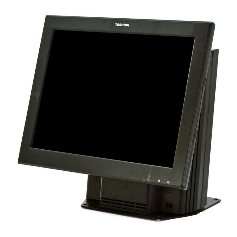
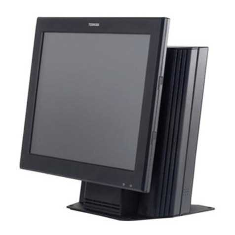
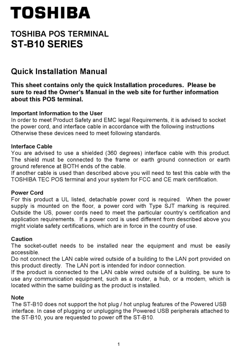
Toshiba ST-B10 SERIES User manual

PRINTED IN JAPAN
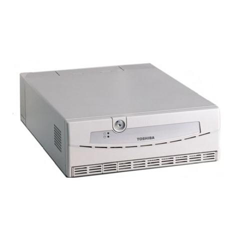
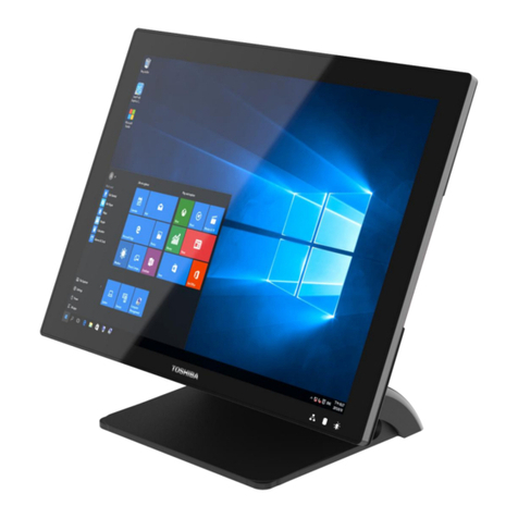
TOSHIBA POS Terminal
ST-B10 SERIES
Document No. EO18-12017
Original Mar., 2010
(Revised )
Maintenance Manual

WARNING!
Follow all manual instructions. Failure to do so could create safety hazards such as fire or
electrocution.
NOTES: 1. Manual instructions must be followed when installing option kits or adding cables to
avoid system failures and to insure proper performance and operation.
2. Failure to follow manual instructions or any unauthorized modification, substitution
or change to this product will void the limited product warranty.

EO18-12017
TABLE OF CONTENTS
Page
1. UNPACKING .............................................................................................................. 1- 1
1.1 Procedure .......................................................................................................................................1- 1
1.2 Checks ............................................................................................................................................1- 2
1.3 Tapes ..............................................................................................................................................1- 2
1.4 Notes for Installation .......................................................................................................................1- 2
2. INSTALLATION PROCEDURE FOR OPTIONAL EQUIPMENT................................ 2- 1
2.1 Removing/Attaching the Top Cover................................................................................................2- 2
2.2 Installing the Hard Disk Drive (HDD) ..............................................................................................2- 4
3. MAIN UNIT REPLACEMENT ..................................................................................... 3- 1
3.1 Replacing the Main Board .............................................................................................................. 3- 1
3.2 Replacing the LVDS Display Card..................................................................................................3- 4
3.3 Replacing the PS Unit..................................................................................................................... 3- 8
3.4 Replacing the Fan Motor ...............................................................................................................3-11
3.5 Replacing the Panel Card..............................................................................................................3-15
4. BIOS SETUP .............................................................................................................. 4- 1
4.1 General ...........................................................................................................................................4- 1
4.2 Basic Operation and Keys Used.....................................................................................................4- 1
4.3 BIOS Setup Screen Configuration and Default Setting .................................................................. 4- 6
4.4 Notes and Restrictions...................................................................................................................4-28
Appendix-1 BIOS Error Message List.....................................................................................................4-31
5. DIAGNOSTIC TEST OPERATION ............................................................................. 5- 1
5.1 Outline.............................................................................................................................................5- 1
5.2 Serviceman Diagnostic Test Program Setup Procedure................................................................ 5- 2
5.3 ST-B10 Diagnostic Menu................................................................................................................5- 5
5.4 Serviceman Diagnostic Test Program ............................................................................................5- 6
6. PERIODIC MAINTENANCE ....................................................................................... 6- 1
6.1 Procedure of Periodic Maintenance ............................................................................................... 6- 1
7. TROUBLESHOOTING................................................................................................ 7- 1
EO18-12017
CAUTION!
1. This manual may not be copied in whole or in part without prior written permission of TOSHIBA
TEC.
2. The contents of this manual may be changed without notification.
3. Please refer to your local Authorised Service representative with regard to any queries you
may have in this manual.
Copyright © 2010
by TOSHIBA TEC CORPORATION
A
ll Rights Reserved
570 Ohito, Izunokuni-shi, Shizuoka-ken, JAPAN
NOTE: Pictures in this manual show that body colour may differ from that of the original.
8. APPENDIX.................................................................................................................. 8- 1
8.1 Serial Interface COM1 to COM6.....................................................................................................8- 1
8.2 VGA Connector...............................................................................................................................8- 2
8.3 DRW1 (Cash Drawer 24V Type) ....................................................................................................8- 2
8.4 LAN .................................................................................................................................................8- 2
8.5 USB................................................................................................................................................. 8- 3
8.6 PS/2 (Keyboard, Mouse) ................................................................................................................ 8- 3
8.7 LINEOUT ........................................................................................................................................ 8- 3
8.8 LVDS Connector.............................................................................................................................8- 4
8.9 Powered USB (24V) Connector......................................................................................................8- 4
8.10 Powered USB (12V) Connector......................................................................................................8- 5

1. UNPACKING EO18-12017
1.1 Procedure
1- 1
1. UNPACKING
1.1 Procedure
1) Open the carton
2) Take out the POS terminal and then remove the pads.
3) Place the POS terminal on a level surface.
ST-B10 OUTER CAB LEFT ST-B10 OUTER CAB RIGHT
ST-B10 MACHINE
ST-B10 CARTON

1. UNPACKING EO18-12017
1.2 Checks
1- 2
1.2 Checks
1) Check for the damage or scratches on the machine.
1.3 Tapes
Remove all the tapes from the POS terminal.
1.4 Notes for Installation
1) Allow an 80 mm at the left side, rear side and front side of the POS terminal and 20 mm at the right side of
the POS terminal so as not to block the ventilating slits and the fan.
(Since heat is built up inside the POS terminal during operation, the ventilating slits and the fan are provided
to vent the internal air.)
2) When installing the display unit on the top cover, the following conditions must be satisfied.
• Display unit weights 12kg or less.
• The base of the display unit has no protrusions that might damage the top cover.
• The base of the display unit is kept within the top cover.

2. INSTALLATION PROCEDURE FOR OPTIONAL EQUIPMENT EO18-12017
2.1 Removing/Attaching the Top Cover
2- 1
2. INSTALLATION PROCEDURE FOR OPTIONAL
EQUIPMENT
WARNING!
1. Disconnect the power cord before installing the optional parts.
2. Be careful not to short-circuit the lithium battery on the ENGINE PC board.
This section describes procedures to install optional equipments into the POS terminal.
2.1 Removing/Attaching the Top Cover
• Removing the Top Cover
1) Loose these 2 of plastic thumbscrew of the top cover.
2) Press the top cover from the left side and right side and then slide it down.
Plastic thumbscrew
Turn it anticlock w ise to loose the
plastic thumbscrew
1) Press the top cover at
left side and right side
2) Slide it dow n

2. INSTALLATION PROCEDURE FOR OPTIONAL EQUIPMENT EO18-12017
2.1 Removing/Attaching the Top Cover
2- 2
• Note when attaching the Top Cover
1) Place the top cover on B10 PLT BTM, then fully slide the top cover frontward so that the ten hooks of the top
cover (the six hooks on both sides and the four on the front side) fit into the base frame.
Hook of both side
on top cover
Hook of front side on
top cover

2. INSTALLATION PROCEDURE FOR OPTIONAL EQUIPMENT EO18-12017
2.1 Removing/Attaching the Top Cover
2- 3
1) Placed the top cover on
the B10 PLT BTM
2) Align the top cover to this
line
3) Press the top cover at
left and right side and then
slide it f rontw ard

2. INSTALLATION PROCEDURE FOR OPTIONAL EQUIPMENT EO18-12017
2.2 Installing the Hard Disk Drive (HDD)
2- 4
2.2 Installing the Hard Disk Drive (HDD)
CAUTION!
1. For the specification of an HDD to be installed, please refer to the POS Optional Device
(Document No. EO21-12001), POS OPTIONAL DEVICE BASIC SPECIFICATION.
2. Please use TOSHIBA TEC approved HDDs. Failure to do this may cause an error.
Installation procedure for the HDD is shown below.
• Required Parts
The following part is required to install an HDD.
HDD Unit with B10 Catch HDD
NOTE: This is an accessory part of the POS terminal.
• Installation Procedure
1) Open the front cover.
Unlatch the front
cover

2. INSTALLATION PROCEDURE FOR OPTIONAL EQUIPMENT EO18-12017
2.2 Installing the Hard Disk Drive (HDD)
2- 5
2) Put in HDD into the slot on the Front side of B10 machine.
4) Connect the HDD by pushing it frontward until hear the sound of “TICK”.
Put the HDD with B10
HDD Catch into this
slot at the front side of
machine
Push it frontward until
hear the sound of "TICK"

2. INSTALLATION PROCEDURE FOR OPTIONAL EQUIPMENT EO18-12017
2.2 Installing the Hard Disk Drive (HDD)
2- 6
5) Turn these 2 pcs of plastic thumbscrews clockwise to lock B10 HDD Catch with HDD.
6) Close the front cover of ST-B10 machine.
Lock the plastic thumbscrews

3. MAIN UNIT REPLACEMENT EO18-12017
3.1 Replacing the Main Board
3- 1
3. MAIN UNIT REPLACEMENT
WARNING!
1. Disconnect the power cord before installing the main parts.
2. Be careful not to short-circuit the Lithium Battery on the ENGINE PC board.
3. Be careful not to injure your fingers when replacing the main parts.
3.1 Replacing the Main Board
1) Open B10 PLT TOP COV by loosing the plastic thumbscrew.
2) Slide B10 PLT TOP COV out from B10 PLT BTM.
Loosen the
thumbscrew
1) Press Top Cov in
these 2 directions
Press Top Cov in
these 2 directions

3. MAIN UNIT REPLACEMENT EO18-12017
3.1 Replacing the Main Board
3- 2
3) Dismantle sata cable and power supply cable.
4) Slide B10 PLT PCB TRAY out and take it out from B10 PLT BTM.
Dismantle Sata cable
and power supply cable
Slide B10 PLT PCB
TRAY in this way
out.

3. MAIN UNIT REPLACEMENT EO18-12017
3.1 Replacing the Main Board
3- 3
5) Unscrew 7 pcs of the screw. Replace the main board with the new part in the reverse order of removal.
Take it out from
B10 PLT BTM
M3X6 PAN HEAD
CUP FLG ZC

3. MAIN UNIT REPLACEMENT EO18-12017
3.2 Replacing the LVDS Display Card
3- 4
3.2 Replacing the LVDS Display Card
1) Open B10 PLT TOP COV by loosing the plastic thumbscrew.
2) Slide B10 PLT TOP COV out from B10 PLT BTM.
Loosen the
thumbscrew
1) Press Top Cov in
these 2 directions
Press Top Cov in
these 2 directions

3. MAIN UNIT REPLACEMENT EO18-12017
3.2 Replacing the LVDS Display Card
3- 5
3) Dismantle sata cable and power supply cable.
4) Slide B10 PLT PCB TRAY out and take it out from B10 PLT BTM.
Dismantle Sata cable
and power supply cable
Slide B10 PLT PCB
TRAY in this way
out.

3. MAIN UNIT REPLACEMENT EO18-12017
3.2 Replacing the LVDS Display Card
3- 6
5) Unscrew 7 pcs of the screw from the main board.
Take it out from
B10 PLT BTM
M3X6 PAN HEAD
CUP FLG ZC

3. MAIN UNIT REPLACEMENT EO18-12017
3.2 Replacing the LVDS Display Card
3- 7
6) Unscrew 4 pcs of screws from LVDS Display card. Replace it with the new part in the reverse order of removal.
M3X6 PAN HEAD
CUP FLG ZC

3. MAIN UNIT REPLACEMENT EO18-12017
3.3 Replacing the PS Unit
3- 8
3.3 Replacing the PS Unit
1) Open B10 PLT TOP COV by loosing the plastic thumbscrew.
2) Slide B10 PLT TOP COV out from B10 PLT BTM.
Loosen the
thumbscrew
1) Press Top Cov in
these 2 directions
Press Top Cov in
these 2 directions
Other manuals for ST-B10 SERIES
1
Table of contents
Other Toshiba Touch Terminal manuals

Toshiba
Toshiba 4818-T10 User manual

Toshiba
Toshiba ST-A10 SERIES User manual

Toshiba
Toshiba ST-7000-C Series User manual

Toshiba
Toshiba 4818-ET1 User manual

Toshiba
Toshiba ST-B10 SERIES Operating and maintenance instructions

Toshiba
Toshiba ST-70 SERIES User manual

Toshiba
Toshiba ST-A20 SERIES User manual

Toshiba
Toshiba TEC POS ST-5600 Series User manual

Toshiba
Toshiba 4818-T10 User manual

Toshiba
Toshiba TFTST-76T-5A SERIES User manual