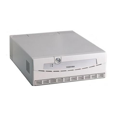
Toshiba TEC POS ST-5600 Series User manual

TEC
TEC POS Terminal
ST-5600 Series
Document No. EO1-12023A
Original Apr.; 1997
(RevisedJuly,1999)
Toshiba TEC Corporation
Table of Contents


(i)
Safety Summary EO1-12023A
Safety Summary
Personal safety in handling or maintaining the equipment is extremely important. Warnings and Cautions
necessary for safe handling are included in this manual. All warnings and cautions contained in this
manual should be read and understood before handling or maintaining the equipment.
Do not attempt to effect repairs or modifications to this equipment. If a fault occurs that cannot be rectified
using the procedures described in this manual, turn off the power, unplug the machine, then contact your
authorized TOSHIBA TEC representative for assistance.
Meanings of Each Symbol
This symbol indicates warning items (including cautions).
Specific warning contents are drawn inside the symbol.
(The symbol on the left indicates a general caution.)
This symbol indicates prohibited actions (prohibited items).
Specific prohibited contents are drawn inside or near the symbol.
(The symbol on the left indicates “no disassembling”.)
This symbol indicates actions which must be performed.
Specific instructions are drawn inside or near the symbol.
(The symbol on the left indicates “disconnect the power cord plug from the outlet”.)
Do not use voltages other than the
voltage (AC) specified on the rating
plate, as this may cause fire or
electric shock.
Any other than the
specified AC voltage
is prohibited.
WARNING This indicates that there is the risk of death or serious injury if the
machines are improperly handled contrary to this indication.
Prohibited Do not plug in or unplug the power
cord plug with wet hands as this may
cause electric shock.
Do not place metal objects or
water-filled containers such as flower
vases, flower pots or mugs, etc. on
top of the machines. If metal objects
or spilled liquid enter the machines,
this may cause fire or electric
shock.
If the machines share the same
outlet with any other electrical
appliances which consume large
amounts of power, the voltage will
fluctuate widely each time these
appliances operate. Be sure to
provide an exclusive outlet for the
machine as this may cause the
machines to malfunction.
Do not insert or drop metal,
flammable or other foreign objects into
the machines through the ventilation
slits, as this may cause fire or electric
shock.
Prohibited Prohibited
Continued use of the machines in an
abnormal condition such as when the
machines are producing smoke or
strange smells may cause fire or elec-
tric shock. In these cases, immedi-
ately turn off the power switches and
disconnect the power cord plugs from
the outlet. Then, contact your author-
ized TOSHIBA TEC representative for
assistance.
Disconnect
the plug.
If the machines are dropped or their
cabinets damaged, first turn off the
power switches and disconnect the
power cord plugs from the outlet, and
then contact your authorized
TOSHIBA TEC representative for
assistance. Continued use of the
machine in that condition may cause
fire or electric shock.
Disconnect
the plug.
Do not scratch, damage or modify
the power cords. Also, do not place
heavy objects on, pull on, or exces-
sively bend the cords, as this may
cause fire or electric shock.
(ii)
Safety Summary EO1-12023A
CAUTIONThis indicates that there is the risk of personal Injury or damage to
objects if the machines are improperly handled contrary to this indication.
If foreign objects (metal fragments,
water, liquids) enter the machines,
first turn off the power switches and
disconnect the power cord plugs from
the outlet, and then contact your
authorized TOSHIBA TEC repre-
sentative for assistance. Continued
use of the machine in that condition
may cause fire or electric shock.
Disconnect
the plug.
Do not remove covers, repair or
modify the machine by yourself. You
may be injured by high voltage, very
hot parts or sharp edges inside the
machine.
Unauthorized modification is prohib-
ited.
No
disassembling.
When unplugging the power
cords, be sure to hold and pull on
the plug portion. Pulling on the cord
portion may cut or expose the inter-
nal wires and cause fire or electric
shock.
Disconnect
the plug.
Ensure that the equipment is
properly grounded. Extension cables
should also be grounded. Fire or
electric shock can occur on improp-
erly grounded equipment.
Connect a
grounding
wire.
Precaution
The following precautions will help to ensure that this machine will continue to function correctly.
• Try to avoid locations that have the following adverse conditions:
* Temperatures out of the specification * Direct sunlight * High humidity
* Shared power socket * Excessive vibration * Dust/Gas
• Do not subject the machine to sudden shocks.
• Do not press the keys too hard. Keys will operate correctly if they are touched lightly.
• Clean the cover and keyboard, etc. by wiping with a dry cloth or a cloth soaked with detergent and wrung out
thoroughly. Never use thinner or other volatile solvent for cleaning.
• At the end of the day, turn the power OFF, then clean and inspect the exterior of the machine.
• Try to avoid using this equipment on the same power supply as high voltage equipment or equipment likely to
cause mains interference.
• USE ONLY TOSHIBA TEC SPECIFIED consumables.
• DO NOT STORE the consumables where they might be exposed to direct sunlight, high temperatures, high
humidity, dust, or gas.
• When moving the machine, take hold of the drawer and lift the machine.
• Do not place heavy objects on top of the machines, as these items may become unbalanced and fall causing
injury.
• Do not block the ventilation slits of the machines, as this will cause heat to build up inside the machines and
may cause fire.
• Do not lean against the machine. It may fall on you and could cause injury.
Request Regarding Maintenance
• Utilize our maintenance services.
After purchasing the machines, contact your authorized TOSHIBA TEC representative for assistance once per year or
so to have the inside of the machines cleaned. Otherwise, dust will build up inside the machines and may cause fire or
malfunction. Cleaning is particularly effective before humid rainy seasons.
• Our maintenance service performs the periodic checks and other work required to maintain the quality and
performance of the machines, preventing accidents beforehand.
For details, please consult your authorized TOSHIBA TEC representative for assistance.
• Using insecticides and other chemicals
Do not expose the machines to insecticides or other volatile solvents, as this will deteriorate the cabinet or other parts
or cause the paint to peel.

EO1-12023
ST-5600 OWNERS MANUAL
TABLE OF CONTENTS
Chapter Page
1. INTRODUCTION..................................................................................................................... 1
2. UNPACKING.......................................................................................................................... 2
3. FEATURES OF THE ST-5600................................................................................................ 3
4. PRECAUTIONS...................................................................................................................... 4
5. MODEL NAME DESCRIPTION.............................................................................................. 4
6. OVERVIEW............................................................................................................................. 5
7. FLOPPY DISK AND FLOPPY DISK DRIVE (with FDD Model)............................................. 7
8. UPS (Uninterruptible Power Supply) Function................................................................... 10
9. SPECIFICATIONS.................................................................................................................. 11
10.OPTION KIT............................................................................................................................ 14


- 1 -
EO1-12023
ST-5600 SERIES
EO1-12023A
ST-5600 SERIES
1. INTRODUCTION
Thank you for purchasing the TEC ST-5600 Series POS Terminal.
ThisPOSTerminalcontainsallthehighperformanceregisterfunctionnecessaryforaspecialtystorePOSTerminal
and enables the user oriented system configuration. By adopting a high-speed CPU (Pentium 133/166 MHz/AMD
K6-2266MHz),Memorywithlargecapacity(max.64MB(Pentiummodel),max.128MB(K6-2model))andmagnetic
device, this POS Terminal flexibly accepts the modification corresponding to the future system environment as the
user expects.
The ST-5600 Series, two models are available; 2 Expansion Slots Model and 4 Expansion Slots Model. The 2
Expansion Slots Model can modified into that of 4 Expansion Slots using the modification kit at customer side.
This instruction manual provides a description of the functions and handling of this terminal and should be read
carefully to obtain maximum performance. Since every consideration has been given to safety, there is no danger
of damaging the machine by incorrect operation.
Please refer to this manual whenever you have any doubts concerning the machine. This machine has been
manufactured under strict quality control and should give you full satisfaction. However, if the machine is damaged
duringtransit,orthereareanyunclearpointsinthismanual,pleasecontactyourlocalTOSHIBATECrepresentative.
• The specification described in this manual may be modified by TOSHIBA TEC, if necessary.
• Be sure to keep this manual for future reference.
• This manual presents the hardware specification of the Engine Box.
EO1-12023A
ST-5600 SERIES
(Revision Date: 7 Jul., 1999)

- 2 -
EO1-12023
ST-5600 SERIES
EO1-12023A
ST-5600 SERIES
2. UNPACKING
Confirm that the following accessories are completely contained in the carton after opening it. If some accessory is
lacking or damaged, contact the store where purchased.
1 ST-5600 Engine Box 1 Core of the ST-5600
2 FDD Cover Key 2 Used to lock and unlock the FDD cover.
3 Sub Cover 1 Attachedtothe FDDcoverwhenthesecondFDDis
installed to the expansion disk bay.
4 Bind Screw M3 x 6 6 Used to secure the sub cover.
5 Bind Unify Screw N0.6x4.5 8 Used when the disk devices (HDD and/or FDD) are
installed to the expansion disk bay.
6 Rear Cover 1 Cablecovertoput the respective cables connected
to the peripheral devises.
7 Precaution Sheet 1 CE Declaration of conformity sheet
8 Safety Maintenance Work Manual 1 Cautions on handling the product
9 Short Plug 15 Used to change the various parameters.
10 Ferrite Core 1 K6-2 model only. Attached to the LIU cable when
the LIUST-5X series is installed to the K6-2 model.
No. Part Name Quantity Remarks
2
1
4 5
3
6 7 9
8
(2 Expansion Slots model) (4 Expansion Slots model) 1
10
The power cord is not included in the carton. Please prepare it separately from a local dealer.
NOTICE
EO1-12023A
ST-5600 SERIES
(Revision Date: 7 Jul., 1999)

- 3 -
EO1-12023
ST-5600 SERIES
EO1-12023A
ST-5600 SERIES
3. Features of the ST-5600
• Equipped with a High Speed CPU
TheST-5600isequippedwithPentiumCPU(133/166MHz)orAMDK6-2(266MHz)whichprocessesdata
at a high speed.
• Installability of Memory with Large Capacity
The ST-5600 is equipped with the 8-MB memory as standard. Up to 64 MB (Pentium model) or 128MB
(K6-2 model) can be expanded by adding the optional memory board. Also, the ST-5600 is equipped
with the second cache memory of 256 KB, 512 KB as standard, therefore data processing to use
maximum performance of the CPU can be realized.
• Perfect Graphic Function
Optional VGA card enables the graphic function to display using 64 K colors with 640 x 480 pixel, or 800
x 600 pixel. Also, connecting the 10.4-inch TFT Display (TFTST-52T) enables the graphic function to dis-
play using 64K colors with 640 x 480 pixel.
• Supports the ST-5500 Compatible Mode
The ST-5600 supports the ST-5500 compatible mode to make use of software/hardware resources of
the ST-5500 obtained so far.
EO1-12023A
ST-5600 SERIES
(Revision Date: 7 Jul., 1999)

- 4 -
EO1-12023
ST-5600 SERIES
EO1-12023A
ST-5600 SERIES
4. PRECAUTIONS
1. This terminal is a precision machine. Do not subject to sudden shocks.
2. The cover should be cleaned by wiping with a dry cloth slightly dampened with a mild detergent solution.
NEVER USE THINNER OR ANY OTHER VOLATILE SOLVENT on the plastic parts.
3. DONOT POURWATER directlyontothemachineandNEVERIMMERSETHEMACHINEIN THEWATER.
4. Avoid operating the machine where it would be subject to vibration or direct sunlight.
5. Be sure to install the equipment on a flat surface.
6. The machine must be connected to a supply of the proper rated voltage.
7. Besuretousertheequipmentwithintheproperrangeofpowercurrentconsumption,temperatureandrelative
humidity.
8. Never attempt to modify the TOSHIBA TEC equipment by yourself.
5. MODEL NAME DESCRIPTION
EDO
RAM
ST - 560 - - - QM
H/W component
VGA
Card FDD HDD
NV-RAM
4None
(option) 8MB
CPU Specifications
H3: Pentium 133 MHz
H6: Pentium 166 MHz
B2: AMD K6-2 266 MHz
UPS Specifications
1: without UPS
2: with UPS
RPC
None None
None
(option)
None
(option)
None
(option)
(option)
None
(option)
None
9None
(option) 8MB None
Standard
None
(option)
USB I/F
Destination
(QM: Standard)
Pre-install OS
(Blank: without pre-install OS)
Mode
S: New Open POS Mode
C: ST-5500 Compatible Mode
Hardware Version (see NOTE)
Blank: 2-slot model (Version 1.0)
2: 2-slot model (Version 2.0)
4: 4-slot model (Version 2.0)
NOTE: Version 1: The bus mastering function is unavailable for PCI bus and ISA bus.
Version 2: The bus mastering function is available only for PCI bus.
EO1-12023A
ST-5600 SERIES
(Revision Date: 30 Nov., 1999)

- 5 -
EO1-12023
ST-5600 SERIES
EO1-12023A
ST-5600 SERIES
6. OVERVIEW
TheST-5600ENGINEBoxhasthefunctionforcontrollingallunitsconnectedtoitandforcalculationprocessingand
is the core of this system. The terminal is equipped with 3.5-inch floppy disk drive (Hardware option), 3.5-inch hard
disk drive (Hardware option).
<Front View>
NOTES: 1) The power code is not included in the carton. Please prepare it separately from a
local dealer.
2) The 3.5-inch Floppy Disk drive and 3.5-inch Hard Disk drive are optional parts for
the ST-560X-HX4XX-QM series.
(1)Power Switch
This is the switch to turn the power of the ST-5600 ON or OFF. The Power LED is illuminated when turning the
power on.
(2)3.5” Floppy Disk Drive (option)
This is the devise to read programs or write data using a 3.5-inch floppy disk.
(3)Power LED
ThisistheLED to indicatethepowerON/OFF status of theST-5600.Green LED is illuminatedwhenturning the
power ON.
(4)HDD LED
This is the LED for a model with the Hard Disk Drive installed. Green LED is illuminated during the access to the
Hard Disk Drive.
(5)FDD Cover Lock
This is the lock of the FDD cover. To lock the FDD cover, insert the FDD cover key to the FDD cover lock, then
turn it counterclockwise. To unlock the FDD cover, turn the FDD cover key clockwise.
(5) FDD Cover Lock
Power Cord (NOTE 1)
(3) Power LED
(4) HDD LED
(1)PowerSwitch
(2) 3.5” Floppy Disk Drive (option)
FDD Cover
(2 Expansion Slots model) (4 Expansion Slots model)
(5) FDD Cover Lock
Power Cord (NOTE 1)
(3) Power LED
(4) HDD LED
(1)PowerSwitch
(2) 3.5” Floppy Disk Drive (option)
FDD Cover
EO1-12023A
ST-5600 SERIES
SVO8A3008: 25 Mar., 1998

- 6 -
EO1-12023
ST-5600 SERIES
EO1-12023A
ST-5600 SERIES
<Rear View>
AC Outlet AC Inlet P24V
Mouse KB SIO1(COM4) DRW1DRW2 COM3 COM1 LPT1
( ) indicate the use for the ST-5500 Compatible Mode. Speaker
Volume
Reset
Switch
SIO2 COM4(SIO1) VGA/LCD COM2
(2 Expansion Slots model)
(4 Expansion Slots model)
EO1-12023A
ST-5600 SERIES
(Revision Date: 30 Nov., 1999)
USB 1
USB 2

- 7 -
EO1-12023
ST-5600 SERIES
EO1-12023A
ST-5600 SERIES
AC Outlet.....................a connector to the AC outlet, used for the CRT power supply.
AC Inlet .......................a connector for the AC inlet.
P24V ........................... a terminal of a DC24V line connected to the Receipt/Journal printer (DRJST-50/51 or
TRJST-52).
DRW1•2 ...................... a connector to the drawer (DRWST-50A/51A : 24V type).
MOUSE .......................a connector to the mouse. [PS/2 Type I/F]
KB ............................... a connector to POS keyboard (PKBST-50 or 51) or PC Keyboard. [PS/2 Type I/F]
COM1.......................... a PCstandard9-pinD-Subconnector(Male).Theslotscanner(LS-750orLS-770),etc.can
be connected to this connector.
COM2.......................... a PC standard 9-pin D-Sub connector (Male) as the same as COM1. The scale, cheque
printer, or Receipt/Journal printer (DRJST-50/51 or TRJST-52; Serial I/F type), etc. can be
connected to this connector.
COM3.......................... a 9-pin D-Sub connector for the serial I/F (Female). Remote indicator unit(LIUST-51), etc.
can be connected to this connector.
COM4.......................... a 9-pin D-Sub connector for the serial I/F (Female) as the same as COM3. Hand scanner
(HS-380/520; RS-232C I/F type) or front indicator unit, etc. can be connected to this
connector.
SIO1•2......................... equivalent to COM3 and COM4 (D-Sub 9-pin female).
VGA/LCD .................... a connector to the CRT (CRTST-50). See NOTE below.
LPT1............................aconnector foraPCstandardCentronics printer.Receipt/Journalprinter(DRJST-50/51or
TRJST-52; Parallel I/F type) or a printer of the parallel I/F type.
USB 1, 2...................... a connector for the USB I/F. USB Mause, USB Keyboard, etc. can be connected to these
connectors.
Speaker Volume..........Usedtoadjustthespeakervolume.Whenturnedtoleft,thesoundvolumedecreases.When
turned to right, the sound volume increases.
Reset Switch ...............Pressing this switch initializes the system.
NOTE: VGA card is not installed as standard to the model ST-560X-HX4XX-QM Series.
EO1-12023A
ST-5600 SERIES
(Revision Date: 30 Nov., 1999)

- 8 -
EO1-12023
ST-5600 SERIES
EO1-12023A
ST-5600 SERIES
7. FLOPPY DISK AND FLOPPY DISK DRIVE
(with FDD Model)
7.1 Handling the Floppy Disk
• Utilize the permanent label on the jacket.
For future reference, write on the label the date of purchase, the floppy disk ID No. for management purpose
the defective track No. (if any), etc.
• Store the floppy disks in the File Box.
Put each floppy disk in each envelope or plastic case and store it in the file box that should stand upright.
• Write on the color label with a felt pen.
When writing on the label, do not use hard-tipped writing tools such as pencils and ball-point pens. Use
something with a soft-touching tip such as a felt pen. It may cause an error to use a rubber eraser or a paper
chip.
• Do not use a damaged floppy disk.
Itwillcauseerrorstouseafloppydiskthathassurfacebeenbentorshrunken.Neverusesuchakindoffloppy
disk.
• Do not place the floppy disk close to any magnetic product.
Aproductofastrongmagnetism,suchasamagnetic paperclip,will ruinthedata recordedonthefloppydisk.
NOTE: Be careful of other magnetic products such as magnetic rings, magnetic necklaces, which will also
ruin the recorded data.
• Do not bend the floppy disk.
If bent, the floppy disk may be ruined and it will cause errors.
• Do not expose the floppy disk to a direct sunbeam.
Never put the floppy disk in a direct sunbeam or a strong heat. Infrared rays are also prohibitive.
• Keep the floppy disk away from water.
Do not wipe the floppy disk or jacket with wet cloth and alike. Do not put any water or wet thing close to the
floppy disk. Wet floppy disks will cause errors.
Head Window Shutter
Plastic Case
or
Envelope


- 11 -
EO1-12023
ST-5600 SERIES
EO1-12023A
ST-5600 SERIES
8. UPS (Uninterruptible Power Supply) Function
TheST-5602hastheUPSfunctiontoautomaticallyoperatefromtheNi-cdbatteryintheeventofapowerfailure.
When a power failure has occurred, the machine automatically switches to operate from the battery. However,
the CRT will not operate.
The thermal printer receives power from the Engine Box. Since it consumes much current, it cannot print while
theUPSoperates.Whenapowerfailureisdetected,thermalprinterprintingshouldbestoppedimmediately.Use
the function contained in the hardware to stop printing when the power failure is detected.

- 12 -
EO1-12023
ST-5600 SERIES
EO1-12023A
ST-5600 SERIES
CPU Pentium™ Processor Clock 133MHz or 166MHz
AMD K6-2 Processor Clock 266 MHz
Memory ROM 512KB BIOS (Flash ROM)
RAM 8MB (Capacity can expanded up to 64 MB (Pentium model)
or 128 MB (K6-2 model))
DRAM Type : EDO 72pin SIMM 32bit Non-parity 60ns
SIMM Socket : Four sockets (Two sockets have already been used at
shipment.)
Second Cache Memory 256KB (Pentium Model) 512KB (K6-2 Model)
Chip Set OPTi : FireStar (82C700)
VGA Controller CYBER9320 (manufactured by TRIDENT)
VIDEO Memory 1 MB as standard
VGA Controller Maximum 640 x 480, 800 x 600, 1024 x 768
Maximum number of 64K colors (640 x 480, 800 x 600)
colors 256 colors (1024 x 768)
VGA BIOS ROM 32KB
Connection to the PCI Bus
engine (Board shape is unique to TEC.)
Connection to the CRT 15-pin VGA Connector (Female)
Connection to the TFT 50-pin Half-pitch Connector (option)
Floppy Disk Drive 3.5-inch Floppy Disk Drive [720KB, 1.44MB Format] (option)
Hard Disk Drive 3.5-inch Hard Disk Drive IDE I/F (option)
Expansion Disk Bay 1 slot (However, when the above FDD and HDD are installed)
Expansion Slot 2-slot model Upto two boards or eitherISA Standard board or PCIstandard boards can
be inserted.
Board size available : Slot 2: 2/3 size(230mm) One
Slot 1: Half(180mm) One
4-slot model The boards of either ISA standard boards or PCI standard boards and two
ISA standard boards can be inserted.
Board size available : Slot 4 (highest): ISA 2/3 size (230 mm)
Slot 3: ISA 2/3 size (230 mm)
Slot 2: ISA/PCI 2/3 size (230 mm)
Slot 1 (lowest): ISA/PCI Half (180 mm)
Calendar clock Backed up by lithium battery
I/F Serial PC Standard(9-pin D-sub Male): 2ch (COM1,COM2)
For connecting the POS I/O devices (9-pin D-sub Female): 4ch
(COM3,COM4,SIO1, SIO2)
Parallel Port for a PC standard Centronics printer: (LPT1)
K/B PS/2 I/F Type: 1 ch
Mouse PS/2 I/F Type: 1 ch
Drawer 2ch:24V,Max. 2drawersofthebuilt-indrivecircuittypecanbeconnected.
Battery Life Lithium Battery: 5 years (When the TEC NV-RAM is not used.)
Ni-cd Battery: 2 years
Input Voltage (AC Inlet) 110 - 127VAC+5%-10% 50/60 Hz 3A
220 - 240VAC–10% 50/60 Hz 2A
9. SPECIFICATIONS
Item Contens
Auxiliary
Storage
Device
Graphic
Function
(NOTE)
EO1-12023A
ST-5600 SERIES
(Revision Date: 7 Jul., 1999)

- 13 -
EO1-12023
ST-5600 SERIES
EO1-12023A
ST-5600 SERIES
Item Contens
Output Voltage 110 - 127VAC+5%-10% 50/60 Hz 2A
(AC Outlet switched, for CRT) 220 - 240VAC–10% 50/60 Hz 1A
Power Consumed 180W (operating)
Ambient Temperature 5 C to 35 C
Relative Humidity 10% to 80% RH (non condensation)
Size Chassis: 2-slot model:
280mm (W) x 387mm (D) x 98.5mm (H) (excluding the cable cover)
4-slot model:
280mm (W) x 387mm (D) x 158.5mm (H) (excluding the cable cover)
Cable Cover: 280mm (W) x 80mm (D) x 98.5mm (H)
Weight 2-slot model: 8 Kg (with HDD, FDD, UPS and RPC)
6.5 Kg (without HDD, FDD, UPS or RPC)
4-slot model: 9 Kg (with HDD, FDD, UPS and RPC)
7.5 Kg (without HDD, FDD, UPS or RPC)
NOTE: VGA card for display is an optional part.
EO1-12023A
ST-5600 SERIES
SVO8A3008: 25 Mar., 1998

- 14 -
EO1-12023
ST-5600 SERIES
EO1-12023A
ST-5600 SERIES
VGAST-52-12/22-QM FDDST-51-1-QM
10.OPTION KIT
The following optional devises are available for the ST-5600 Series.
<Table of the optional devises>
FDDST-51-1-QM 2 Mode (1.44MB/720KB) 3.5-inch FDD UNIT
VGAST-52-12/22-QM VGA Card to connect the CRT or the TFTST-52T.
DRMST-52-4/8/16-QM EDO RAM Memory for expansion
NVMST-50-32/128-QM NVSRAM of 32 KB/128 KB necessary when the UPS function is used.
KITST-56-1-QM This kit was developed for converting the 2-slot ST-5600 series into 4-slot
type.
Model Name Description
NVMST-50-32/128/512-QM DRMST-52-4/8/16-QM
KITST-52-1-QM
EO1-12023A
ST-5600 SERIES
(Revision Date: 7 Jul., 1999)

- 15 -
EO1-12023
ST-5600 SERIES
EO1-12023A
ST-5600 SERIES
KITST-56-1-QM
- 15 -
EO1-12023A
ST-5600 SERIES
SVO8A3008: 25 Mar., 1998
Table of contents
Other Toshiba Touch Terminal manuals

Toshiba
Toshiba ST-B10 SERIES User manual

Toshiba
Toshiba ST-A20 SERIES User manual

Toshiba
Toshiba 4818-T10 User manual

Toshiba
Toshiba ST-71 SERIES User manual

Toshiba
Toshiba 4818-T10 User manual

Toshiba
Toshiba ST-7000-C Series User manual

Toshiba
Toshiba 4818-T10 User guide

Toshiba
Toshiba ST-B10 SERIES Operating and maintenance instructions

Toshiba
Toshiba 4818-ET1 User manual

Toshiba
Toshiba ST-A10 SERIES User manual