Toshiba TFTST-76T-5A SERIES User manual

TOSHIBA Flat Display Unit
TFTST-76T-5A SERIES
Owner's Manual

Copyright © 2006
by TOSHIBATEC CORPORATION
All Rights Reserved
570 Ohito, Izunokuni-shi, Shizuoka-ken, JAPAN
< For EU Only >
TOSHIBATEC Europe Retail Information Systems S.A.
Rue de la Célidée 33 BE-1080 Brussels
FCC Notice (for USA only)
This equipment has been tested and found to comply with the limits for a Class B digital device,
pursuant to Part 15 of the FCC Rules. These limits are designed to provide reasonable protection
against harmful interference in a residential installation.
This equipment generates, uses, and can radiate radio frequency energy and, if not installed and used
in accordance with the instructions, may cause harmful interference to radio communications.
However, there is no guarantee that interference will not occur in a particular installation. If this
equipment does cause harmful interference to radio or television reception, which can be determined
by turning the equipment off and on, the user is encouraged to try to correct the interference by one or
more of the following measures:
- Reorient or relocate the receiving antenna.
- Increase the separation between the equipment and receiver.
- Connect the equipment into an outlet on a circuit different from that to which the receiver is connected.
- Consult the dealer or an experienced radio/television technician for help.
Changes or modifications not expressly approved by manufacturer for compliance could void the
user’s authority to operate the equipment.
This Class B digital apparatus complies with Canadian ICES-003.
Cet appareil numérique de la classe B est conforme à la norme NMB-003 du Canada.
(for CANADA only)
English
The LSE0107A1240 AC adapter should be exclusively used for the TFTST-76 Series TFT.
The TFTST-76 Series TFT must be powered by the LSE0107A1240 AC adapter.
French
L’adaptateur secteur LSE0107A1240 ne doit être utilisé exclusivement que pour une TFT de type série
TFTST-76.
Les TFT dela série TFTST-76 ne doivent être alimentées que par l’adaptateur secteur LSE0107A1240.
German
Das LSE0107A1240 AC Netzteil sollte ausschließlich für den TFTST-76 Serie benutzt werden.
Der TFT TFTST-76 Serie darf nur mit den Netzteil LSE0107A1240 AC betrieben werden.
Spanish
El adaptador de corriente AC LSE0107A1240 debe de utilizarse exclusivamente para la gama de TFT
Serie TFTST-76.
La gama de TFTST-76 Serie TFTST-76 debe de utilizar el adaptador de corriente AC LSE0107A1240.
Dutch
De LSE0107A1240 AC adapter is uitsluitend bestemd voor een TFT van de TFTST-76 reeks.
Een TFT van de TFTST-76 reeks moet aangesloten worden met een LSE0107A1240 AC adapter.
Italian
L’adattatore LSE0107A1240 AC deve essere utilizzato esclusivamente per le TFT della serie
TFTST-76.
Le TFT della serie TFTST-76 devono essere alimentate tramite l’adattatore LSE0107A1240 AC.
Portuguese
O transformador AC LSE0107A1240 deve ser usado exclusivamente nas TFT da Série TFTST-76.
ATFT de Série TFTST-76 deve ser ligada através do transformadorAC LSE0107A1240.
Disposal of fluorescent lamp:
The fluorescent lamp in the TFT monitor contains mercury. Follow local ordinances or regulations for
disposal.
N258
EO1-19041
CAUTION!
1. This manual may not be copied in whole or in part without prior written permission of
TOSHIBA TEC.
2. The contents of this manual may be changed without notification.
3. Please refer to your local Authorised Service representative with regard to any queries you
may have in this manual.
TABLE OF CONTENTS
Page
Usage Notice
Precautions------------------------------------------------------------------------------------------------------------- 1
Introduction
About the Product----------------------------------------------------------------------------------------------------- 2
Package Overview---------------------------------------------------------------------------------------------------- 3
Installation
Product Overview----------------------------------------------------------------------------------------------------- 4
VESA Mount on your monitor-------------------------------------------------------------------------------------- 6
Cable Management -------------------------------------------------------------------------------------------------- 7
Start your Installation------------------------------------------------------------------------------------------------- 8
User Controls
Front Panel Controls ------------------------------------------------------------------------------------------------10
How to Use the OSD Menus--------------------------------------------------------------------------------------11
On-Screen Display Menus-----------------------------------------------------------------------------------------12
Magnetic Card Reader (Option)
How to Read a Magnetic Card -----------------------------------------------------------------------------------13
General Maintenance
Cleaning----------------------------------------------------------------------------------------------------------------14
Appendices
Troubleshooting ------------------------------------------------------------------------------------------------------15
Warning Signal -------------------------------------------------------------------------------------------------------16
Product Dimensions-------------------------------------------------------------------------------------------------17

Usage Notice EO1-19041
Precautions
1
Usage Notice
Warning-To prevent the risk of fire or shock hazards, do not expose this product to rain or moisture.
Warning-Please do not open or disassemble the product as this may cause electric shock.
Precautions
Follow all warnings, precautions and maintenance as recommended in this user’s manual to maximize
the life of your unit.
Do:
Turn off the product before cleaning.
Use only a dry soft cloth or clean room wiper when cleaning the LCD Display screen surface.
Use a soft cloth moistened with mild detergent to clean the display housing.
Use only high quality and safety approved AC/DC power adapter.
Disconnect the power plug from theAC outlet if the product is not going to be used for an extended
period of time.
Don’t:
Do not touch the LCD Display screen surface with sharp or hard objects.
Do not use abrasive cleaners, waxes or solvents for your cleaning.
Do not operate the product under the following conditions:
-Extremely hot, cold or humid environment.
-Areas susceptible to excessive dust and dirt.
-Near any appliance generating a strong magnetic field.
-Place in direct sunlight.

Introduction EO1-19041
About the Product
2
Introduction
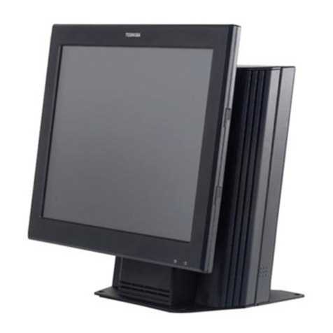
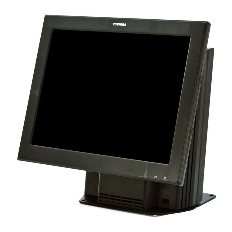
Thank you for purchasing the TOSHIBA TFTST-76T-5A Series 15-inch TFT Display Unit.
This display unit has been developed exclusive to the TOSHIBA ST-7000 and ST-6501-C7 series POS
terminal. The display unit is equipped with a touch screen panel which adopts a high-luminance type
colour LCD (15-inch TFT, 1024x768dots, 16.2 million playable colours).
The display unit provides a wide viewing angle, and is equipped with the tilt mechanism that is freely
adjustable in a range of 0° to 90°. And the touch panel provides easy operation for order entry by the
graphical user interface.
This manual contains general set-up and maintenance information and should be read carefully to help
gain maximum performance and life from your display unit. For most queries please refer to this
manual and keep it safe for future reference.
About the Product
This is a 15” flat panel screen with an active matrix, thin-film transistor (TFT) liquid crystal display
(LCD), this product also demonstrates the following outstanding features.
Direct Analog signal input
Active matrix TFT LCD technology
1024x768 XGAresolution
15” diagonal screen size
31.5 ~ 60 kHz horizontal scan
56 ~ 75 Hz high refresh rate
VESA wall mountable, removable base for flexible mounting solutions
Auto Adjustment function
Multilingual OSD user controls
VESA DPMS power saving
Built-in speakers for multimedia application
Resistive type touch screen
Kensington security slot

Introduction EO1-19041
Package Overview
3
Package Overview
LCD Display Power Adapter VGA Signal Cable
RS232 Cable
(For Touch Screen) Audio-in Cable
User’s Manual

Installation EO1-19041
Product Overview
4
Installation
Product Overview
Front View
Back View
Connector Ports (Inside the back cover)
DC
Power-In VGA
input Audio-in RS232
Liquid Crystal
Display (LCD
Display)
Panel Controls
Stand
Magnetic Card Reader (Option)

Installation EO1-19041
Product Overview
5
Tilt
Turn the knob and grasp the LCD display with both hands to adjust the tilt as desired.
Kensington Security slot
The monitor can be secured to your desk or any other fixed object with Kensington lock security products.
Kensington lock is not included.
Tilt Angle:0°~90°
Knob
Kensin
g
ton Securit
y
Slot

Installation EO1-19041
VESA Mount on your monitor
6
VESA Mount on your monitor
This monitor conforms to the VESA Flat Panel Mounting Physical Mounting Interface Standard which
defines a physical mounting interface for flat panel monitors, and corresponding standards for flat
panel monitor mounting devices, such as wall and table arms. The VESAmounting interface is located
on the back of your monitor.
The VESA Mounting slots of this model are located inside the rear cover (shown in the following
figure).
To mount the monitor on a swing arm or other mounting fixture, follow the instruction included with the
mounting fixture to be used.
Warning!
Please select the proper screws!
The depth from plastic back cover to the bottom of the screw hole is 4.2 mm. The spec is M4 screw.
VESA
Mounting
Interface
Slots
75mm
75mm

Installation EO1-19041
Cable Management
7
Cable Management
Please follow the instruction to do cable management.
1. Please pull all the cables backward while the tilt angle is 0°.
2. Please pull all the cables forward while the tilt angle is 90°.

Installation EO1-19041
Start Your Installation
8
Start Your Installation
Connecting the Display(Figure 10.1)
To setup this display, please refer to the following figure and procedures.
1. Be sure all equipment is turned off.
2. Connect the DC power cord to the power connector; plug one end of theAC power cord into the
power adapter, and the other end into an electrical outlet (n).
3. For the PC with Analog output: Connect the VGAsignal cable from display VGAinput connector
to the 15-pin connector of your host computer and tighten the screws (Y).
4. Connect the Audio-In cable from audio input port of your display to theAudio-out port of your
computer (Z).
5. Connect the RS232 cable from RS232 port of your display to the RS232 port of your
computer([).
6. Turn on your computer, display and video source.
Figure 10.1
Notice: To ensure the LCD Display will work well with your computer, please configure the display mode of your graphics
card to make it less than or equal to 1024 x 768 resolution and make sure the timing of the display mode is
compatible with the LCD screen. We have listed the “Compatibility Modes” of this LCD screen in appendices for your
reference.
XPower Cord YVGA Cable ZAudio-In
Cable
[RS232 Cable
ST-7000-WM-2E
ST-7000-WM-1C
ST-6501-C7

Installation EO1-19041
Start Your Installation
9
When connecting the TFTST-76 to the ST-7000-WM-2E
TFTST-76 ST-7000-WM-2E Rear View
VGA VGA
RS-232C COM1 or COM2
(*1)
Audio-In Line-out
MCR USB0 to USB4
*1: COM1 or COM2 is provided as a touch panel interface.
When connecting the TFTST-76 to the ST-7000-WM-1C
TFTST-76 ST-7000-WM-1C Rear View
VGA VGA
RS-232C COM1 or COM2
(*1)
Audio-In Line-out (*2)
(option)
MCR USB (*3)
(option)
*1: COM1 or COM2 is provided as a touch panel interface.
*2: ST-7000-WM-1C is not equipped with the Line-out connector as standard.
Please install an option KIT-7000-PUSB-QM-R into the POS terminal if necessary.
*3: ST-7000-WM-1C is not equipped with the USB connector as standard.
Please install an option KIT-7000-PUSB-QM-R into the POS terminal if necessary.
When connecting the TFTST-76 to the ST-6501-C7
TFTST-76 ST-6501-C7 Rear View
VGA VGA
RS-232C COM1 or COM2
(*1)
Audio-In Not available
MCR USB1 or USB2
*1: COM1 or COM2 is provided as a touch panel interface.
Line-out
Powered USB
USB0 USB1 USB2 USB3
(12V-1) (12V-2) (12V-3) (24V)
VGA USB4
Powered USB (12V)
(Option) Powered USB (24V)
(Option)
VGA Line-out
(Option)
USB1, 2 VGA
COM1
COM2
COM1
COM2
COM1
COM2

User Controls EO1-19041
Front Panel Controls
10
User Controls
Front Panel Controls
No / Icon Control Function
XPower Switch To switch on/ off the power to the LCD Display.
YPower LED 1. Green indicates the display is turned on.
2. Amber indicates the display is in power-saving
mode.
ZSSelect/Auto
Select- To select the adjustment items from OSD
menus.
Auto- To activate the “Auto Adjustment” function to
obtain an optimum image.
[┿Plus/Brightness 1.Increase value of the adjustment items.
2.Adjust the brightness of image.
\━Minus/Mute On/Off 1.Decrease value of the adjustment items.
2.Make the volume function ineffective/effective.
]MMenu Button Display the OSD menus.
X
Y
Z
[
\
]

User Controls EO1-19041
How to Use the OSD Menus
11
How to Use the OSD Menus
1. Press the "MENU" button to pop up the “on-screen menu” and to select among the four Main
Menus.
2. Choose the adjustment items by pressing the “Select/Auto” button.
3. Adjust the value of the adjustment items by pressing the “+”or “-“ button.
4. Once you don’t operate the OSD menus after a pre-set time, the OSD menus will automatically
disappear.

User Controls EO1-19041
On-Screen Display Menus
12
On-Screen display Menus
Main Menu Menu Level 2 Function Description
Auto-Adjustment Choose this function to obtain an optimum image.
Contrast Adjusts the contrast of the display image.
Brightness Adjusts the brightness of the image.
Horizontal Position Changes the horizontal position of the image.
Vertical Position Changes the vertical position of the image.
Clock Changes the displays data frequency to match the frequency of
your graphics card. When you experience a vertical flickering bar,
use this function to make an adjustment.
Page 1
Phase Synchronizes the signal timing of the display to that of the
graphics card. When you experience an unstable flickering image,
use this function to make an adjustment.
Display Mode Selects this function to demonstrate the display resolution,
vertical refresh, and horizontal scan of the current mode. .
OSD Off-Time Adjusts the time period for OSD menu to disappear.
Language Chooses the language you need.
Sharpness Adjusts the sharpness of the image.
Page 2
Reset Returns the display parameters of the current mode to its factory
default settings.
Volume It allows you to control the volume sound.
Page 3 Mute It allows you to disable the sound immediately.
Color Setting Adjusts the color temperature.
Color Adjustment-Red It allows you to adjust the red color of the display.
Color Adjustment-Red It allows you to adjust the green color of the display.
Page 4
Color Adjustment-Red It allows you to adjust the blue color of the display.

Magnetic Card Reader (Option) EO1-19041
How to Read a Magnetic Card
13
Magnetic Card Reader (Option)
Warning!
Do not apply too much pressure onto the card reader or lean against it. Doing so may damage it.
The MCRST-76-55K series optional magnetic card reader can be installed to the right side of the
TFTST-76-5A. These card readers read track 1, 2 and 3 magnetic cards which comply with ISO.
How to Read a Magnetic Card
Insert the magnetic card into the upper portion of the magnetic card reader slot and move the card
downward slowly.
Notice: Moving the magnetic card too fast or too slowly may cause a read error.
Card
MCR Unit
Portion pf the Magnetic card Reader

General Maintenance EO1-19041
Cleaning
14
General Maintenance
Cleaning
Warning!
1. Be sure to disconnect the power cord of the POS terminal prior to performing any maintenance.
2. Do not pour water directly on or wipe the LCD with a soaked cloth, as this may cause fire, electric
shock, or machine failure.
3. Never use a solvent like thinners or benzene for cleaning. Using such solvents may discolor the
covers.
4. Do not use any sharp object to clean the LCD display. Doing so may cause an LCD display failure.
5. Do not insert nozzle of an air blower into the magnetic card reader slot. Doing so may damage the
scanning head, resulting in the magnetic card reader failure.
To help retain the high quality and performance of your machine, it should be cleaned regularly. The
greater the usage on the machine, the more frequent the cleaning. (i.e. low usage = weekly ; high
usage = daily)
zCleaning the LCD
Clean the surface of the LCD display with a soft dry cloth or with an electrostatic free cleaner for
automated office equipment.
zCleaning the Covers
Wipe the covers with a soft dry cloth or soft cloth slightly moistened with mild detergent. After
using detergent for cleaning, be sure to wipe it off with a slightly moistened cloth.
zCleaning the Magnetic Card Reader
Remove any dust from the slot of the magnetic card reader with an air blower. To clean the card
reader head, use a head cleaning card available on the market.

Appendix EO1-19041
Troubleshooting
15
Appendix
Troubleshooting
If you are experiencing trouble with the LCD display, refer to the following trouble shooting. If the
problem persists, please contact your local dealer or our service center.
Problem: No image appears on screen.
Check that all the I/O and power connectors are correctly and well connected as described in the “Installation”
section.
Make sure the pins of the connectors are not crooked or broken.
Problem: Partial Image or incorrectly displayed the image.
Check to see if the resolution of your computer is higher than that of the LCD display.
Reconfigure the resolution of your computer to make it less than or equal to 1024 x 768.
Problem: Image has vertical flickering line bars.
Use "Clock" to make an adjustment.
Check and reconfigure the display mode of the vertical refresh rate of your graphic card to make it compatible
with the LCD display.
Problem: Image is unstable and flickering
Use "Phase" to make an adjustment.
Problem: Image is scrolling
Check and make sure the VGA signal cable (or adapter) is well connected.
Check and reconfigure the display mode of the vertical refresh rate of your graphics card to make it compatible
with the LCD Display.
Problem: Vague image (characters and graphics)
Use "Clock" to make an adjustment. If this problem still exists, use “Phase” to make an adjustment.
Table of contents
Other Toshiba Touch Terminal manuals

Toshiba
Toshiba ST-B10 SERIES Operating and maintenance instructions

Toshiba
Toshiba ST-A20 SERIES User manual

Toshiba
Toshiba 4818-T10 User guide

Toshiba
Toshiba 4818-T10 User manual

Toshiba
Toshiba 4818-T10 User manual

Toshiba
Toshiba ST-B10 SERIES User manual

Toshiba
Toshiba ST-7000-C Series User manual

Toshiba
Toshiba ST-7000 Series User manual

Toshiba
Toshiba TEC POS ST-5600 Series User manual

Toshiba
Toshiba 4818-ET1 User manual