manuals.online logo
Brands
  1. Home
  2. •
  3. Brands
  4. •
  5. TouchTunes
  6. •
  7. Jukebox
  8. •
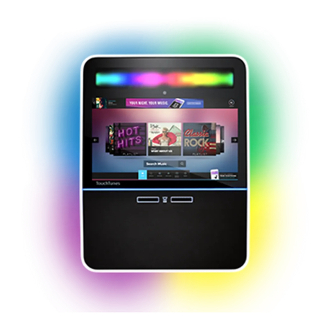
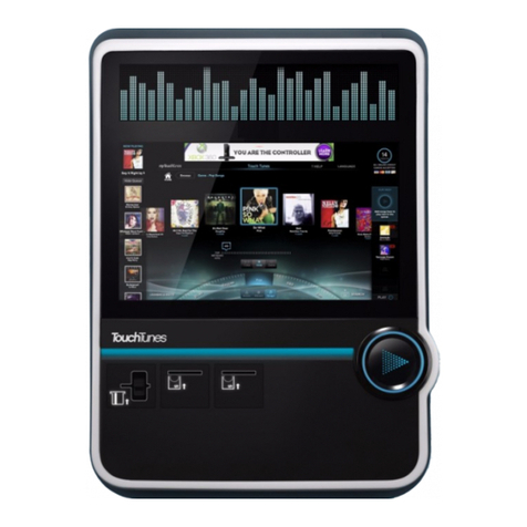
  9. TouchTunes Playdium User manual

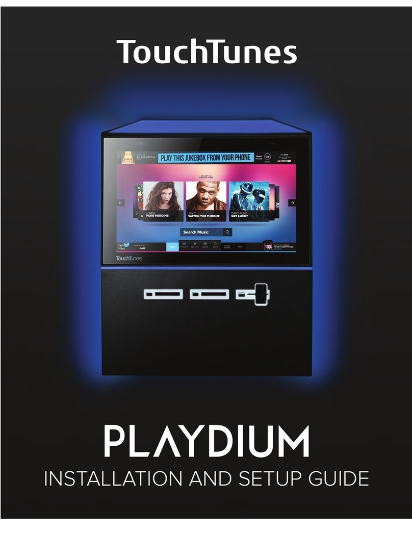
TouchTunes Playdium User manual

900785-001 Rev. 02 February 2016
This guide is an overview of the Playdium installation process.
1 of 12
Quick Start Guide
Disclaimer and Important Safety Instructions
TouchTunes Interactive Networks is not responsible for
any damage resulting from the improper installation or
connection of test kit components or any other external
equipment to Playdium. Nor is TouchTunes responsible for
anydamagecausedduringshipment(excepttheshipment
to the original purchaser) or any damage caused by:
•impacts, fluids, fire, flood, wind, earthquake, lightning
or similar disaster
•unauthorized modifications, attachments or
peripherals, improper use, environment, installation or
electrical supply
•improper maintenance
•any other misuse, abuse, or mishandling
Familiarize yourself with this important safety information
before proceeding with product installation.
The Lightning Flash with arrow head symbol
within an equilateral triangle is intended to alert
the user to the presence of un-insulated
"dangerous voltage" within the product enclosure
that may be of sufficient magnitude to constitute a
risk of shock to persons".
The exclamation point within an equilateral
triangle is intended to alert the user to the
presenceofimportantoperatingandmaintenance
(servicing) instructions in the literature
accompanying the product".
WARNING: Do not defeat the safety purpose of
the polarized or grounding-type plug. A polarized
plug has two blades with one wider than the other.
A grounding type plug has two blades and a third
grounding prong. The wide blade or the third
prong are provided for your safety. If the provided
plug does not fit into your outlet, consult an
electrician for replacement of the obsolete outlet.
WARNING:TOREDUCETHE RISKOF FIRE OR
ELECTRIC SHOCK, DO NOT EXPOSE THIS
APPARATUS TO RAIN OR MOISTURE AND
OBJECTS FILLED WITH LIQUIDS, SUCH AS
VASES, SHOULD NOT BE PLACED ON THIS
APPARATUS
DO NOT USE THISAPPARATUS NEAR WATER.
WARNING:TOREDUCETHE RISKOF FIRE OR
ELECTRIC SHOCK, THISAPPARATUS SHALL
BE CONNECTED TO A MAINS SOCKET
OUTLET WITH A PROTECTIVE EARTHING
CONNECTION.
WARNING: The speaker output of this unit can
exceed 10 Watts and could cause a shock injury.
Connectiontospeakersshouldbe performed by a
skilled person in compliance with local building
codes. Class 2 wiring is required for speaker
cables. Use of external speakers outside the
ratings stated at the speaker jack may result in a
shock injury or damage to the unit, or equivalent.
CAUTION: Playdium is heavy and represents a
serious safety hazard if its mounting system
should fail. Installation of the mounting system for
Playdium should be performed only by an
experienced installer or licensed contractor
familiar with standard rigging, mounting and
hanging practices as recognized by a licensed
engineer or government agency in your area.
Playdium is intended to be wall mounted or used
only with TouchTunes Floor Stand model 700748-
001, which is optional.
CAUTION:DonotusePlaydiumimmediatelyafter
transferring the unit from a cold place to a warm
place as condensation may have occurred on
internal components. Wait for the unit to reach
room temperature before using it.
IMPORTANT: See product enclosure for safety-
related markings.
TO COMPLETELY DISCONNECT THIS
APPARATUS FROM THEAC MAINS,
DISCONNECT THE POWER SUPPLY CORD
PLUG FROM THEAC RECEPTACLE
THE MAINS PLUG OF THE POWER SUPPLY
CORD OR APPLIANCE COUPLER SHALL
REMAIN READILY ACCESSIBLE
No serviceable parts inside the core, please
contact TouchTunes Customer Support for
service; only the hard drive is designed to be
serviced, and is accessible from outside the core.
2 of 12
Before You Begin:
Activation of Playdium requires a broadband Internet
connection. If you do not have access to a working
Internet connection, do not attempt installation and setup
of Playdium, as you will not be able to complete the
process.
Step 1: Move the carton as close as possible to
the intended mounting location
Move Playdium while it is still in its packaging.
DO NOT SLIDE OR DRAG THE UNCRATED PLAYDIUM
ALONG THE FLOOR!
Step 2: Unpack Playdium
Carefullyopenthepackaging,andremovethe foamforms
that protect the jukebox.
Step 3: Determining Where Playdium Will Be
Installed
Important: When installing in a location where there is an
intersecting wall to the right, ensure that you allow at least
10 inches of clearance between the wall and Playdium to
allow easy access to the lock mechanism.
1. On the wall where Playdium is to be installed,
measure 68 inches (5’ 8”) from the floor and mark this
measurement. This will indicate where the top of the
jukebox chassis needs to go.
Important: Additional electrical and safety requirements
appear on the Playdium Product Label located at the
bottom of the rear enclosure, behind the payment door.
• Read these instructions.
• Keep these instructions.
• Heed all warnings.
• Follow all instructions.
Clean only with dry cloth.
Do not block any ventilation openings. Install in
accordance with the manufacturer’s instructions.
Do not install near any heat sources such as
radiators, heat registers, stoves, or other
apparatus (including amplifiers) that produce
heat.
Protect the power cord from being walked on or
pinched particularly at plugs, convenience
receptacles, and the point where they exit from
the apparatus.
Only use attachments/accessories specified by
TouchTunes.
Unplug this apparatus during lightning storms or
when unused for long periods of time.
Refer all servicing to qualified service personnel.
Servicing is required when the apparatus has
been damaged in any way, such as power-supply
cordorplugisdamaged,liquidhasbeenspilledor
objects have fallen into the apparatus, the
apparatus has been exposed to rain or moisture,
does not operate normally, or has been dropped.
3 of 12
2. Using the included template, mark the position for the
chassis on the wall where you intend to install
Playdium, ensuring that the template is leveled.
3. Mark where the screws will be inserted. The top two
holes should be aligned with the top part of the
mounting slot in the chassis, so that the chassis will
“hang” from those two screws, while the bottom two
holes should be aligned with the bottom of the
mounting slots, to make it harder to pull Playdium up
and off its screws without first removing the bottom
screws.
4. Partially install the top two screws on the markings
you just made. You will soon be hanging Playdium on
those two screws.
If installing on drywall or concrete, use wall anchors
designed to support at least 50lbs each, then fasten
the chassis to the wall by inserting the screws through
the holes in the chassis, and into the anchors.
5. With the Playdium lying on its back, and using the
provided key, unlock the payment panel and open it to
reach the lever below the core.
6. Pull the pin that keeps the lever from moving (A).
Then, while still pulling on the pin, pull the lever down
(B) to pop the core out of its connectors (C).
7. Lift the core, and carefully set it aside (on a table or
counter) in the orientation shown below.
8. Lift the chassis and bring it up to the wall, hanging it
on the two screws you just installed.
Note: Playdium MUST be mounted vertically when
docking the core. Do not attempt to dock the core while
the chassis is not mounted vertically. Failure to do so
could damage the core or the chassis.
Minimum 10”
from wall
37.5”
from oor
30.5”
23.5”
Floor
68”
Key
A
B
C
4 of 12
9. Fully fasten the chassis to the wall using four (4) extra
screws, and tighten the two screws already installed.
Step 4: Install the Hard Drive
10.Follow proper grounding procedure before handling
the hard drive. Failure to do so could lead to static
discharge and damage to the hard drive.
11.Locate the hard drive.
The hard drive and its enclosure are shipped
separately from the main Playdium hardware.
12.Align the hard drive enclosure with its slot on the
underside of the core.
13.Insert the hard drive enclosure in the slot and then
gently push the enclosure in until it is completely
seated.
14.Using your fingers, push in and then tighten the thumb
screw (clockwise) on the hard drive tray until the
thumb screw is securely tightened.
15.Test whether the hard drive is firmly seated by pulling
out firmly on the handle of the hard drive tray.
The hard drive is secured properly when:
•The spring on the thumb screw is completely
compressed and covered by the cowl head of the
thumb screw.
•There is no gap between the edge of the hard drive
tray and the computer.
•There is no play between the hard drive and the
computer when you pull outward on the handle of the
hard drive tray.
5 of 12
Step 5: Access the Cable Channels
Playdium is designed with two cable channels that let you
route outside cables into the jukebox.
Note: Route cables into and out of Playdium only through
the provided cable channel openings. Do not route
cables through any other openings in Playdium, such as
air vents.
Thebottom cable channel ismore readily accessible, soit
will mean less work if you can run all cables through the
bottom channel.
To access the top cable channel, you must first unfasten
the airflow assembly and pull it out of place. The airflow
assembly is held in place by two hooks and four screws.
1. To remove theAirflow Assembly, first loosen the four
screws until they are no longer pushing against the
metal of the chassis.
2. Now that the assembly is loose, push the back part up
to unhook it from the chassis, then pull the assembly
out.
3. Lay the airflow assembly down on the middle support
bar.
4. Loosen the screws that hold the strain relief bracket in
place, and slide the bracket down.
5. Route any cables that need to be routed through the
top cable channel. The cables should be routed along
the middle of the bracket, and laid as flat as possible.
6 of 12
6. Verify that there is enough slack in the wires as you
connect them to the backplane.
7. Push the strain relief bracket back up, and tighten its
screws to hold it in place.
8. Use a zip tie to tie the wires to strain-relief bracket.
This will make it easier to reinstall the airflow
assembly.
9. Hook the Airflow Assembly back into position on the
chassis.
10.You will have to slide the left side in first, and behind
the cable for the top lighting panel.
11.Tighten the four screws until they push against the
metal of the chassis, such that the assembly cannot
be moved any longer (with the exception of the middle
flap.) The screws do not need to go in all the way;
they only need to push up against the chassis.
Note: The airflow assembly should not be disconnected,
unless you are replacing a damaged assembly. The
airflow assembly is required to maintain the temperatures
inside Playdium at acceptable levels.
To route cables through the bottom cable channel, loosen
the screws that hold its strain-relief bracket and slide it
until you can run your cables through. Remember to slide
the cover back into place and tighten its screws again
whenyou are done.Alsorememberto leave enoughslack
on the cables to avoid any strain on the cables and
connectors.Finally, tighten the screws on the bracket to
hold it in place.
Step 6: Connect Playdium to the Broadband
Network
1. Locate the RJ-45 Ethernet cable for the broadband
connection.
2. Connect either end of the cable to a broadband
modem or router.
3. Route the free end of the cable into Playdium through
a cable channel.
4. Connect the free end of the cable to the port labeled
LAN on the backplane.
You will later configure the communications settings for
the broadband network so Playdium can contact the
TouchTunes server using this connection.
Step 7: Connect Audio Speakers to Playdium
1. Prepare your speaker wires by stripping the ends of
the 4 connector wires, exposing approximately 1/4” of
wire.
2. Locate the supplied four-slot Euroblock connector.
3. Loosen the screws along the
top of the connector using a
flat-head screwdriver, if
necessary.
4. Wire the ends of the speaker
wires to the Euroblock
connector using the figure
above as a guide.
5. Tighten the screws of the
slots to secure the speaker
cable to the connector. Speaker Wiring
6. Insert the Euroblock connector into the connector
labeled Zone 1 or Zone 2 on the backplane.
Note: There are two connectors for each zone. These
connectors are wired in parallel. For more on how to wire
different sets of speakers, refer to the connection
diagram poster (packaged along with this guide.)
7. Route the free end of the cables out of Playdium
through the appropriate cable channel.
8. Connect the other end of the cables to the speakers,
ensuring that proper polarity is respected. Incorrect
connection can result in poor imaging and thin sound.
LEFT TOP
SIDE LIGHT
VOLUME PCB
SPEAKERS
R
-+
L
+-
ZONE
2
SPEAKERS
R
-+
L
+-
ZONE
1
CLASS 2 WIRING
CLASS 2 WIRING
7 of 12
Step 8: Tighten the Bottom Strain Relief Bracket
1. Pull in and hold a short length (1 - 2 inches) of each
cable running through the cable channel to ensure all
cables in Playdium have some slack.
2. The wire-strain relief bracket should already have
been loosened when you ran cables through the cable
channel.Adjust the wire-strain relief bracket until both
of the following conditions are met:
•The bracket presses against and holds all of the
cables coming into Playdium through the cable
channel to maintain slack for each cable.
•The bracket partially closes the cable channel
opening to Playdium to prevent dust from entering the
Playdium.
3. Tighten the screws for the wire-strain relief bracket to
hold the bracket in position.
Step 9: Install the Core
1. Bring the core close to the mounting location.
2. Ensure that the red lever on the chassis is pulled
down and vertical, ready to receive the core.
3. Lift the core, and position on the chassis, above the
red lever.
4. While holding the core in the chassis, pull the pin that
holds the red lever in position, and then carefully
move the red lever up.
5. Once you’ve moved the lever enough, the pin will stay
up. Release it, and use that hand to push the core into
the chassis, while pushing the red lever up.
6. As you push the red lever up, the core will go down.
When the red lever reaches horizontal, the core will
be in its final position, and the pin will snap into place.
Step 10: Power Up Playdium
CAUTION: Donotpower up Playdium immediately
after transferring the unit from a cold place to a
warm place as condensation may have occurred
on internal components. Wait for the unit to reach room
temperature before using it.
1. Connect theAC power cord from the rear of Playdium
to a properly-grounded (3-prong) electrical outlet.
CAUTION:Donotover-torquethescrews.Doing
so can damage the bracket, hampering it from
sliding smoothly, later, when you next adjust it.
8 of 12
2. Set the power rocker switch on the Playdium’s power
strip to ON.
Step 11: Close the Payment Panel
1. Close the Playdium payment panel by gently pulling it
up and shut, then pressing on its front face to engage
the locking mechanism.
2. Secure the payment panel by using the key to lock its
case.
Step 12: Enable the Screen
When you power up Playdium for the first time, it
automatically goes into night mode: the computer and
other internal components of Playdium are running, but
thetouchscreen, audiosystemand lightsforPlaydiumare
disabled.BringPlaydiumoutofnightmodeandactivateits
screen before setting it up.
Thisisdonebypressingthepowerbuttononthebottomof
the jukebox.
When you press this button, the touchscreen, lights and
audio system for Playdium are activated.
The Software initialization screen appears indicating that
Playdium is starting the installation process.
You can now use the touch screen to activate Playdium
and configure its settings using the system software.
Follow the prompts on the screen to complete activation.
Step 13: Activate Playdium
WARNING: Booting the system can take up to ten
(10) minutes, and the screen can be blank for up to 90
seconds during the installation procedure.
It is extremely important that you do not power down
or attempt to reboot Playdium during this procedure,
or you risk corrupting and rendering the hard drive
unusable.
ActivatingPlaydium involves calibratingthe touch screen,
and configuring its settings by following the on-screen
instructions.
Calibrate the Touch Screen
After the software installation process completes, the first
calibration screen appears.
Initial Settings
In the settings screens, you select the settings for
Playdium, such as primary language, calling window and
type of broadband connection.
Afteryou specify the settings,aCommunicationsNetwork
status lights indicator with activity messages appears.
What the network status lights indicate:
•Local Ethernet: whether an ethernet cable is properly
connected to the jukebox, and the jukebox is receiving
a signal from it.
•Host Resolving: whether the jukebox is connected to
the internet.
•Logged In: whether the jukebox is logged into the
TouchTunes server. The jukebox must be able to log
into the TouchTunes server to receive activation
information and perform transactions, such as
returning daily sales information.
•Music Access: whether the jukebox can access
music from the TouchTunes server. The jukebox must
have music access to download new songs.
9 of 12
•Data Access: whether the jukebox can communicate
with TouchTunes server to receive updates from the
TouchTunes Dashboard. The jukebox must have data
access to receive any new settings you may have
made to it via the TouchTunes Dashboard.
For installation and activation, the jukebox needs the
Logged In, Music Access and Data Access indicators to
be green.
When the jukebox is fully initialized, theAttract Screen of
the Customer Interface appears.
Step 14: Call Now
After you activate Playdium, ensure you perform a “Call
Now”so that yourjukeboxisequippedwith the most up-to-
date software.
To do this, access the Diagnostics menu of the Operator
Interface.
1. Locate the Manager button on the backplane.
2. Press and release the Manager button.
Playdium displays the Operator main menu.
3. From the Main menu, select the Diagnostic button.
4. Press the Call now button at the bottom of the menu.
Playdium communicates with the TouchTunes servers
and downloads the most recent software build.
Step 15: Set Up the Remote Control
Theremote control is poweredby two 1.5VAAAbatteries.
Insert the batteries in the compartment on the rear of the
remote. Use only high-quality alkaline batteries.
By default, the remote control ID is set to 000. To change
the remote control ID:
LAN
USB
12 3
4
USB
5
PAYMENT
LIGHT
DOOR
SWITCH
COIN
ACC
BILL
ACC
SERIAL
1
EXT. LIGHT
12 3
AUDIO IN
2 1 3
AUDIO OUT
MIC 1 AUX
SPK
2
3
&
4
1
&
2
RF REMOTE
LEFT TOP
SIDE LIGHT
VOLUME PCB OPTION 2
RIGHT
SIDE LIGHT
OPTION 2
ID MODULE
MNGR
R
-+
L
+-
ZONE
2
SPEAKERS
R
-+
L
+-
ZONE
1
CLASS 2 WIRING
CLASS2WIRING
Use the mounting bracket to install
the remote control on a wall for easy
access.
Fasten the bracket to the wall with
two screws as illustrated.
10 of 12
1. Press the POWER and F4 keys at the same time and
hold them down until the red indicator light blinks two
times.
2. Enter the new three-digit code to use. The new code
must be in the range 000 to 255.
3. The red indicator light will light up for three seconds to
confirm your selection. If you enter an invalid code the
light will blink five times.
Learn the Remote ID
1. On the Operator Interface, open the Hardware
Options screen.
2. Press the LEARN button.
3. Watch the display. When prompted, press the MIC
VOL UP key on the remote control.
The screen displays a success message and returns
to the Options screen.
4. Test the remote by raising and lowering the jukebox
volume as it is playing.
Pressandhold
to set remote
control ID.
Pre-programmed Remote Control Keys
Key Function
Power Press to turn the jukebox
monitor and audio
subsystem on or off. The
jukebox computer remains
on. Equivalent to pressing
the Night Mode button on
the jukebox (not available
on all models).
Pause Pauses the jukebox.
Numeric keys - Used to program the
remote and for future use.
MIC VOL Raises and lowers the
volume of the microphone
within the limits set on the
Mixer Settings screen.
P1 Give promotional credit:
Press and release this
buttontoadda credittothe
jukebox. Credits are
deducted from the
promotional credit count.
The promotional credit
featureisenabled/disabled
on the Credit Settings
screen.
P2 For future use.
P3/Skip Skip song: Quickly press
andreleasetostopplaying
the current song and
immediately skip forward
to the next song in the
queue. The skip song
featureisenabled/disabled
on the System Settings
screen.
Flush play queue: Press
andholdthisbuttonforfour
seconds to flush the entire
play queue.
VOLUME ZONE 1, 2, 3 Raises and lowers the
volume of the selected
zonewithinthelimitsseton
the Sound Mixer screen.
F1,F2, F3, F4 For future use.
Left-arrow, right-arrow,
OK
For future use.
11 of 12
Step 16: Configure Bill Acceptors
Note: Do this procedure if you have an optional second
bill acceptor installed in Playdium.
1. On the Operator Interface, open the Hardware
Options screen.
From this menu, you can configure Playdium to use two
bill acceptors or one. By default, this option is ON.
•If your Playdium has a single bill acceptor, you must
turn this option OFF.
•If your Playdium has dual bill acceptors, you must
ensure that this option is turned ON.
Step 17: Test Payment Acceptors
To test the bill and coin acceptors
1. On the Operator Interface, open the Money >
Options screen.
2. In the COIN & BILL ACCEPTOR area, press the
TEST button.
3. Insert a bill into the bill acceptor.
The screen refreshes, showing the denomination of
the bill that was inserted, and the origin of the bill (first
or second bill acceptor).
4. For the Canadian model only, insert a coin into the
coin acceptor.
The screen refreshes, and shows the value of the
coin.
Step 18: Reapply Filters and Credit Rules
IfyouarereplacingapreviousTouchTunesjukeboxwitha
Playdium jukebox, music filters and credit rules for the old
jukebox must be reapplied to Playdium.
•To configure music filters, select the Music Operator
menu, and press the Filters button.
•To configure credit rules, select the Money Operator
menu, and press the Credit rules button.
Configure your settings as required.
Denomination
Source
Copyright © 2016 TouchTunes Music Corporation
TouchTunes Music Corporation
400 Sainte Croix Avenue, Suite 200 E
Montreal, Quebec,
Canada, H4N 3L4
TouchTunes Music Corporation
850 ThirdAve, Suite 15C
New York, NY 10022
USA
Technical Support
847-353-1954
www.touchtunes.com
A Note About Affixing Stickers to
Playdium
Playdium’s touch screen’s bezel-less design means that
the entire glass is touch-sensitive—not just the user
interfacearea—and must be keptclearof objects that can
interfere with user interaction and the proper operation of
the jukebox.
Never affix stickers, decals, or transfers to the touch
screen monitor. Doing so can adversely affect
jukebox behavior.
Camera
User
Interface
Do not affix stickers
(even partially) anywhere
on the glass or over
the camera

Other manuals for Playdium

3

Other TouchTunes Jukebox manuals

TouchTunes Playdium User manual

TouchTunes

TouchTunes Playdium User manual

TouchTunes ANGELINA User manual

TouchTunes

TouchTunes ANGELINA User manual

TouchTunes Ovation User manual

TouchTunes

TouchTunes Ovation User manual

TouchTunes Virtuo 700259-001 Assembly instructions

TouchTunes

TouchTunes Virtuo 700259-001 Assembly instructions

TouchTunes Photobooth User manual

TouchTunes

TouchTunes Photobooth User manual

TouchTunes Playdium Floor Stand Assembly instructions

TouchTunes

TouchTunes Playdium Floor Stand Assembly instructions

TouchTunes Virtuo Test Fixture User manual

TouchTunes

TouchTunes Virtuo Test Fixture User manual

TouchTunes Allegro MX-1 Quick start guide

TouchTunes

TouchTunes Allegro MX-1 Quick start guide

TouchTunes ANGELINA Assembly instructions

TouchTunes

TouchTunes ANGELINA Assembly instructions

TouchTunes Allegro MX-1v Assembly instructions

TouchTunes

TouchTunes Allegro MX-1v Assembly instructions

TouchTunes Maestro II User manual

TouchTunes

TouchTunes Maestro II User manual

TouchTunes Ovation Jukebox User manual

TouchTunes

TouchTunes Ovation Jukebox User manual

TouchTunes Playdium User manual

TouchTunes

TouchTunes Playdium User manual

TouchTunes Allegro Supplement

TouchTunes

TouchTunes Allegro Supplement

TouchTunes Virtuo Floor Stand User manual

TouchTunes

TouchTunes Virtuo Floor Stand User manual

TouchTunes Virtuo II Series User manual

TouchTunes

TouchTunes Virtuo II Series User manual

TouchTunes Playdium Assembly instructions

TouchTunes

TouchTunes Playdium Assembly instructions

Popular Jukebox manuals by other brands

Ricatech RR3100 user manual

Ricatech

Ricatech RR3100 user manual

Philips HDD060 Service manual

Philips

Philips HDD060 Service manual

Hamilton/Buhl Juke24 quick start guide

Hamilton/Buhl

Hamilton/Buhl Juke24 quick start guide

Crosley Crosley iJuke CR17 instruction manual

Crosley

Crosley Crosley iJuke CR17 instruction manual

Victrola VJB-135 instruction manual

Victrola

Victrola VJB-135 instruction manual

Philips FR-HDD060 Frequently asked questions

Philips

Philips FR-HDD060 Frequently asked questions

HQ HQ-JB100 manual

HQ

HQ HQ-JB100 manual

auna Graceland Touch manual

auna

auna Graceland Touch manual

Itek I60018CD Safety & instruction manual

Itek

Itek I60018CD Safety & instruction manual

Philips HDD17B user manual

Philips

Philips HDD17B user manual

Medion MP3 JUKEBOX manual 

Medion

Medion MP3 JUKEBOX manual 

Acesonic KOD-3000 user manual

Acesonic

Acesonic KOD-3000 user manual

manuals.online logo
manuals.online logoBrands
  • About & Mission
  • Contact us
  • Privacy Policy
  • Terms and Conditions

Copyright 2025 Manuals.Online. All Rights Reserved.