Touratech 01-048-0380-0 User manual

Diese Anleitung ist nach unserem derzeitigen Kenntnis-
stand verfasst. Rechtliche Ansprüche auf Richtigkeit
bestehen nicht. Technische Änderungen vorbehalten.
DIN EN ISO 9001:2000
Zertifikat 15 100 42285
01-048-0380-0 / 01-048-0382-0 / 01-048-0384-0 / 01-048-0386-0 /
01-048-0388-0 / 01-048-0390-0
These instructions are at our present level of
knowledge. Legal requirements for correctness do not
exist. Technical issues subject to change.
DE20080314 August 2009
Lieferumfang:
1 x Tank
1 x Tankblende links
1 x Tankblende rechts
Montagematerial:
1 x Tankdeckel abschließbar
1 x Querabstützung
1 x Tankhalter oben rechts
1 x Tankhalter oben links
2 x Halteblech Benzinleitung
1 x Schnabelhalter rechts
1 x Schnabelhalter links
2 x Verstellwinkel Schnabel (links/rechts)
2 x Distanzrohr vorne 31mm
2 x Distanzrohr hinten 37mm
1 x Zellgummi-Matte 10mm (200x200mm)
1 x Spiral-Schlauchschutz 9,5-10 1,5m
1 x Schlauch Tankentlüftung 5x2 3,5m
1 x Benzinschlauch 7,x12,5 1,5m
3 x Sechskantschraube M10x20 A2
3 x U-Scheibe M10 klein A2
8 x Gummitülle
2 x Lenkerschelle gummiert D25
2 x Linsenkopfschraube M6x20 A2
8 x U-Scheibe M8 groß A2
4 x Linsenkopfschraube M8x50 A2
2 x Mutter selbstsichernd M8 A2
9 x Kabelbinder 290mm
9 x Kabelbinder 130mm
1 x Rahmenschutzfolie 0,3m
8 x Linsenflanschkopfschraube M5x20 A2
2 x Distanz 4mm hoch POM schwarz
2 x Distanz 3mm hoch POM schwarz
6 x Linsenflanschkopfschraube M5x12 A2
9 x U-Scheibe M5 groß A2
6 x Mutter selbstsichernd M5 A2
2 x Zylinderkopfschraube M6x12 A2
6 x U-Scheibe M6 klein A2
4 x Linsenkopfschraube M6x16 vz
4 x U-Scheibe M6 klein vz
4 x Senkkopfschraube M6x20 vz
4 x Hutmutter M6 hoch vz
4 x Viton Dichtung
2 x Platte Benzinanschluss innen
2 x Platte Benzinanschluss außen
2 x Ringanschluss M12
2 x Hohlschraube M12
1 x Benzinhahn rechts
1 x Benzinhahn links
4 x Dichtring Kupfer D12mm
2 x Schnellverschluss 8mm Zapfen
2 x Schnellverschluss 8mm Kupplung
5 x Dichtring Alu D6mm
1 x Dichtring Alu D8mm
8 x Schlauchklemme 11-13mm
2 x U-Scheibe M8 klein A2
1 x Entlüftungsstutzen M8
1 x Überlaufstutzen M6
1 x Rückschlagventil Acerbis
1 x T-Verbinder
1 x Lenkererhöhung 20mm mit Montagematerial
1 x Blinkerumbau (nur bei 01-048-0390-0)
Achtung! Mehrere U-Scheiben verschiedener
Größen bleiben nach der korrekten Montage übrig.
Diese können als Distanzen zum Toleranzausgleich
verwendet werden, sollten an einigen Stellen Spalte
oder Spannungen vorhanden sein!
Anleitung: Tankumbau
BMW F800/650(Twin)GS
:
August 2009
Instructions: Tank conversion for
BMW F800/650 (Twin) GS
Supplied with:
1 x tank
1 x tank shield, left
1 x tank shield, right
Fitting materials:
1 x lockable tank cap
1 x cross support
1 x tank bracket, top right
1 x tank bracket, top left
2 x fuel line retaining plate
1 x nose bracket, right
1 x nose bracket, left
2 x nose adjustment bracket (left/right)
2 x spacer tube, front 31 mm
2 x spacer tube, rear 37 mm
1 x foam rubber mat, 10 mm (200 x 200 mm)
1 x spiral hose protector set, 9.5-10, 1.5 m
1 x tank vent hose 5x2, 3.5 m
1 x fuel hose 7.5x12.5, 1.5 m
3 x M10x20 A2 hexagon bolt
3 x small M10 A2 washer
8 x rubber grommet
2 x rubberised handlebar clamp D25
2 x M6x20 A2 oval head bolt
8 x large M8 A2 washer
4 x M8x50 A2 oval head bolt
2 x self-locking M8 A2 nut
9 x cable tie, 290 mm
9 x cable tie, 130 mm
1 x protective film for frame, 0.3 m
8 x M5x20 A2 flanged oval head bolt
2 x POM spacer, 4 mm high, black
2 x POM spacer, 3 mm high, black
6 x M5x12 A2 flanged oval head bolt
9 x large M5 A2 washer
6 x self-locking M5 A2 nut
2 x M6x12 A2 cheese head bolt
6 x small M6 A2 washer
4 x M6x16 oval head bolt, galv.
4 x small M6 washer, galv.
4 x M6x20 countersunk bolt, galv.
4 x M6 high cap nut, galv.
4 x Viton seal
2 x internal fuel connection plate
2 x external fuel connection plate
2 x M12 ring connection
2 x M12 hollow bolt
1 x fuel tap, right
1 x fuel tap, left
4 x copper sealing washer, D12 mm
2 x quick coupler 8 mm, male
2 x quick coupler 8 mm, female
5 x aluminium sealing washer, D6 mm
1 x aluminium sealing washer, D8 mm
8 x 11-13 mm hose clamp
2 x small M8 A2 washer
1 x M8 vent connection
1 x M6 overflow connection
1 x Acerbis check valve
1 x T-connector
1 x 20 mm handlebar riser with assembly kit
1 x indicator conversion (only with 01-048-0390-0)
Please note: Several washers of various sizes will be
left over after correct installation. These can be used
as spacers for tolerance compensation if gaps or
stresses are present somewhere.
See also our catalogue
or on the Internet at www.touratech.com
Sehen Sie auch in unserem Katalog
oder im Internet unter www.touratech.com

DIN EN ISO 9001:2000
Zertifikat 15 100 42285
DE20080314 August 2009 August 2009
Diese Anleitung ist nach unserem derzeitigen Kenntnis-
stand verfasst. Rechtliche Ansprüche auf Richtigkeit
bestehen nicht. Technische Änderungen vorbehalten.
These instructions are at our present level of
knowledge. Legal requirements for correctness do not
exist. Technical issues subject to change.
Montage-Vorbereitungen:
Motorrad auf Hauptständer abstellen!
Entfernen Sie Schnabel, Schnabel-Seitenteile,
Airboxcover, Airbox-Seitenverkleidungen und
Sitzbank! Ebenfalls entfernen müssen Sie die
beiden kleinen Seitendeckel am Hauptrahmen
links und rechts! Windschild oder Desierto F
Verkleidung montiert lassen, diese benötigen Sie,
um Die Schnabelhalter ausrichten zu können!
Benzin aus dem Hecktank vollständig ablassen
oder restlos abpumpen. Heckverkleidungen,
Rücklicht und Kennzeichenträger abbauen.
Steuergerät und Benzinpumpe
abschrauben/lösen und sichern! Hecktank
ausbauen und zum Bohren vorbereiten! Merken
Sie sich die Verlegung der Original-Entlüftung
des Hecktanks!
Achtung! Wichtige Hinweise
Das Fahrzeug muss nach der Montage
unverzüglich dem TÜV zur Abnahme vorgeführt
werden!
Alle Schraubverbindungen nach 50Km
kontrollieren und nachziehen!
Das Motorrad muss auch bei nur teilweise
gefülltem Tank immer auf dem Hauptständer
abgestellt werden!
Wir empfehlen die Benutzung eines
Ringratschenschlüssels zur Befestigung der
mittleren Schraube der Querabstützung!
Der Hecktank muss ausgebaut und an der tiefsten
Stelle nach Skizze gebohrt werden, um die Ring-
Anschlüsse für die Benzinleitungen anbringen zu
können! Den Hecktank nach dem Bohren
unbedingt gründlich ausblasen oder ausspülen,
damit keine Späne im Behälter verbleiben!
Für Personen ohne Praxiskenntnisse empfehlen
wir den Umbau in einer Fachwerkstatt!
Beachten Sie bitte, dass durch das höhere
Gewicht stärkere Gabelfedern erforderlich sind!
Benutzen Sie ein Trennmittel (Fett oder
Kupferpaste), wenn Sie A2 Schrauben mit
anderen Edelstahlteilen mit Gewinde verbinden!
Dies betrifft hauptsächlich die Tankhalter oben
rechts/links!
Falls neue BMW-Logos benötigt werden sollten,
können diese über Ihren BMW-Händler unter der
Nummer 51-14-7-721-222 geordert werden!
Wichtig! Machen Sie vor dem Einbau des
umgebauten Hecktanks unbedingt eine
Dichtigkeitsprüfung mit Treibstoff! Sollte nach
24h Benzin austreten (weil sich das Material des
Tanks z.B. stark gesetzt hat), müssen die
Hutmuttern innen und alle Anschlüsse nochmals
nachgezogen werden!
Unsere beigelegte Lenkererhöhung 048-0150
muss zwingend angebaut werden, sofern diese
nicht schon montiert ist!
01-048-0380-0 / 01-048-0382-0 / 01-048-0384-0 / 01-048-0386-0 /
01-048-0388-0 / 01-048-0390-0
Preparations for fitting:
Place the motorcycle on the main stand.
Remove the nose, nose side parts, airbox cover,
airbox side fairings and seat. Both side covers
on the main frame left and right must also be
removed. Make sure the windscreen or Desierto
F fairing remains fitted; you need it to be able to
align the nose brackets.
Drain or pump out the fuel from the rear tank
completely. Remove the rear fairings, rear light
and number plate holder. Unfasten/remove the
control unit and fuel pump and secure them.
Remove the rear tank and prepare it for drilling.
Note how the original vent of the rear tank is
routed.
Please note: Important information
After installation, the vehicle must be presented
without delay to the motor vehicle authorities for
inspection.
Check and retighten all bolted connections after
50 km.
The motorcycle must always be placed on the
main stand, even with the tank only partially
filled.
We recommend the use of a ring ratchet spanner
for attaching the centre bolt of the cross support.
The rear tank must be removed and drilled at the
lowest position according to the drawing in order
to be able to attach the ring connections for the
fuel lines. After drilling the hole in the rear tank,
it must be thoroughly flushed or blown out to
ensure that no turnings remain inside!
Those who do not have experience with work like
this should have the conversion performed in a
professional repair shop.
Please note that the greater weight requires
stronger fork springs.
Use a separating agent (grease or copper paste)
if you want to connect A2 bolts with other
threaded stainless steel parts. This primarily
affects the tank brackets at the top right/left.
If new BMW emblems are required, they can be
ordered from your BMW dealer as part number
51-14-7-721-222.
Important: Before installing the converted rear
tank, a leak test with fuel must be performed! If
fuel escapes after 24 hours (e.g. because the
material of the tank has settled considerably), the
inside cap nuts and all connections must be
retightened..
The handlebar riser 048-0150 included with
delivery must be attached if this has not already
been done.
See also our catalogue
or on the Internet at www.touratech.com
Sehen Sie auch in unserem Katalog
oder im Internet unter www.touratech.com

DIN EN ISO 9001:2000
Zertifikat 15 100 42285
August 2009 August 2009
Diese Anleitung ist nach unserem derzeitigen Kenntnis-
stand verfasst. Rechtliche Ansprüche auf Richtigkeit
bestehen nicht. Technische Änderungen vorbehalten.
These instructions are at our present level of
knowledge. Legal requirements for correctness do not
exist. Technical issues subject to change.
Montage:
1.Der Hecktank muss an der tiefsten Stelle
gebohrt werden(Bilder 1 und 1.2), um die
beiden Ringanschlüsse montieren zu können!
Benutzen Sie die Platte Benzinanschluss innen
(ohne Gewinde) als Bohrschablone. Markieren
Sie die Bohrungen entsprechend unserer
Skizze im Bild1.3 unten! Benutzen Sie für die
beiden großen Bohrungen einen Spiralbohrer
D12 und für die vier kleinen Bohrungen einen
Spiralbohrer D6! Die Bemaßungen beziehen
sich immer auf die Mittelpunkte der großen
Bohrungen, ausgehend von den Außenkanten
des Tanks! Der Winkel entspricht ca. 45°- 50°!
Den Tank nach dem Bohren sorgfältig
ausblasen und alle Späne entfernen!
38
38
33
33
7272
3333
11.2
1.3
XX
45°- 50°45°- 50°
01-048-0380-0 / 01-048-0382-0 / 01-048-0384-0 / 01-048-0386-0 /
01-048-0388-0 / 01-048-0390-0
Fitting:
1. The rear tank must be drilled at the lowest
point (Figures 1 and 1.2) to be able to mount
the two ring connections. Use the inside fuel
connection plate (without thread) as a drilling
template. Mark the bore holes according to the
dimensions in Fig. 1.3 below. Use a D12
grooved bit for the two large holes and a D6
grooved bit for the four small ones. The
dimensioning always refers to the centre points
of the large holes starting from the outer edges
of the tank. The angle corresponds to
approximately 45° to 50°. After drilling blow
out the tank carefully and remove all
turnings.
See also our catalogue
or on the Internet at www.touratech.com
Sehen Sie auch in unserem Katalog
oder im Internet unter www.touratech.com

DIN EN ISO 9001:2000
Zertifikat 15 100 42285
August 2009 August 2009
Diese Anleitung ist nach unserem derzeitigen Kenntnis-
stand verfasst. Rechtliche Ansprüche auf Richtigkeit
bestehen nicht. Technische Änderungen vorbehalten.
These instructions are at our present level of
knowledge. Legal requirements for correctness do not
exist. Technical issues subject to change.
2.Die Ringanschlüsse werden wie in Bild2
angeschraubt (zur Verdeutlichung ohne die
Benzinschläuche dargestellt!).
Verwendet werden jeweils:
1 x Hohlschraube M12
2 x Dichtring Kupfer D12mm
1 x Ringanschluss M12
2 x Senkkopfschraube M6x20 vz
1 x Platte Benzinanschluss außen
2 x Viton Dichtung
1 x Platte Benzinanschluss innen
2 x Dichtring Alu D6mm
2 x Hutmutter M6 hoch vz (mit
Schraubensicherung mittelfest!)
Bild2.2 zeigt die angeschraubten Anschlüsse
(ohne Ringanschluss M12 und Schläuche
dargestellt!)
2
2.2
Tank wall
Außenseite
Innenseite
3.Montieren Sie anschließend die
Benzinschläuche wie in Bild3. Die Angaben
links und rechts beziehen sich auf die Position
am Tank, eingebaut in Fahrtrichtung! Die
Benzinschläuche auf folgende Längen
zuschneiden und jeweils mit folgenden Teilen
montieren:
Links:
1 x Benzinschlauch 7,5x12,5 > 480mm
Rechts:
1 x Benzinschlauch 7,5x12,5 > 680mm
Achtung! Die Längen können je nach
Verlegung etwas variieren!
Je Seite:
1 x Schnellverschluss 8mm Kupplung
2 x Schlauchklemme 11-13mm
1 x Spiralschlauchschutz 9,5-10 (individuell
zugeschnitten)
Bauen Sie den Hecktank wieder ein! Verlegen
Sie die Benzinschläuche wie auf den Bildern 4-
6 auf der folgenden Seite dargestellt!
links/
left
rechts/
right
3
links/
left
rechts/
right
Achtung! Vor dem Einbau des Tanks
Dichtigkeitsprüfung durchführen!
Mindestens 5 Liter Benzin einfüllen und
24h stehen lassen! Bei Lekage Benzin
wieder ablassen und Hutmuttern
nachziehen!
01-048-0380-0 / 01-048-0382-0 / 01-048-0384-0 / 01-048-0386-0 /
01-048-0388-0 / 01-048-0390-0
2. The ring connections are bolted on as shown
in Fig. 2 (shown without the fuel hoses for
clarity).
The following are used in each case:
1 x M12 hollow bolt
2 x copper sealing washer, D12 mm
1 x M12 ring connection
2 x M6x20 countersunk bolt, galv.
1 x external fuel connection plate
2 x Viton seal
1 x internal fuel connection plate
2 x aluminium sealing washer, D6 mm
2 x M6 high cap nut, galv. (medium tight with
bolt locking fluid)
Fig. 2.2 shows the bolted-on connections
(without M12 ring connection and hoses)
3. Then attach the fuel hoses as shown in
Fig. 3. The specifications left and right refer to
the position on the tank installed in the direction
of driving. Cut the fuel hoses to the following
lengths and assemble with the following parts in
each case:
Left:
1 x fuel hose 7.5x12.5 > 480 mm
Right:
1 x fuel hose 7.5x12.5 > 680 mm
Please note: The lengths can vary
somewhat depending on how the hoses are
routed.
On each side:
1 x quick coupler 8 mm, female
2 x 11-13 mm hose clamp
1 x spiral hose protector set, 9.5-10
(individually cut to length)
Reinstall the rear tank. Route the fuel hoses as
shown in Figures 4 through 6 on the following
page.
Please note: Perform a leak test before
fitting the tank! Fill with at least 5 litres
of fuel and let it stand for 24 hours. If
leakage occurs, drain the fuel and
tighten the cap nuts.
Tankwandung
See also our catalogue
or on the Internet at www.touratech.com
Sehen Sie auch in unserem Katalog
oder im Internet unter www.touratech.com

DIN EN ISO 9001:2000
Zertifikat 15 100 42285
August 2009 August 2009
Diese Anleitung ist nach unserem derzeitigen Kenntnis-
stand verfasst. Rechtliche Ansprüche auf Richtigkeit
bestehen nicht. Technische Änderungen vorbehalten.
These instructions are at our present level of
knowledge. Legal requirements for correctness do not
exist. Technical issues subject to change.
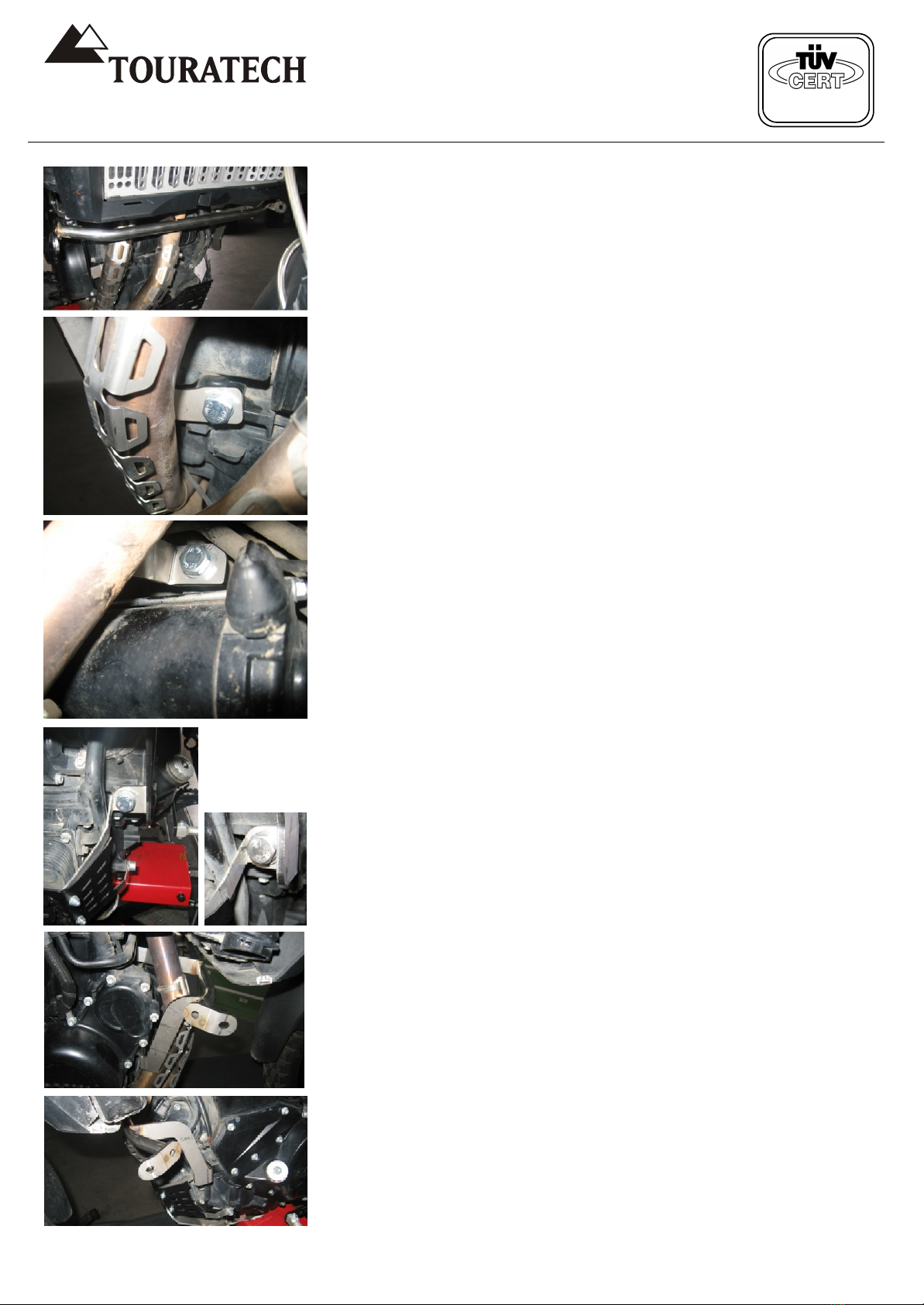
4.Verlegen Sie den Benzinschlauch auf der
rechten Seite wie auf den Bildern 4 und 5
dargestellt! Den Schlauch dabei hinter dem
Gleichrichter durchführen! Befestigen Sie 1 x
Halteblech Benzinleitung mit einer
Originalschraube am Lichtmaschinendeckel wie
in Bild4 dargestellt und sichern Sie den
Schlauch mit einem der beigelegten 290mm
Kabelbinder! Der Schlauch kann auch an der
Innenseite des Halteblechs befestigt werden!
5.Verlegen Sie den Benzinschlauch auf der
linken Seite wie auf Bild6 dargestellt!
Befestigen Sie hier ebenfalls 1 x Halteblech
Benzinleitung mit einer Originalschraube am
Kupplungsdeckel und sichern Sie den Schlauch
mit einem der beigelegten Kabelbinder 290mm!
Der Schlauch kann auch an der Innenseite des
Halteblechs befestigt werden!
6.Benzinpumpe und Steuergerät können jetzt
wieder angebaut werden! Die Verlegung der
Tankentlüftung des Hecktanks wird unter 17.
Bild29/29-1 beschrieben!
7.Kleben Sie Zellgummi-Zuschnitte der
beigelegten 10mm Matte wie in Bild7 auf die
zuvor entfetteten und gereinigten Stellen an der
Airbox und den Ansaugstutzen!
44
55
66
77
01-048-0380-0 / 01-048-0382-0 / 01-048-0384-0 / 01-048-0386-0 /
01-048-0388-0 / 01-048-0390-0
Route the fuel hose on the right side as shown
in Figures 4 and 5. Route the hose behind the
rectifier. Fasten one fuel line retaining plate on
the alternator cover using an original bolt as
shown in Fig. 4 and secure the hose with one
of the 290 mm cable ties included. The hose
can also be fastened to the inner side of the
retaining plate.
5.Route the fuel hose on the left side as shown
in Fig. 6. Here as well, fasten one fuel line
retaining plate to the clutch cover using an
original bolt and secure the hose with one of
the 290 mm cable ties included.
The hose can also be fastened to the inner side
of the retaining plate.
6. The fuel pump and control unit can now be
reinstalled. Routing the rear tank vent hose is
described under (17), Figures 29 and 29-1.
7. Affix the foam rubber pieces of the 10 mm
mat included to the degreased, clean positions
on the airbox and manifold intake as shown in
Fig. 7.
See also our catalogue
or on the Internet at www.touratech.com
Sehen Sie auch in unserem Katalog
oder im Internet unter www.touratech.com

DIN EN ISO 9001:2000
Zertifikat 15 100 42285
August 2009 August 2009
Diese Anleitung ist nach unserem derzeitigen Kenntnis-
stand verfasst. Rechtliche Ansprüche auf Richtigkeit
bestehen nicht. Technische Änderungen vorbehalten.
These instructions are at our present level of
knowledge. Legal requirements for correctness do not
exist. Technical issues subject to change.
8.Montieren Sie den Tankhalter oben rechts wie
auf den Bildern 8 und 9 (Einfädeln von unten
nach oben!) Entfernen Sie zuvor an der
Lenkerschelle die schwarze Gummierung.
Schneiden Sie von der beigelegten
Rahmenschutzfolie einen passenden Teil zu
und kleben Sie diesen wie in Bild8/9 auf den
entfetteten Rahmen. Um den Tankhalter mit der
Lenkerschelle zu befestigen, benutzen Sie eine
Linsenkopfschraube M6x20 A2 (Hinweis
beachten!). Anschließend den kleinen
Seitendeckel wieder aufstecken und den
Tankhalter zusammen mit dem Seitendeckel
wie in Bild9 mit einer
Linsenflanschkopfschraube M5x20 A2
verschrauben.
Achtung! Wichtiger Hinweis! Benutzen Sie
unbedingt ein Trennmittel (z.B. Fett oder
Kupferpaste), wenn Sie die
Linsenkopfschraube M6x20 A2 in den
Tankhalter eindrehen, damit die Schraube
nicht frisst!
9.Montieren Sie den Tankhalter oben links wie
auf den Bildern 10 und 11. Die Befestigung
erfolgt identisch wie bei Tankhalter oben rechts!
Achtung! Benutzen Sie unbedingt ein
Trennmittel (z.B. Fett oder Kupferpaste),
wenn Sie die Linsenkopfschraube M6x20 A2
in den Tankhalter eindrehen, damit die
Schraube nicht frisst!
8
9
10
11
01-048-0380-0 / 01-048-0382-0 / 01-048-0384-0 / 01-048-0386-0 /
01-048-0388-0 / 01-048-0390-0
8. Mount the tank bracket at the top right as
shown in Figures 8 and 9 (mount from the
bottom to the top!). Remove the black rubber
from the handlebar clamp beforehand. Cut a
piece to fit from the frame protection film
included and affix it to the degreased frame as
shown in Fig. 8/9. Use an M6x20 A2 oval head
bolt to attach the tank bracket with the
handlebar clamp (follow the instructions in
the note!). Then place the small side cover on
again and bolt the tank bracket together with
the side cover using an M5x20 A2 flanged oval
head bolt as shown in Fig 9.
Please note: Important note: To ensure that
the bolt does not fret, you must use a
separating agent (such as grease or copper
paste) when you fasten the M6x20 A2 oval
head bolt to the tank bracket.
9. Mount the tank bracket at the top left as
shown in Figures 10 and 11. The attachment is
made in the same manner as for the tank
bracket at the top right.
Please note: To ensure that the bolt does
not fret, you must use a separating agent
(such as grease or copper paste) when you
fasten the M6x20 A2 oval head bolt to the
tank bracket.
See also our catalogue
or on the Internet at www.touratech.com
Sehen Sie auch in unserem Katalog
oder im Internet unter www.touratech.com
DIN EN ISO 9001:2000
Zertifikat 15 100 42285
August 2009 August 2009
Diese Anleitung ist nach unserem derzeitigen Kenntnis-
stand verfasst. Rechtliche Ansprüche auf Richtigkeit
bestehen nicht. Technische Änderungen vorbehalten.
These instructions are at our present level of
knowledge. Legal requirements for correctness do not
exist. Technical issues subject to change.
10.Reinigen Sie die vorderen M10 Gewinde am
Motorblock gründlich, bevor Sie die
Querabstützung montieren. Das Gewinde muss
evtl. mit einem Gewindebohrer M10 x 1,5
nachgeschnitten werden! Die Querabstützung
von rechts nach links (in Fahrtrichtung) hinter
den Krümmern einfädeln und anschließend mit
3 x U-Scheibe M10 klein A2 und 3 x
Sechskantschraube M10x20 A2 (gefettet)
anschrauben (Bilder 12-17). Für die mittlere
Schraube (Bild14) empfehlen wir die
Verwendung eines Ringratschenschlüssels, um
das Anschrauben zu beschleunigen. Die
Schrauben noch nicht endfest anziehen, damit
die Position nach dem Aufsetzen des Tanks
korrigiert werden kann, falls erforderlich. Die
M10 Schrauben werden später mit einem
Anziehmoment von max.35 Nm angezogen!
Bild15/15.1: Wenn Sie unseren Ölfilterschutz
048-0126 montiert haben, die Blechlasche des
Ölfilterschutzes bitte AUF die Lasche der
Querabstützung schrauben, NICHT darunter!
1212
1313
1414
1515
1616
1717
15.1
01-048-0380-0 / 01-048-0382-0 / 01-048-0384-0 / 01-048-0386-0 /
01-048-0388-0 / 01-048-0390-0
10. Clean the front M10 threads on the engine
block thoroughly before installing the cross
support. They may have to be rethreaded with
an M10 x 1.5 thread tap. Mount the cross
support from right to left (in the direction of
driving) behind the manifolds and then bolt it on
with 3 x small M10 A2 washers and 3 x greased
M10x20 A2 hexagon bolts (Figures 12 through
17). For the centre bolt, (Fig. 14) we
recommend the use of a ring ratchet spanner to
facilitate the work. Do not tighten the bolts
completely yet to enable the position to be
corrected if necessary after installing the tank.
The M10 bolts are tightened later with a
maximum torque of 35 Nm.
Fig. 15/15.1: If our oil filter 048-0126 has been
installed, please bolt the sheet metal lug of the
oil filter guard ONTO the lug of the cross
support, NOT under it!
See also our catalogue
or on the Internet at www.touratech.com
Sehen Sie auch in unserem Katalog
oder im Internet unter www.touratech.com

DIN EN ISO 9001:2000
Zertifikat 15 100 42285
August 2009 August 2009
Diese Anleitung ist nach unserem derzeitigen Kenntnis-
stand verfasst. Rechtliche Ansprüche auf Richtigkeit
bestehen nicht. Technische Änderungen vorbehalten.
These instructions are at our present level of
knowledge. Legal requirements for correctness do not
exist. Technical issues subject to change.
11.Schrauben Sie die Verstellwinkel Schnabel
wie in Bild18 an die Schnabelhalter links und
rechts an mit
2 x Linsenflanschkopfschraube M5x12 A2
2 x U-Scheibe M5 groß A2
2 x Mutter selbstsichernd M5 A2
Die Schrauben noch nicht festziehen!
Alternativ können die Muttern und U-Scheiben
auch von außen und die Schrauben von innen
verschraubt werden!
Schnabelhalter links (rechts dito) wie in
Bild19/19.2 anschrauben mit 1 x
Linsenflanschkopfschraube M5x12 A2! Richten
Sie die Schnabelhalter an Kante A parallel aus.
Die Verstellwinkel bitte an Aufnahme
Windschild oder Vorbau Desierto F (B)
ausrichten und festziehen. Um den Spalt
korrekt einzuhalten die Tankblenden
provisorisch mit anbauen.
12.Die Bilder 20-23 zeigen, wie der Schnabel
zusammen mit den Tankblenden links/rechts
und der vorderen Original-Blende verschraubt
werden muss! Die originalen Blechmuttern
werden weiterverwendet!
Verwendetes Montagematerial:
2 x Distanz 4mm hoch POM schwarz (C)
2 x Distanz 3mm hoch POM schwarz (D)
(wir empfehlen diese mit Schnellkleber
anzukleben! > Bild20)
4 x Linsenflanschkopfschraube M5x20 A2
4 x Original-Blechmutter M5 > Bild21
Achtung! Die Positionen von Schnabel,
Tankblenden und Haltern müssen nach der
Montage des Tanks evtl. nochmal korrigiert
werden. Die Schrauben dann bitte erst nach
der endgültigen Festlegung der Positionen
festschrauben!
Die Tankblenden werden abschließend
zusammen mit Windschild (Vierkanteinsatz an
den seitlichen Haltern entfernen) oder Desierto
F Verkleidung und den Verstellwinkeln
Schnabel mittels
2 x Linsenflanschkopfschraube M5x20 A2
2 x U-Scheibe M5 groß A2
2 x Mutter selbstsichernd M5 A2
Verschraubt > siehe Bild19.2 (ohne Blende
dargestellt)
1818
1919
2020
2121
2222
2323
B
AA19.219.2
CCDD
FrontFront
01-048-0380-0 / 01-048-0382-0 / 01-048-0384-0 / 01-048-0386-0 /
01-048-0388-0 / 01-048-0390-0
11. Bolt the nose adjustment brackets to the left
and right nose brackets as show in Fig. 18
using:
2 x M5x12 A2 flanged oval head bolt
2 x large M5 A2 washer
2 x self-locking M5 A2 nut
Do not tighten the bolts yet!
Alternatively, the nuts and washers can also be
tightened from the outside and the bolts from
the inside.
Fasten the nose bracket left (and right) with
one M5x12 A2 flanged oval head bolt as shown
in Figs. 19 and 19.2. Align the nose bracket
parallel to Edge A. Please align the adjustment
bracket with the windscreen holder or Desierto
F (B) stem and tighten. To maintain the gap
correctly, also attach the tank shields
temporarily.
12. Figures 20 through 23 show how the nose
must be bolted together with the left & right tank
shields and the front original shield. The
original speed nuts are reused.
Fitting materials used:
2 x POM spacer, 4 mm high, black (C)
2 x POM spacer, 3 mm high, black (D)
(We recommend bonding these with instant
adhesive! > Fig. 20)
4 x M5x20 A2 flanged oval head bolt
4 x original M5 speed nut > Fig. 21
Please note: The positions of the nose, tank
shields and brackets may need to be
readjusted after installing the tank, so do
not tighten the bolts until after final
positioning.
The tank shields are then bolted together with
the windscreen (remove the rectangular insert
on the side brackets) or Desierto F fairing and
the nose adjustment brackets using
2 x M5x20 A2 flanged oval head bolt
2 x large M5 A2 washer
2 x self-locking M5 A2 nut
> See Fig. 19.2 (shown without shield)
See also our catalogue
or on the Internet at www.touratech.com
Sehen Sie auch in unserem Katalog
oder im Internet unter www.touratech.com

Diese Anleitung ist nach unserem derzeitigen Kenntnis-
stand verfasst. Rechtliche Ansprüche auf Richtigkeit
bestehen nicht. Technische Änderungen vorbehalten.
These instructions are at our present level of
knowledge. Legal requirements for correctness do not
exist. Technical issues subject to change.
DIN EN ISO 9001:2000
Zertifikat 15 100 42285
August 2009 August 2009
13.Bild 24: Stecken Sie 8 x Gummitülle von
innen und von außen in die vorderen und
hinteren Bohrungen am Tank. Damit die Tüllen
sicher gehalten werden, bitte vorne 2 x
Distanzrohr vorne 31mm und hinten 2 x
Distanzrohr hinten 37mm in bündig in die Tüllen
stecken
14.Kürzen Sie bei Benzinhahn links und rechts
bitte jeweils den Hebel bis kurz vor
Beschriftung wie in Bild25.
Achtung! Die Hebel nicht vertauschen!
Welcher Hebel für links und welcher für
rechts ist, steht auf der Verpackung!
Schrauben Sie den Filtereinsatz und das
Röhrchen heraus. Das Röhrchen entfällt.
Kürzen Sie den Filtereinsatz mit einem
scharfen Messer mittig an der ersten
Versteifungsrippe und schrauben Sie dann den
Filtereinsatz wieder in den Benzinhahn. Der
Filtereinsatz dient nach dem Kürzen lediglich
noch dazu, den O-Ring zu führen und auf
Position zu halten! Stecken Sie anschließend
den beigelegten O-Ring (aus der Verpackung
des Benzinhahns) über den Filtereinsatz.
15.Schneiden Sie vom übrigen Benzinschlauch
7,5x12,5 entsprechend der Angabe unten
Teilstücke ab und montieren Sie diese jeweils
mit dem unten aufgeführten Montagematerial.
Bild27 / Links:
1 x Benzinschlauch 7,5x12,5 > 160mm
Bild26 / Rechts:
1 x Benzinschlauch 7,5x12,5 > 100mm
Achtung! Die Längen können je nach
Verlegung etwas variieren!
Je Seite:
1 x Schnellverschluss 8mm Zapfen
2 x Schlauchklemme 11-13mm
Spiralschlauchschutz 9,5-10 nach Belieben!
Schrauben Sie anschließend die Benzinhähne
(mit montiertem O-Ring) links und rechts am
Tank fest. Benzinhahn rechts auf der rechten
Tankseite (Bild26, in Fahrtrichtung!),
Benzinhahn links auf der linken Tankseite
(Bild27)! Benutzen Sie jeweils:
2 x U-Scheibe M6 klein vz
2 x Linsenkopfschraube M6x16 vz
Achtung! Die Schrauben bitte vorsichtig
festziehen!
2424
2525
2626
2727
01-048-0380-0 / 01-048-0382-0 / 01-048-0384-0 / 01-048-0386-0 /
01-048-0388-0 / 01-048-0390-0
13. Fig. 24: Place 8 x rubber grommets in the
front and back holes on the tank from the inside
and the outside. To ensure that the grommets
are held securely, please insert the front 2 x 31
mm spacer tubes in the front and in the back,
insert 2 x 37 mm rear spacer tubes flush with
the grommets.
14. At the left and right fuel tap, please shorten
the levers to just before the lettering as shown
in Fig. 25.
Please note: Do not confuse the levers!
The packaging indicates which lever is for
the right side and which is for the left.
Unscrew the filter insert and tube. The tube is
left out. Shorten the filter insert with a sharp
knife in the middle on the first reinforcing rib
and the screw the filter insert back into the fuel
tap. After shortening, the filter insert serves only
to guide the O-ring and keep it in position. Then
place the O-ring included (from the packaging
of the fuel tap) over the filter insert.
15. From the remaining 7.5x12.5 fuel hose, cut
sections corresponding to the information
below and install each of these with the parts
listed below.
Fig. 27 / Left:
1 x fuel hose 7.5x12.5 > 160 mm
Fig 26 / Right:
1 x fuel hose 7.5x12.5 > 100 mm
Please note: The lengths can vary
somewhat depending on how the hoses are
routed.
On each side:
1 x quick coupler 8 mm, male
2 x 11-13 mm hose clamp
Spiral hose protector 9.5-10 as required.
Finally, fasten the fuel taps (with installed
O-ring) tight on the left and right of the tank.
The right fuel tap on the right side of the tank
(Fig. 26, in the driving direction!); left fuel tap on
the left side of the tank (Fig. 27). Use for each:
2 x small M6 washer, galv.
2 x M6x16 oval head bolt, galv.
Please note: Please tighten the bolts
gently!
See also our catalogue
or on the Internet at www.touratech.com
Sehen Sie auch in unserem Katalog
oder im Internet unter www.touratech.com

DIN EN ISO 9001:2000
Zertifikat 15 100 42285
August 2009 August 2009
Diese Anleitung ist nach unserem derzeitigen Kenntnis-
stand verfasst. Rechtliche Ansprüche auf Richtigkeit
bestehen nicht. Technische Änderungen vorbehalten.
These instructions are at our present level of
knowledge. Legal requirements for correctness do not
exist. Technical issues subject to change.
16.Befestigen Sie anschließend den
Überlaufstutzen M6 mit Dichtring Alu D6 an der
Unterseite des Tanks wie in Bild28 und stecken
Sie ein ausreichend langes Schlauchstück
Tankentlüftung 5x2 auf den Stutzen (ca. 70cm).
Verlegen Sie den Schlauch später nach unten!
Bild29 zeigt die Verlegung des
Überlaufschlauchs (Ü) nach unten!
17.Schneiden Sie ein ausreichend langes Stück
Tankentlüftung 5x2 (ca. 170cm) ab und stecken
Sie dieses auf den Stutzen am
Rückschlagventil des Hecktanks. Ziehen Sie
den Entlüftungsschlauch des Hecktanks wie
Original nach vorne (Bild29). Dann allerdings
wie in Bild29-1 nach oben ziehen und entlang
der Airbox und unter dieser hindurch nach
vorne verlegen. Sichern Sie anschließend den
Schlauch mit Kabelbindern 130mm.
18.Den Entlüftungsstutzen M8 mit Dichtring Alu
M8 wie in Bild30 in den Tank einschrauben und
Schlauchstück Tankentlüftung 5x2 (ca.8cm, A)
auf den Stutzen stecken. Verbinden Sie die
Entlüftung des Hecktanks B mittels des T-
Verbinders mit der Entlüftung des Fronttanks.
Stecken Sie ein Schlauchstück Tankentlüftung
5x2 (ca. 40cm, C) auf den T-Verbinder und
ziehen Sie diesen Schlauch am Vorbau entlang
nach vorne, also unterhalb der oberen
Gabelbrücke (Bild31, zeigt den Schlauch ohne
den T-Verbinder!!). Stecken Sie diesen
Schlauch auf das beigelegte Rückschlagventil
(Einbaurichtung beachten!!). Das
Rückschlagventil wie in Bild32 am Vorbau mit
Kabelbinder befestigen. Vom Rückschlagventil
aus ein weiteres Schlauchstück Tankentlüftung
5x2 nach oben als Bogen über den Vorbau
führen (Bild32-1), auf der rechten Seite wieder
nach unten zurückführen und wie in Bild33
nach hinten verlegen! Mit Kabelbindern sichern!
Prüfen Sie unbedingt mit vollem
Lenkeinschlag, nach links und nach rechts,
dass alle Schläuche frei liegen, nicht
gequetscht werden und zugentlastet sind.
29-129-1
AA
BB
CC
3030
3333
3131
3232
ÜÜ
32-132-1
2828
2929
01-048-0380-0 / 01-048-0382-0 / 01-048-0384-0 / 01-048-0386-0 /
01-048-0388-0 / 01-048-0390-0
16. Then attach the M6 overflow connection
with a D6 aluminium sealing washer to the
underside of the tank as shown in Fig. 28 and
push a sufficiently long piece of 5x2 tank vent
hose onto the connection (approx. 70 cm).
Route the hose downward later! Fig. 29 shows
how the overflow hose (Ü) is routed toward the
bottom.
17. Cut a sufficiently long piece of 5x2 tank vent
hose (approx. 170 cm) and push it onto the
connector on the check valve of the rear tank.
Pull the vent hose of the rear tank toward the
front like the original (Fig. 29). Then, however,
route it upward as in Fig. 29-1 and along the
airbox and under it toward the front. Finally,
secure the hose with 130 mm cable ties.
18. Screw in the M8 vent connection with an
M8 aluminium into the tank as
in Fig. 30 and place a piece of 5x2 tank vent
hose (approx. 8 cm, A) on the connection.
Connect the vent of the rear tank B to the front
tank vent using the T-connector. Push a piece
of 5x2 tank vent hose (approx. 40 cm, C) onto
the T-connector and pull this hose along the
stem toward the front, i.e. below the upper fork
brace (Fig. 31 shows the hose without the
T-connector). Push this hose onto the check
valve included (take care to get the
installation orientation right!) Attach the
check valve on the stem with a cable tie as
shown in Fig. 32. From the check valve, route
another piece of 5x2 tank vent hose upward in
an arc over the stem (Fig. 32-1), back
downward on the right side and toward the
back as shown in Fig. 33. Secure with cable
ties!
With the steering at full lock to the left and
right, make absolutely sure that all hoses
are unhindered, not crushed and not under
strain.
sealing washer
See also our catalogue
or on the Internet at www.touratech.com
Sehen Sie auch in unserem Katalog
oder im Internet unter www.touratech.com

19.Den Tank aufsetzen und sicherstellen, dass
alle Befestigungspunkte am Tank mit den
Haltepositionen fluchten. Evtl. müssen
Positionen der Halter etwas korrigiert werden!
Bild34: Schrauben Sie den Tank an den oberen
Tankhaltern mit je 2 x U-Scheibe M8 groß A2
und 2 x Linsenkopfschraube M8x50 A2 fest.
Benutzen Sie an den oberen Tankhaltern
unbedingt ein Trennmittel (Fett oder
Kupferpaste), um ein Festfressen der
Linsenkopfschrauben M8x50 A2 zu
verhindern.
Bild35: Schrauben Sie den Tank an der
Querabstützung jeweils wie folgt fest:
1 x U-Scheibe M8 groß A2
1 x Linsenkopfschraube M8x50 A2
1 x U-Scheibe M8 groß A2 (zwischen
Querabstützung und Gummitülle)
1 x U-Scheibe M8 klein A2
1 x Mutter selbstsichernd M8 A2
20.Bild36: Befestigen Sie die Tankblenden
abschließend links und rechts am Tank mit
jeweils
2 x U-Scheibe M6 klein A2
2 x Zylinderkopfschraube M6x12 A2
Achtung! Sofern Sie nicht schon unsere
Lenkererhöhung 048-0150 montiert haben,
bitte die beigelegte Lenkererhöhung vor
dem Anbringen der Tankblenden verbauen.
21.Nochmals alle Schlauchverbindungen und
deren Befestigungen prüfen und sicherstellen,
dass alle Schrauben festgezogen sind! Bei
Verwendung unserer LED-Blinker ist der
Abstand zum Tank zu prüfen! Falls zu eng, bitte
übrige Rahmenschutzfolie zuschneiden und an
möglichen Berührungspunkte zwischen Blinker
und Tank kleben! Zusätzlich können 3 x U-
Scheibe M5 groß A2 als Distanz hinter die
Kühlerblende geschraubt werden, um den
Abstand zu vergrößern!
Achtung! Wichtige Empfehlung zum
Fahrbetrieb! Wenn beide Tanks voll getankt
sind, die beiden Benzinhähne des
Fronttanks geschlossen lassen. Fahren Sie
den Hecktank solange leer, bis die
Tankanzeige blinkt, dann erst die beiden
Benzinhähne des Fronttanks öffnen.
DIN EN ISO 9001:2000
Zertifikat 15 100 42285
August 2009 August 2009
Diese Anleitung ist nach unserem derzeitigen Kenntnis-
stand verfasst. Rechtliche Ansprüche auf Richtigkeit
bestehen nicht. Technische Änderungen vorbehalten.
These instructions are at our present level of
knowledge. Legal requirements for correctness do not
exist. Technical issues subject to change.
3434
3535
3636
01-048-0380-0 / 01-048-0382-0 / 01-048-0384-0 / 01-048-0386-0 /
01-048-0388-0 / 01-048-0390-0
19. Put the tank in place and ensure that all
attachment points on the tank are flush with the
bracket positions. It may be necessary to
correct the positioning of the brackets
somewhat.
Fig. 34: Bolt the tank to the upper tank bracket
with 2 x large M8 A2 washers and 2 x M8x50
A2 oval head bolts in each case.
It is important to use a separating agent
(grease or copper paste) on the upper tank
brackets to prevent the M8x50 A2 oval head
bolts from fretting.
Fig. 35: Bolt the tank to the cross support as
follows in each case:
1 x large M8 A2 washer
1 x M8x50 A2 oval head bolt
1 x large M8 A2 washer (between the cross
support and rubber grommet)
1 x small M8 A2 washer
1 x self-locking M8 A2 nut
20. Fig. 36: Then attach the tank shields on the
left and right of the tank in each case with
2 x small M6 A2 washer
2 x M6x12 A2 cheese head bolt
Please note: If you do not have our
handlebar riser 048-0150 fitted already,
please install the handlebar riser included
before attaching the tank shield.
21. Check all hose connections and their
attachments once again and ensure that all
bolts are tight. If you use our LED indicators,
check the spacing from the tank! If the gap is
too small, please cut appropriate sections from
the remaining protective film for the frame and
attach it to possible points of contact between
the indicator and the tank. Also, 3 x large M5
A2 washers can be bolted behind the radiator
shield as spacers to increase the gap.
Please note: Important recommendation for
riding: if both tanks are full, leave the two
fuel taps of the front tank closed. Ride with
the rear tank until the indicator flashes to
show that it is empty, then open the two fuel
taps for the front tank.
See also our catalogue
or on the Internet at www.touratech.com
Sehen Sie auch in unserem Katalog
oder im Internet unter www.touratech.com
This manual suits for next models
5
Other Touratech Motorcycle Accessories manuals

Touratech
Touratech 01-040-2015-0 User manual

Touratech
Touratech 065-0008 User manual

Touratech
Touratech 01-040-2017-0 User manual

Touratech
Touratech 01-370-0102-0 User manual

Touratech
Touratech 01-044-0660-0 User manual

Touratech
Touratech 01-051-1200-0 User manual

Touratech
Touratech 01-048-0332-0 User manual
Popular Motorcycle Accessories manuals by other brands

Royal Enfield
Royal Enfield Himalayan Series Fitting instructions

Kabuto
Kabuto FARO instruction manual

Rekluse Motor Sports
Rekluse Motor Sports RadiusCX Clutch Installation & user guide

Urrea
Urrea USCS6 User manual and warranty

SRC
SRC Y-900GT-14-01-SL quick start guide

VM
VM VM-HF610 installation instructions


