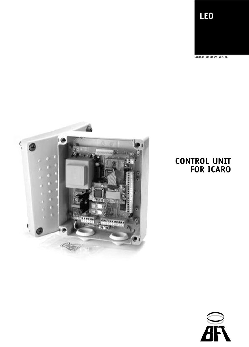
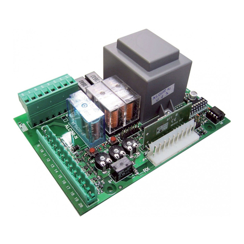
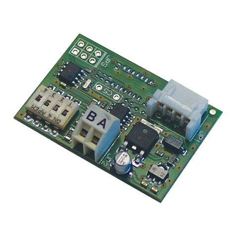
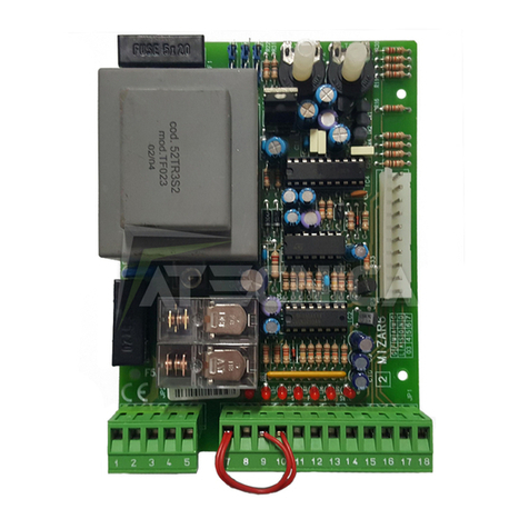
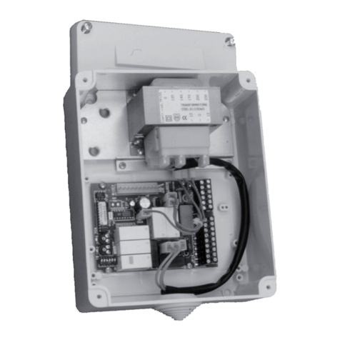
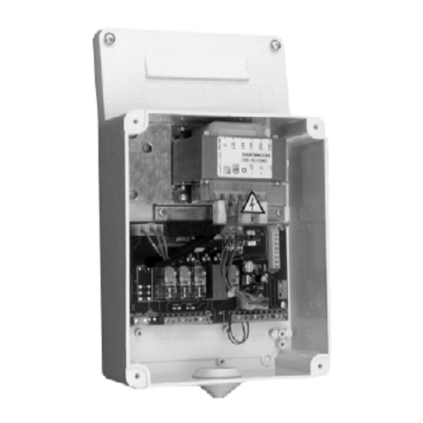
BFT PERSEO-CBE User manual

,6758=,21,'¶862(',,167$//$=,21(,167$//$7,21$1'86(5¶60$18$/,16758&7,216'¶87,/,6$7,21(7'¶,167$//$7,21,167$//$7,21681'*(%5$8&+6$1/(,781*,16758&&,21(6'(862<'(,167$/$&,213(56(2&%(3(56(2&%(
&(175$/(',&20$1'2&21752/81,7&(175$/('(&200$1'(67(8(5=(175$/(&(175$/'(0$1'2
Attenzione! Leggere attentamente le “Avvertenze” all’interno! Caution! Read “Warnings” inside carefully! Attention! Veuillez lire attentivement les Avertissements qui se trouvent à l’intérieur!
Achtun
g
!Bitte lesen Sie aufmerksam die„Hinweise“ im Inneren!
¡
Atención
¡
Leer atentamente las“Advertencias”en el interior! Let o
p
! Lees de “Waarschuwin
g
en”aan de binnenkant zor
g
vuldi
g
!
D812189 00550_01 01-02-16
CAP
MOT
B
MOT
B
COM
COM
MOT
A
MOT
A
CAP
EV1
AC2
EV2
LAMP
AC2
SEM
RED
SEM
GRN
PRESS
1
COM
PRESS
2
AN.
IN
UPS
AUX
COM
SHIELD
ANT
START
PDM
OPEN
COM
CLOSE
FTC
STOP
COM
FCA
FCC
INPUTS
INPUTS
OUTPUTS HV OUTPUTS HV
OUT4
AUX
OUT5
2ndRX
24VAC1
24VAC2
OUT LED
24VAC2
OUT BUZZER
BRK +
BRK -
OUTPUTS LV

- 2 -
Per/For
XPASS B 1200C
max 2 bollard
J4
OUT4
AUX
OUT5
2ndRX
24VAC1
CAP
MOT B
MOT B
COM
COM
MOT A
MOT A
CAP
PRES 1
COM
PRES 2
AN. IN
UPS
AUX
COM
SHIELD
ANT
24VAC2
OUT LED
24VAC2
OUT BUZZER
START
PDM
OPEN
COM
CLOSE
FTC
STOP
COM
FCA
FCC
BRK +
BRK -
OUTPUTS LV INPUTS INPUTS
J1 J3A J5A J5B
OUTPUTS HV
230V ~
50-60Hz
P
NCNCNO
NC NC
NONO NO
BZ2
BZ1
LED1 LED2
M1
BOLLARD
1
BOLLARD
2
M2
- +
EV1
AC2
EV2
LAMP
AC2
SEM RED
SEM GRN
J3B OUTPUTS HV
EV1.1 EV1.2
EV2.1 EV2.2
P
NO NO
P P
- +
+ - + -
Only with ECD
emergency ECD
(not supplied)
emergency ECD
(not supplied)
With
BATTERY
UNIT
Without
BATTERY
UNIT
NO
NO

- 3 -
Per/For
J4
OUT4
AUX
OUT5
2ndRX
24VAC1
CAP
MOT B
MOT B
COM
COM
MOT A
MOT A
CAP
PRES 1
COM
PRES 2
AN. IN
UPS
AUX
COM
SHIELD
ANT
24VAC2
OUT LED
24VAC2
OUT BUZZER
START
PDM
OPEN
COM
CLOSE
FTC
STOP
COM
FCA
FCC
BRK +
BRK -
OUTPUTS LV INPUTS INPUTS
J1 J3A J5A J5B
OUTPUTS HV
230V ~
50-60Hz
P
NCNCNO
NC NC
NONO NO
BZ2
BZ1
LED1 LED2
BZ4
BZ3
LED3 LED4
EV1
AC2
EV2
LAMP
AC2
SEM RED
SEM GRN
J3B OUTPUTS HV
EV1.1 EV1.2 EV1.3 EV1.4
P P
NC NC
P
FCC1 FCC2 FCC3 FCC4
FCA1 FCA2 FCA3 FCA4
M1
BOLLARD
1
BOLLARD
2
BOLLARD
3
BOLLARD
4
M2 M3 M4
EF1 EF2 EF3 EF4
a
c
c
b
b
NOTE / NOTES
Dissuasori elettromeccanici/Electromechanical bollards:
STOPPY MBB / STOPPY B
Dissuasori oleodinamici/Hydraulic bollards:
XPASS B 800C / PILLAR B
Solo/Only
XPASS B 800C
a
b
CAP
XPASS B 800C
PILLAR B
STOPPY MBB
STOPPY B
max 4 bollards

- 23 -
Contents
Page
1. INTRODUCTION 24
2. MAIN CHARACTERISTICS 24
3. TECHNICAL SPECIFICATIONS 25
3.1 CONTROL PANEL DIMENSIONS 25
4. INSTALLATION SAFETY 25
5. PRELIMINARY OPERATIONS 25
6. INPUT AND OUTPUT FUNCTIONALITY AND CONNECTIONS 25
6.1 J2 POWER TERMINAL BLOCK 25
6.2 J3A/J3B POWER TERMINAL BLOCK 26
6.3 J4 OUTPUTS/ACCESSORIES TERMINAL BLOCK 26
6.4 J5A/J5B INPUTS TERMINAL BLOCK 27
6.5 J6 EXPANSION CONNECTOR 27
6.6 J8 PROGRAMMER CONNECTOR
FOR RECEIVER 27
7. DISPLAY 28
7.1 STATUS CODE 28
8. PROGRAMMING 29
8.1 BASIC FUNCTIONS 29
8.2 1ST LEVEL PROGRAMMING 30
8.3 2ND LEVEL PROGRAMMING 31
8.4 3RD LEVEL PROGRAMMING 32
8.5 4TH LEVEL PROGRAMMING 33
9. RADIO RECEIVER 34
9.1 RECEIVER TECHNICAL SPECIFICATIONS 34
9.2 RADIO CHANNEL FUNCTIONALITY 34
9.3 ANTENNA INSTALLATION 34
9.4 MANUAL PROGRAMMING 34
9.5 SELF-LEARNING MODE PROGRAMMING 34
TABLE A 35
10. CONNECTIONS FOR SIMULTANEOUS OPERATION 36
11. TROUBLESHOOTING GUIDE 36
12. WARNINGS 36
13. EXAMPLES OF CONTROLLING ENTRANCES 37
13.1 INSTALLATION A CONTROLLED ENTRANCE OR EXIT 37
13.2 INSTALLATION B AUTOMATIC ENTRY OR EXIT 38
13.3 INSTALLATION C CONTROLLED ENTRY AND EXIT 39
13.4 INSTALLATION D CONTROLLED ENTRY AND AUTOMATIC EXIT 40
14. ERROR HANDLING 41

- 24 -
Control unit
EN
ENGLISH
The control unit has been developed to control automatic bollards.
= Electrical connections coming from bollard.
1. INTRODUCTION
2. MAIN CHARACTERISTICS
J1: 230Vac terminal block
J3A/J3B: Power terminal block (high voltage)
J4: Outputs/accessories power supply terminal block (low voltage)
J5A/J5B: Input terminal block
J6: Expansion connector
J8: Programmer connector for receiver
DL: 3-digit display
SW1: “START” control button
F1: Line fuse: 6.3x32 16A T
F2/F3: Low voltage fuses: 5x20 5AT
F/+/-: Programming push buttons
PR1/PR2: Radio receiver programming push buttons
- Microprocessor logic
- LEDs displaying input and output status
- Socket for integrated radio receiver 433Mhz; 2048 codes (optional)
- 3-digit display
- 2 congurable outputs
- PROGRAMMER connector for receiver
- Integrated heater
TERMON
PR2
PR1
J6
J8
F3
F2
J4
J2
F
ULINK
POWER
OUT LED
BUZZ.
OUT4
AUX
OUT5
2ndRX
BYP
EV1 EV2 LAMP SEMAPHORE
OUT4 OUT5
24VAC1
CAP
MOT
B
MOT
B
COM
COM
MOT
A
MOT
A
CAP
EV1
AC2
EV2
LAMP
AC2
SEM
RED
SEM
GRN
PRESS
1
COM
PRESS
2
AN.
IN
UPS
AUX
COM
SHIELD
ANT
24VAC2
OUT LED
24VAC2
OUT BUZZER
INPUTS
START
START
PDM
OPEN
CLOSE
FTC
STOP
FCA
FCC
UPS
AUX
PDM
OPEN
COM
CLOSE
FTC
STOP
COM
FCA
FCC
INPUTS
TRANSFORMER
BRK +
BRK -
OUTPUTS LV
F1
J1 J3A J3B
J5A
J5B
OUTPUTS HV
CAUTION!
HIGH
VOLTAGE
AREA
REPLACE
FUSES
ONLY WITH
SAME TYPE
AND RATE
230Vac
16A-T
OUTPUTS HV
START
DL
FUSE
5A-T
FUSE
5A-T
PRESS
1 2
OPEN
PRES
1 2
PDM
CLOSE
FTC
STOP
FCA
FCC
UPS
AUX
START
LED

- 25 -
Control unit
EN
ENGLISH
6. INPUT AND OUTPUT FUNCTIONALITY AND CONNECTIONS
6.1 J2 POWER TERMINAL BLOCK
3.1 CONTROL PANEL DIMENSIONS
3. TECHNICAL SPECIFICATIONS
- Power supply: 230Vac +-10%, 50/60Hz
- Motor output: 230Vac; 13A max
- Flashing light/trac light: 230Vac; 40W max
- Accessory output: 24Vac; 1A max
-Operating ambient temperature -25° +60° C
4. INSTALLATION SAFETY
In order to reach the level of safety required by current regulations, read the following prescriptions carefully.
1) Make all connections in the terminal block after carefully reading the instructions given in this manual and observing the general
rules and technical standards governing electrical systems.
2) Upstream from the installation, t an omnipole miniature circuit breaker with a contact gap of at least 3 mm.
3) If there isn’t one already, install a residual current device with a threshold of 30 mA.
4) Check the eectiveness of the grounding system and connect to it all the parts of the automation tted with a terminal or grounding
cable.
5) Fit at least one external warning device, such as a trac light or ashing light, along with a warning or danger sign.
6) Fit all the safety devices required by the type of installation, taking into consideration the risks it can cause.
7) Separate the power lines (min. sect. 1.5 mm2) from the low-voltage signal lines (min. sect. 0.5 mm2) in the ducts.
LINE 230V
230V 50/60Hz power supply with varistor internal protection and 5A T (5x20) plus 16A T (6.3x32) fuses.
Connect the phase and neutral as shown on the screen printing. Use a cable type H07RN-F 2x1.5+E min.
Connect the yellow/green wire of the power supply mains to the earth terminal of the appliance.
5. PRELIMINARY OPERATION
BOLLARD TABLE
LN E
-Operating ambient humidity up to 95%
non condensing
-Protection degree IP55
-Storage ambient temperature -25° +60° C
- Before sending a command to the automation, make sure to have selected correctly the type of bollard as follows:
Bollard selection
- Hold down buttons F and + for 5 seconds to select the connected bollard.
- Select the type of bollard using the buttons +/-.
- Press F and + to conrm.
- Select network frequency through Ht parameter. (see 3rd level programming).
- (Hydraulic bollards only) Select the pressure switch type with the parameter 33(see 3rd level programming).
- Check the connection method for simultaneous operation, if controlling multiple deterrent devices simultaneously (see paragraph 10).
*
PILLAR B 275/600
(
EASY Ø115-500 - STOPPY B 115/500
R
STOPPY Ø210-500
*
PILLAR B 275/800 - XPASS B 275/800C
(
EASY Ø200-700 - STOPPY B 200/700
R
STOPPY Ø210-700
+
PILLAR B 275/600.6C SD
)
NOT AVAILABLE
8
NOT AVAILABLE
+
PILLAR B 275/800.6C SD - XPASS B 275/800C SD
,
NOT AVAILABLE
8
NOT AVAILABLE
+
XPASS B 1200C
&$
NOT AVAILABLE
*
NOT AVAILABLE
'
STOPPY MBB 219-500.C
&%
NOT AVAILABLE
'
STOPPY MBB 219-700.C

- 26 -
Control unit
EN
ENGLISH
6.2 J3A/J3B POWER TERMINAL BLOCK
MOTA
COM
MOTB
M
CAP
CAP
EV1
AC2
EV2
AC2
SEM GRN
AC2
SEM RED
AC2
LAMP
AC2
6.3 J4 OUTPUTS/ACCESSORIES TERMINAL BLOCK
OUT5
2ndRX
24 Vac2
OUT LED
24 Vac2
24 Vac2
OUT BUZZER
BRK-
BRK+
OUT4
AUX
COM
OUT LED
COM
OUT BUZZER
MOT A - COM - MOT B
Motor connection, MOT A for open direction and MOT B for close direction
CAP
Capacitor if not present on motor(s) side
EV1
Electrovalve (230Vac RAC), for hydraulic bollards only
EV2
Electrovalve (230Vac RAC), for ECD bollards equipped only
TRAFFIC LIGHT - GREEN LAMP
Trac light outputs green lamp (230Vac)
TRAFFIC LIGHT - RED LAMP
Trac light outputs red lamp (230Vac)
FLASHING LIGHT
Flashing light, (230Vac)
EF ELECTRIC BRAKE OUTPUT (Electomechanical bollards only)
Connection for two white power supply cables for the motor’s parking electric brake.
Activation is possible only when the bollard is completely lifted (24Vcc starting / 12Vcc to stand on).
Power supply for accessories
24Vac, 1A max
Cover lights 24Vac
Self-powered output. 24Vac, 800mA max
Cover lights 12Vac (XPASS B 1200C only)
Self-powered output. 12Vac, 800mA max
Cover buzzer 24Vac
Self-powered output. 24Vac, 100mA max
Cover buzzer 12Vac (XPASS B 1200C only)
Self-powered output. 12Vac, 100mA max
OUT4/AUX
Programmable free contact relay output, max. 500mA 24 Vac/dc (parameter D8- level 2)
OUT5/2ndRX
Programmable free contact relay output/ N.O. output of the 2nd radio receiver channel; 500mA max, 24Vac/dc
(parameter D8- level 2)

- 27 -
Control unit
EN
ENGLISH
FTC
COM
STOP
COM
AUX
BRK+
PDM
COM
UPS
BRK +
PRES 2
COM
OPEN
COM
CLOSE
COM
START
COM
ANT
SHIELD
AN. IN
PRES 1
COM
6.4 J5A/J5B INPUTS TERMINAL BLOCK
FCC
COM
FCA
COM
COM
BRK+
FCC
COM
BRK +
FCA
STOP
N.C. safety input.When it is activated, the automation is immediately stopped. During the pause time, a stop control eliminates
the automatic closing, leaving the bollard open waiting for a command.
FTC
N.C. photocell input. It allows the automation to be closed only if the safety devices have not triggered. Operating mode
programmable with parameter )W-level 1.
CLOSE
N.O. closing input. It allows the automation to be closed only if the safety devices have not triggered. Operating mode pro-
grammable with parameter &/-level 1.
OPEN
N.O. opening input.
By keeping this input controlled, the automation performs the opening manoeuvre and will close automatically only when the
input is freed. Connect clocks, daily timers or weekly timers here if wanted.
START
N.O. input that operates the bollard’s opening and closing. The command is ignored while opening
PDM
Programmable Input 3G-3°liv..
May be duplicated on AUX output.
PRES 1
Closure travel limit pressure switch input (see parameter SS- level 3). Limit switch N.C. input in closing.
When activated the closing travel nishes (For hydraulic bollards only).
PRES 2
ECD pressure switch input (see parameter 3(- level 3 and parameter()- level 2).
(For ECD equipped bollards only).
UPS
UPS status input. To be connected to smart UPS with status output, active-high during mains failure. The control unit has also
an internal detector that works with simpler square-wave and quasi-sinusosidal UPS. With these simpler UPS there is no need
to use this input.
AUXILIARY INPUT AUX
For bollards with ECD device. Is active when emergency ECD command is active (see parameter SI- level 3)
ANALOG INPUT
Multi-purpose analog input 0..5V
ANTENNA
Antenna connection for the radio receiver (option).
FCC
2 wire N.O. closing limit switch imput (set parameter /7 - level 3and parameter I& - level 2).
When activated the opening travel ends (XPASS B 800C).
3 wire N.O. closing limit switch imput (set parameter /7 - level 3and parameter I& - level 2).
When activated the opening travel ends (XPASS B 1200C).
FCA
2 wire N.O. opening limit switch imput (set parameter /7 - level 3). When activated the opening travel
ends.
3 wire N.O. opening limit switch imput (set parameter /7 - level 3). When activated the opening travel
ends (XPASS B 1200C).

- 28 -
Control unit
EN
ENGLISH
.
.
6.5 J6
EXPANSION CONNECTOR
6.6 J8
PROGRAMMER CONNECTOR
FOR RECEIVER
7. DISPLAY
At power-on the display shows the board type “&G+”, then the FW release X.Y.Z, then the type of bollard (see table on chapter cap. 5),
and nally the status or error code.
The status (initial ) or error code is always displayed except in programming menu or when a blocking error is present.
The status code is shown on the rst 2 digits.
On the third digit and dot, additional information is shown:
7.1 STATUS CODE
Display STATUS
UPS active, mains voltage failure
STOP signal active
"Termon" active
Photocell engaged
A standard cycle, without errors, is always 2 -> 3 when opening, 5 -> 6 when closing
: Idle
23: Opening
: Opening limit switch reached
: Stop activated during opening
&/: Closing
: Closing limit switch reached
: Stop activated during closing
)W: Stop due to photocell triggering
: Opening after photocell triggering
: Pause after photocell triggering
2E
Hydraulic bollards only:
: Stop due to a detected obstacle
: Opening after a detected obstacle
: Pause after obstacle detection
7/: Maximum working time in opening reached
: Maximum working time in closing reached
B EBA
RS 485
LINK BBU
B EBA
TCP/IP
GATEWAY
RS485
TCP/IP
MODULE

- 29 -
Control unit
EN
ENGLISH
8. PROGRAMMING
8.1 BASIC FUNCTIONS
To access programming, press button Ffor 2 seconds.
Programming is divided into 4 levels.
To go to the next level keep button Fpressed and press the +key (Sequence 1-2-3-4-1.......).
After selecting the level wanted, press button Fto display the functions available in consecutive order. Each time F is pressed the menu shifts
to the next function (/R- &/- )W.....)
With the function selected, use the +or -key to change the value of the parameter ( +: ---... / -: ...---).
The changes made to the parameters are active immediately, but will be permanently saved only when exiting the menu, selecting the ST
function with key F.
NOTE: In case of power failure during programming, all changes will be lost.
F- +
F
F
2nd level
R6W=bollard closed
F
F
F
F
F
F
F
F
F
F
F
F F+
+
+
+
-
-
-
+
+
+
+
+
+
+
+
x 2”
x 2” x 5 x 3x 4
1st level
programming
Selects each single
1st level function
(see table par.8.2)
Selects each single
2nd level function
(see table par.8.3)
Selects each single
4th level function
(see table par.8.5)
Changes the values
of each single 1st
level function
(see table par.8.2)
Changes the values
of each single 2nd
level function
(see table par.8.3)
Changes the values
of each single 4th
level function
(see table par.8.5)
“67”function
Exit and save
programming
2nd level
programming
4th level
programming
Selecting Output2 set to closed arm:
ABC D E
Example:

- 30 -
Control unit
EN
ENGLISH
8.2 1st LEVEL PROGRAMMING
The following table gives the 1st level functions and the adjustable parameters.
= DEFAULT value set in factory. = parameter value set during installation: should be lled if
DEFAULT value is modied.
Description of level 1 parameters
·
/R: Functioning logic
- Hold-to-run: Close function active for as long as inputs are active. Open function activated by activating and releasing input. The
start command opens once and closes once.
- Semi automatic: The automation works with jog commands, without automatic reclosing. Hence, when fully open, to control closing
you need to act on the start or close command respectively.
- Automatic: The automation works in jogs. When the opening manoeuvre is completed in the standard cycle, automatic reclosing is
activated after the pause time set (parameter W3).
Par Function Settable data
/R
Selects the functioning logic.
(see notes after the table)
: Hold-to-run
: Semi automatic
: Automatic
&/
Close input conguration (see
notes after the table)
: Standard close input
: Close-when-released input
: The close command acts as a close-when-released and safety function.
)W
Photocells
: During, it reopens and waits for the photo cell free commands closing.
: When closing it reopens; closes after 1’’ when the photocell is free
: When closing it reopens; closes after 5’’ when the photocell is free
2E
Obstacle detection
(for hydraulic bollards only)
: Disabled
: When closing it stops and waits for commands
: When closing it reopens and waits for commands
: When closing it reopens, then closes after 5 seconds
S2
Opening-warning time
S&
Closing-warning time
/'
Bollard lights
: Cover lights ashing during movement, xed on when the bollard is
opened and closed
: Cover lights ashing during movement and with bollard open, xed on
when the bollard is closed
: Cover lights always ashing
: Cover lights ashing during movement and with bollard closed, xed
on when the bollard is open
W3
Pause time (in seconds) -%X
Buzzer
: Buzzer o
: Buzzer on during movement
3U
Preset controlling entrance
conguration
: none
: Conguration of installation type A parameter (see chapter 13.1)
: Conguration of installation type B parameter (see chapter 13.2)
: Conguration of installation type C parameter (see chapter 13.3)
: Conguration of installation type D parameter (see chapter 13.4)
G)
Resetting default parameters.
(see notes after the table)
: No resetting
: Resetting the default parameters
: Same as , except for “COM” parameters that are not reset
67
Exiting the menu/saving Pressing the“F” key exits the programming menu and changes are saved

- 31 -
Control unit
EN
ENGLISH
8.3 2nd LEVEL PROGRAMMING
The following table gives the 2nd level functions and the adjustable parameters.
= DEFAULT value set in factory.
·&/: Close conguration
- : Close-when-released input
The bollard closes automatically only when the vehicle has completely passed by the photocell or magnetic detector (the recom-
mended accessories for this purpose). Connect the N.O. contact of the detector or photocell to the close input terminals.
If the vehicle is on the detector or in front of the photocell it does not cause immediate closing but the control board will wait for
the signal to be released (i.e. vehicle moved).
-
: The close command acts as close-when-released and safety function.
When closing, a close command stops the automation. When close input becomes inactive the bollard resumes closing.
·3U: Preset
- To congure the parameters for installation type A, B, C and D; set the corresponding value and exit the menu. See chapter 13 for
details on installation types.
·G):Default
- To restore the parameters to the factory default values, set the “DF” to 1 or 2, then exit the menu. if 3)=the communication
“Com” settings is are kept.
Warning: The “default” operation sets all parameters to the factory default values, including the Preset values and the bollard type.
= parameter value set during installation: should be lled if DE-
FAULT value is modied.
Par Function Settable data
6U
Request for maintenance
: disabled
: active on the congured outputs
: as in plus lights ash twice
1W
Programming maintenance
cycles in thousands
1/
Programming maintenance
cycles in millions
...RR
Output 4, Output 5
: scheduled maintenance required
R R
: photocell triggering
: obstacle detection (for hydraulic bollard only)
: PDM input active
: bollard fully up (close position)
: bollard fully down (open position)
: STOP input active
: warning ash
: START input active
: OPEN input active
: power failure (the output is activated at switch-on)
: assistance required
: CLOSE input active
: UPS
: second radio channel active
: buzzer (for Totem)
)&
Closing limit switch presence
: not present see
note
: present
HI
ECD present (for SD version
and XPASS B 1200C)
: not present
: present
7H
TERMON : heating level (= min; = max)
XS
UPS
: disabled
: enabled, opens automatically during mains failure
: enabled, closes automatically during mains failure
WARNING:THIS SELECTION MAY BE DANGEROUS

- 32 -
Control unit
EN
ENGLISH
8.4 3rd LEVEL PROGRAMMING
The following table gives the 3rd level functions and the adjustable parameters.
= DEFAULT value set in factory. = parameter value set during installation: should be lled if
DEFAULT value is modied.
&U
Deceleration torque (not avail-
able for hydraulic bollards)
67
Exiting the menu/saving Pressing the“F” key exits the programming menu and changes are saved
Description of level 2 parameters
·6U: Request for maintenance
- : the request for maintenance is not active.
- : after the programmed cycles set by the counters QWand Q/, the programmed output is activated (see parameters R,R)
- : after the programmed cycles set by the counters QWand Q/, the programmed output is activated (see parameters R,R) and
the bollard lights ash twice.
·QW-Q/: Programming maintenance cycles in thousands and millions
These two parameters set the number of cycles after which a request for maintenance is signalled.
Thousands of cycles can be set with the QWparameter, millions of cycles with the Q/parameter. Example: to set maintenance alarm
after 275 000 cycles, set Q/to .and QWto .
·
)&: Closing limit switch presence.
This parameter must be set only for bollards with additional limit switch installed for closed-fully up position. After every default
operation it is set to for +and *$bollards, for the others.
·
R=;R=: Assistance required
If congured, the contact indicates that the electronic control unit detected an error in the automation and in particular, the failure
of the travel stop or the solenoid valve (hydraulic bollards only). The error is also signalled by the triple ashing of the cover lights, if
installed
· 7(: TERMON (integrated electronic motor heating system)
Should be activated ONLY when the ambient temperature where the bollard is installed drops below a minimum of 0°C for all the
day.
W(= , TERMON is disabled (default)
W(= , minimum heating
W(= , maximum heating
·
&U: Deceleration torque (electromechanical bollards only)
Sets the deceleration speed at the end of the closing manoeuvre.
The value of the deceleration speed at the end of opening is factory preset and cannot be modied.
Par. Function Settable data
3'
PDM dynamic input polarity
: input N.O.
: input N.C.
/7
Limit switch connection
: series (N.O. 2-wire sensors)
: parallel (N.C. 3-wire sensors)
33
Pressure switch polarity (for
hydraulic bollards only)
: N.O. (used until 2012)
: N.C. (used from 2013)
S(
ECD Pressure switch polarity
: N.O.
: N.C.
3$
Input AUX polarity
: N.O.
: N.C.
SS
Output 4 polarity
Output 5 polarity
: N.O.
: N.C.
&3
Commands accepted during pause
time
: OFF
: ON

- 33 -
Control unit
EN
ENGLISH
Description of level 3 parameters
·3G: Input polarity
For N.O. or N.C. input polarity conguration.
·
33: Output 4 polarity, Output 5 polarity
Output polarity: The outputs can be congured as N.O. or N.C.. NOTE: in the event of a power failure the N.C. contact opens anyway.
· 3$: Output polarity
The outputs can be congured as N.O. or N.C.. NOTE: in the event of a power failure the N.C. contact opens anyway.
·&3: Enable command during the pause time
Depending also upon other settings, the system accepts or not the commands from inputs.
·
)3: Special PDM functions
)3=PDM is used as opening enable. As long as it is not active, no opening command is accepted. Also no close command is ac-
cepted so the bollard remains open.
)3=The PDM functions as described in point 1, but in case of automatic logic, the pause time is reloaded.
)3=The PDM function enables the TERMON system. Based on the setting of the 3'parameter, the closing or opening of the
contact activates or deactivates the TERMON system. This allow the TERMON function to be controlled by a calendar and/or
a thermostat.
· 33: Pressure switch polarity
N.O.: Pressure switch type used until 2012.
N.C.: Pressure switch type used from 2013 on.
The following table gives the 4th level functions and the adjustable parameters.
= DEFAULT value set in factory. = parameter value set during installation: should be lled if
DEFAULT value is modied.
8.5 4TH LEVEL PROGRAMMING
)3
Programmable PDM input for spe-
cial functions
: None
: Opening Enable when active
: Opening Enable and pause time reset (with 3U=), when active
: TERMON Enabled when active
: Opening Enable and pause time reset (with 35=), when active
5
Radio channel 1 command selec-
tion
: Receiver channel 1 not used
: Receiver channel 1 mapped to START
: Receiver channel 1 mapped to OPEN (with SU=special function)
+W
Select mains frequency : Value of main frequency in Hertz (Hz)
67
Exiting the menu/saving Pressing the“F” key exits the programming menu and changes are saved
Par Function Settable data
&R0
Communication protocol
: disabled
: U-LINK
: Modbus/RTU
X0R
U-LINK mode
: Slave
: Master
X,G
U-LINK adress
0,G
Modbus/RTU ID
: For Slave
: For Master
063
MODBUS RTU speed
.: 19 200 baud
..38 400 baud
727
Cycles counter Read only parameter, in thousands (x1000)
(UU
Historical errors
: do not clear (keeps) the list
: clear the list

- 34 -
Control unit
EN
ENGLISH
9. RADIO RECEIVER
antenna cable RG58
9.1 RECEIVER TECHNICAL SPECIFICATIONS
- Max. n° of transmitters that can be memorized: 2048
- Frequency: 433.92MHz
- Code by means of: Rolling-code algorithm
- N° of combinations: 4 billion
9.2 RADIO CHANNELS FUNCTIONALITY
Channel 1: Select the command from parameter 5- level 2
Channel 2: Closes the relay contact on the terminal block J4: OUT4, OUT5,
if activated R=- level 2, R=- level 2 (default).
9.3 ANTENNA INSTALLATION
Use an antenna tuned to 433MHz. Con-
nect the tuned antenna to the antenna
terminals using RG58 coaxial cable.
SHIELD
ANT
J5B
Description of level 4 parameters
·&20:
Setting communication protocol.
Set value always same to Master and Slave.
·X0R:
Setting U-LINK mode.
·
X,G:
Setting U-LINK adress.
·0,G:
Setting Modbus/RTU ID.
·063:
Setting MODBUS RTU speed
·(UU:
Show the list of error codes and the number of time they occur,
alternatively.
9.4 MANUAL PROGRAMMING
In the case of standard installations where no advanced functions are required, it is possible to proceed to manual
storage of the transmitters, making reference to programming table A and to the example for basic programming.
1) If you wish the transmitter to activate output 1, press pushbutton PR1, otherwise if you wish the
transmitter to activate output 2, press pushbutton PR2.
2) When LED DL1 starts blinking, press "hidden key" on the transmitter, LED DL1 will remain continuously lit.
3) Press the key of the transmitter to be memorized, LED DL1 will ash quickly to indicate that it has been
memorized successfully. Flashing as normal will then be resumed.
4) To memorize another transmitter, repeat steps 2) and 3).
5) To exit memorizing mode, wait for the LED to go o completely or press the key of a remote control that
has just been memorized.
IMPORTANT NOTE: ATTACH THE ADHESIVE KEY LABEL TO THE FIRST MEMORISED TRANSMITTER (MASTER).
In the case of manual programming, the rst transmitter assigns the key code to the receiver; this code is necessary
in order to carry out subsequent cloning of the radio transmitters.
"Hidden key"
This mode is used to copy the keys of a transmitter already stored in the receiver memory, without accessing
the receiver.
The rst transmitter is to be memorised in manual mode (see paragraph 9.4).
a) Press hidden key on the transmitter already memorised.
b) Press key T on the transmitter already memorised, which is also to be attributed to the new transmitter.
c) Within 10 s., press "hidden key" on the new transmitter to be memorised.
d) Press key T to be attributed to the new transmitter.
e) To memorise another transmitter, repeat the procedure from step (c) within a maximum time of 10
seconds, otherwise the receiver exits the programming mode.
f ) To copy another key, repeat from step (a), having waited for the receiver to exit the programming mode
(or after disconnecting the receiver from the power supply).
9.5 SELF-LEARNING MODE PROGRAMMING
"Hidden key"
T2
T1
T3
T4

- 35 -

- 36 -
Control unit
EN
ENGLISH
11. TROUBLESHOOTING GUIDE
12. WARNINGS
The builder recommended to make an installation which has all the accessories necessary to ensure operation according to current provi-
sions, always using genuine devices.
This equipment must be installed and used in strict compliance with the manufacturer’s instructions. The manufacturer cannot be held
responsible for any damage deriving from improper or unreasonable installation and use.
The constructor disclaims all liability for any inaccuracies contained in this manual and reserves the right to make changes at any time wi-
thout any prior notice whatsoever.
10. CONNECTIONS FOR SIMULTANEOUS OPERATION (FIG. PAG. 2 and 3)
In the case of a malfunction, check that the correct bollard was selected (paragraph 5)
- Dual ashing of the cover lights. Indicates that scheduled maintenance is required. Check the parameters 6U, 1W, 1/
- Triple ashing of the cover lights and status 14 or 15 on the display at the end of the manoeuvre. Check the opening travel stop and the
pressure switch contact at the end of closing (hydraulic bollards only).
The control unit is used to operate up to a maximum of four bollards connected in parallel to thus obtain simultaneous operation with just
one control panel.
We recommend to use a junction box with adequate protection rating to complete the connections between two or more bollards. Fol-
lowing the table with indicated how to connect, serial or parallel, the common cables.
Refer to the speciÞc bollard manual for identify the right wires.
*, *, +, ++', ', (, (,), ,,
&$, &%,R, R, 8, 8
MOTOR Connect them in parallel respecting the polarity of the motors and joining the black cables, the brown cables and the blue cables
together. If present, joining the gray cables with the blue cable together.
CAPACITOR Connect in parallel the capacitor supplied with each bollard
ELECTRIC BRAKE NOT PRESENT NOT PRESENT Connect the WHITE cables of the electric
brakes in parallel
LIGHT Connect the YELLOW cables of the LED
lamps in parallel
Connect all YELLOW cables of the LED
lamps in parallel
Connect the YELLOW cables of the LED
lamps in parallel
HORN Connect the PINK cables of the horn contact in parallel
FCA Connect the GREEN cables of the limit
switch in series.
Connect the GREEN cables of the limit
switch in parallel.
Connect the GREEN cables of the limit
switch in series.
FCC Connect the PINK cables of the limit switch in series, if present
PRESSURE SWITCH
PRES1
Connect the WHITE cables of the pressure
switch in parallel (used until 2012)
Connect the WHITE wires of the pressure
switch (used from 2013) in series
Connect the VIOLET cables of the pressu-
re switch in parallel NOT PRESENT
PRESSURE SWITCH
ECD PRES2 Connect the GREEN cables of the ECD pressure switch in parallel, if present NOT PRESENT
BURGLAR Connect the ORANGE cables of the bur-
glar device contact in series, if envisaged
Connect the GREEN/BROWN cables of
the burglar device contact in parallel, if
envisaged
Connect the ORANGE cables of the bur-
glar device contact in series, if envisaged
HEATING
ELEMENT NOT PRESENT NOT PRESENT Connect the RED cables of the heating
element in parallel, if envisaged
UNLOAD ELEC-
TROVALVE EV1 Connect the RED cables of the electrovalve element in parallel NOT PRESENT
UPLOAD ELEC-
TROVALVE EV2 NOT PRESENT Connect the WHITE cables of the electro-
valve element in parallel NOT PRESENT
ECD
ELECTROVALVE NOT PRESENT Connect the PINK cables of the electro-
valve element in parallel , if ECD present NOT PRESENT

- 37 -
Control unit
EN
ENGLISH
RECOMMENDED DIMENSIONS
This solution is recommended when you want to enter a reserved area in just one direction, by activating a command (radio control, proximity
key, magnetic keys, etc.).
The vehicle approaches the
reserved area.
When the vehicle is on the loop S1
the bollard will go down only after
a command (ex.: remote control).
If the bollard is closing and the
user wants to lower it again, the
vehicle must be over loop S1 and
the command must be repeated.
When the vehicle is no longer
over loop S2 the bollard will
close.
Loops S1 and S2 also have a safety function in that they will not let the bollard to move all the time if the vehicle is over S1 or S2.
ONE DIRECTION
ONE DIRECTION
ONE DIRECTION
ONE DIRECTION
13. EXAMPLES OF CONTROLLED ENTRIES/EXITS
13.1 INSTALLATION A CONTROLLED ENTRY OR EXIT
PARAMETER DATA DESCRIPTION
35=
&/
The close command acts as a close-when-release and safety function.
5
Radio channel 1: Open
)S
Opening consent
/2
Semiautomatic logic
&3
Commands during pause is OFF
- Connect the N.O. contact of the S1 loop receiver to PDM input.
- Connect the N.O. contact of the S2 loop receiver to CLOSE input.
- The dimensional values given are approximate.
We suggest installing the “RME 2” metal mass loop detector.
*

- 38 -
Control unit
EN
ENGLISH
RECOMMENDED DIMENSIONS
This solution is recommended when you want to allow entry to a reserved area, without using any commands, allowing transit of vehicles in
just one direction.
The vehicle approaches the
reserved area. When over the
loop S1, the bollard goes down.
When the vehicle is no longer
over loop S2, the bollard will
rise again.
Loops S1 and S2 also have a safety function in that they will not let the bollard to move all the time if the vehicle is over S1 or S2.
13.2 INSTALLATION B AUTOMATIC ENTRY OR EXIT
ONE DIRECTION
ONE DIRECTION
ONE DIRECTION
PARAMETER DATA DESCRIPTION
35=
&/
The close command acts as a close-when-released and safety function.
5
Radio channel 1: Disabled
)S
Opening consent
/2
Semiautomatic logic
&3
Command during pause is OFF
- Connect the N.O. contact of the coil receiver S1 to the OPEN input.
- Connect the N.O. contact of the S2 loop receiver to the CLOSE input.
- The dimensional values given are only approximate.
We suggest installing the “RME 2” metal mass detector.
*

- 39 -
Control unit
EN
ENGLISH
This solution is recommended when you want to enter a reserved area in both directions by activating a command (radio control, proximity
key, magnetic keys, etc.).
The vehicle approaches the reserved
area.
When the vehicle is over loop S1
the bollard will go down only after a
command (ex.: remote control).
If the device is rising and the user
wants to lower it again, the vehicle
must be over loop S1 and the com-
mand must be repeated.
When the vehicle is no longer over
loop S2, the bollard will go up
automatically after an adjustable
pause time.
The vehicle approaches the reserved
area.
ENTRY
EXIT
RECOMMENDED
DIMENSIONS
When the vehicle is over loop S2,
the bollard will go down only after a
command (ex.: remote control).
If the bollard is rising and the user
wants to lower it again, the vehicle
must be over loop S2 and the com-
mand must be repeated.
Loops S1 and S2 also have a safety function in that they will not let the bollard to move all the time if the vehicle is over S1 or S2.
When the vehicle leaves
loop S1 the bollard will
rise automatically af-
ter an adjustable pause
time.
13.3 INSTALLATION C CONTROLLED ENTRY AND EXIT
PARAMETER DATA DESCRIPTION
'I=
/R
Functioning logic: Automatic
WS
Pause time
)S
Opening consent and pause time reset
5
Radio channel 1: Open
&3
Command during pause is OFF
&/
Standard close
- Connect the N.O. contact of the coil S1 and S2 receiver to
PDM input.
- The dimensional values given are approximate.
We suggest installing the “RME 2” metal mass detector.
*
Table of contents
Other BFT Control Unit manuals