manuals.online logo
Brands
  1. Home
  2. •
  3. Brands
  4. •
  5. Toyota
  6. •
  7. Car Receiver
  8. •
  9. Toyota 00016-00950 User manual

Toyota 00016-00950 User manual

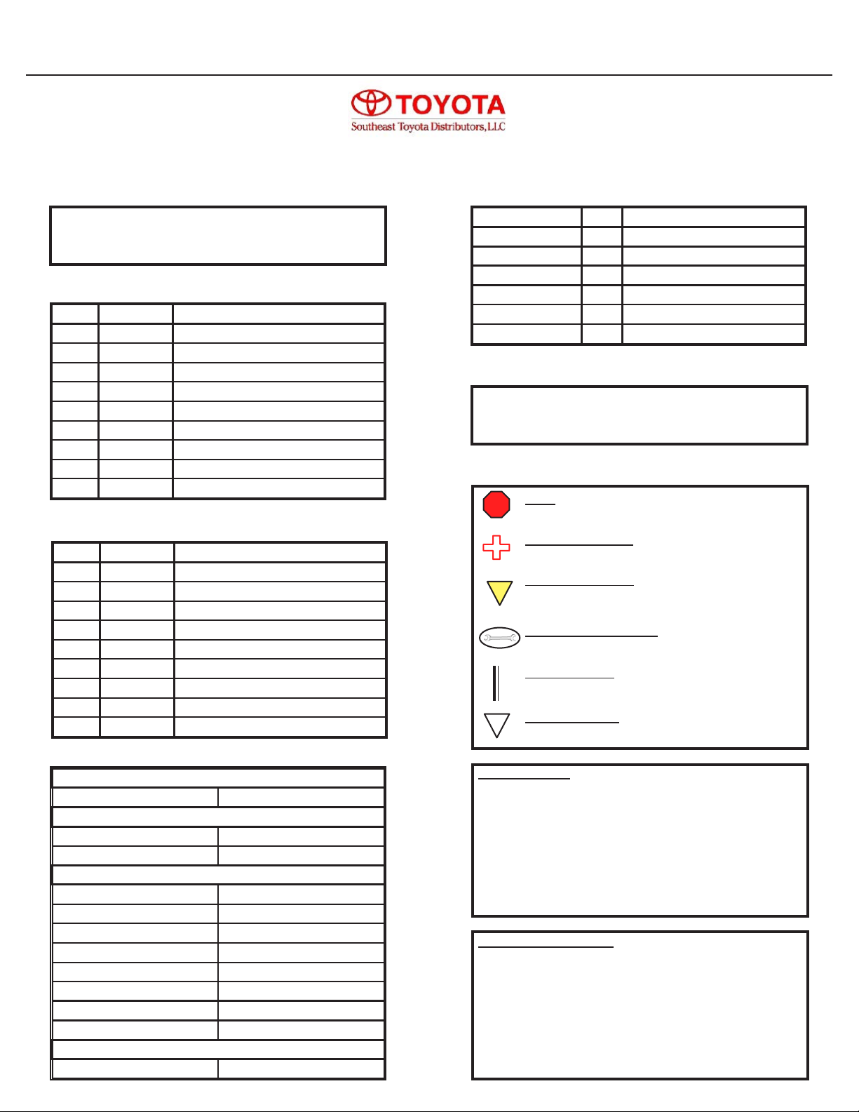
Vehicle Service Parts (May be required for reassembly)
Legend
STOP: Damage to the vehicle may occur. Do not
proceed until process has been complied with.
OPERATOR SAFETY: Use caution to avoid risk of
injury.
CRITICAL PROCESS: Proceed with caution to
ensure a quality installation. These points will be
audited on a completed vehicle installation.
TOOLS AND EQUIPMENT: This calls out the spe-
cic tools and equipment required for this process.
REVISION MARK: This mark highlights a change in
installation with respect to a previous issue.
SAFETY TORQUE: This mark indicates that torque
is related to safety.
STOP
S
SPECIAL NOTE:
After TMS and Safety mandated preparatory steps have
been taken, the installation sequence is the suggested
method for completing the accessory installation. In some
instances the suggested sequence is written for one associ-
ate to install and in others the sequence is given as part of a
team accessory installation. Unless otherwise stated in the
document, the associates may perform the installation steps
in any order to make the installation as efcient as possible
while maintaining consistent quality.
Safety Tools
Special Tools
Installation Tools
Phillips Screwdriver Straight-Slot Screwdriver
Ratchet w/ Extension 10 mm Socket
Diagonal Wire Cutters Common Pliers
Flashlight Nylon Trim Tool
Torque Wrench (48 in. lbf.) Electrical Tape
Protective Tape 1/8” Drill Bit
Power Drill
Special Chemicals
VDC Approved Cleaner
Recommended Tools
Item # Qty Reqd. Description
1 24 8” Black Cable Ties
2 2 Red T-Taps
3 2 Blue T-Taps
4 2 Black T-Taps
5 1 2” x 2” Foam Mounting Pad
6 1 3.5” x 6” Foam Pad
7 6 1 1/4” x 2 1/2” Foam Pad
8 2 1” x 1” Double Side Mounting Tape
9 4 1/2” Philips Screws
Hardware Bag Contents
Item # Qty Description
1 1 XM Module
2 1 XM Tuner Module
3 1 Wiring Harness
4 1 Hardware Bag
5 1 XM Antenna
6 2 24” Wire Ties
Kit Contents
Conicts
TOYOTA Corolla 2015 XM Satellite Radio
Part Number:00016-00950
Accessory Code: RX1000
!
1. Vehicles with factory XM radio.
2. Vehicles without touch-screen radio.
General Applicability
Rev. - 11/20/2014
1. Radios without factory XM
DIAGNOSTIC NOTE:
Diagnostic and troubleshooting information on this
accessory is available on SET Dealer Daily. Please
visit the service information section of SET Dealer
Daily for more information.
Part Number Qty Description
00016-00950-01 1 Main Wiring Harness
00016-00950-02 1 Pairing Button
00016-00950-03 1 XM Antenna
00016-00950-04 1 XM Tuner
00016-00950-05 1 Hardware Bag
00016-00950-06 1 Main Control Module
Southeast Toyota Distributors, LLC
Doc. 03.99.00 Business Partner: L95 PIO / DIO 11/21/14
Page 2 of 15
Corolla 2015 XM Satellite Radio
INSTALLATION PREPARATION
Before starting installation:
1. Familiarize yourself with the installation
instructions.
2. Inspect the kit components (Refer to Kit
Contents and Hardware Bag Contents).
Negative Battery
Cable
Left Hand Pictured
!
VEHICLE PREPARATION
1. Place protective coverings on vehicle.
2. “IMPORTANT......IMPORTANT”
Disconnect Negative Battery Cable.
3. Using a nylon trim tool, disengage the
(11) claws, (11) clips, and (1) guide and
remove the upper instrument panel trim
garnish.
4. Disengage the (6) clips and (8) claws.
Then disconnect the electrical connectors
and remove the radio trim bezel.
5. Disengage the (2) clips and (1) claw and
remove the upper instrument panel trim
panel.
Southeast Toyota Distributors, LLC
Page 3 of 15
Corolla 2015 XM Satellite Radio
VEHICLE PREPARATION; continued
6. Using a nylon trim tool, disengage the (6)
clips and (2) guides and remove the LH
instrument panel side cover.
7. Disengage the (4) clips and (2) claws and
remove the LH vent register.
8. (Optional Step) Disengage the (4) clips
and (9) claws and remove the combina-
tion meter bezel.
9. Remove the knock out cover the the hid-
den philips screw behind it. Then disen-
gage the (8) clips. Disconnect any elec-
trical connectors and remove the lower
instrument panel nish panel.
Southeast Toyota Distributors, LLC
Page 4 of 15
Corolla 2015 XM Satellite Radio
VEHICLE PREPARATION; continued
10. Remove the (4) 10 mm bolts. Disconnect
any electrical connctors and remove the
radio.
11. Disengage the (10) claws and remove the
driver’s front scuff plate.
12. Remove the plastic nut. Then disengage
the clip and remove the driver’s side kick
panel.
13. Disengage the (6) claws and remove the
driver’s rear scuff plate.
Southeast Toyota Distributors, LLC
Page 5 of 15
Corolla 2015 XM Satellite Radio
VEHICLE PREPARATION; continued
14. (Optional Step) Disengage the (2) clips
and (2) claws and loosen the driver’s rear
seat side nish panel, located just in front
of the luggage compartment. This panel
does not need to be completely removed.
15. Remove the (11) clips and remove the
luggage compartment door inside nish
cover.
16. (Optional Step) Remove the (2) screws.
Then disengage the (2) clips. Disconnect
any electrical connectors and remove the
combination meter.
17. Open the glove compartment and discon-
nect the damper. Then squeeze inward
on the sides of the glove compartment
door to disengage the (2) stoppers. Fold
the door downward to disengage the (2)
hinges and remove the glove compart-
ment door.
Southeast Toyota Distributors, LLC
Page 6 of 15
Corolla 2015 XM Satellite Radio
INSTALLATION
1. Clean antenna mounting location with
VDC approved cleaner. Then, using sup-
plied double sided tape, apply tape to the
bottom of the XM antenna. Using the
defroster grid as a reference point, center
the XM antenna along edge of trunk lid as
pictured.
2. Using supplied foam pads, place over the
XM antenna wire where shown. Route
along the path shown, and secure with
wire ties to the factory harness. Ensure
the wire is routed away from the clip
mounting location. Secure with wire ties
as necessary.
Note the lower pad must be seated along
where the weatherstrip meets the trunk
lid. This pad must be placed exactly as
shown to prevent water leaks.
3. Continue routing the XM antenna wire
along the factory wiring harness along the
REAR SIDE of the wiring harness. Se-
cure with wire ties as necessary
4. Partially pull back the trunk liner to expose
the factory wiring harness. Route the XM
antenna along the factory wiring harness
and secure with wire ties as necessary.
Centering Reference
Foam Pads Clip Mounting Location
!
Southeast Toyota Distributors, LLC
Page 7 of 15
Corolla 2015 XM Satellite Radio
INSTALLATION
5. Pull back the rear seat side nish panel
loosened previously in step 14 of disas-
sembly. Continue routing the XM antenna
along the factory wiring harness, towards
the driver’s rear door sill area, securing
the antenna to the harness with wire ties
as necessary.
6. Route the XM antenna forward along the
factory harness, towards the driver’s kick
panel.
7. Continue routing the XM antenna up the
driver’s kick panel, through the dash be-
hind the combination meter and into the
radio mounting location. Secure with wire
ties as necessary.
Southeast Toyota Distributors, LLC
Page 8 of 15
Corolla 2015 XM Satellite Radio
INSTALLATION
8. Leaving enough extra cable so that the
XM antenna will reach the module mount-
ing location, bundle any excess XM an-
tenna wire and secure to the wiring har-
ness behind the radio.
9. Apply the supplied piece of 1x1 double
sided tape to the bottom side of the pair-
ing button.
10. Attach the pairing button to the upper
right hand area, approximately 2” from the
edge above the glove compartment loca-
tion as shown.
11. Using a 1/8” drill bit, drill (2) holes for the
mounting screws. Then secure the pair-
ing button to the access panel door with
(2) supplied philips screws.
12. Route the pairing button’s wire harness
towards the module mounting location
along the top of the plastic cover. Secure
to the top of the plastic cover with (2) sup-
plied foam pads.
Module Mounting Location
2”
Pairing Button
Foam Pads
Mount button approximately 2” from edge
along the front lip of the opening.
Southeast Toyota Distributors, LLC
Page 9 of 15
Corolla 2015 XM Satellite Radio
INSTALLATION
13. Connect the main power harness, pairing
button harness, and the mini-tuner to the
interface module. Attach the XM mini-tuner
to the interface module using the supplied
2 1/4” x 2 1/4” adhesive pad.
14. Wrap the module with the supplied large
foam pad, ensuring that the connector ports
are left accessible.
15. Using the (2) 24” wire ties, secure the XM
module to the lower side of the large brace
behind the radio mounting location.
16. Route the BLACK ground wire and secure to
the ground point EB.
NOTE: Ground point EB is inside the cavity
in the white plastic harness guard along the
top of the metal brace.
17. Following the factory wiring harness, route
the RED and YELLOW wires towards the
radio harness connectors, securing with wire
ties as necessary.
18. Using a blue T-Tap, connect the RED power
wire to the LT BLUE wire of connector E1,
PIN 4.
19. Using a red T-Tap, connect the YELLOW
ACC wire to the GRAY wire of connector E1,
PIN 3.
Grount Point EB
Connector E1
Located Behind Radio
Lt. Blue
Location 4
+12VDC
(20A RADIO Fuse)
Gray
Location 3
Accessory
(7.5AACC Fuse)
Adhesive Pad
Southeast Toyota Distributors, LLC
Page 10 of 15
Corolla 2015 XM Satellite Radio
INSTALLATION
20. Reconnect the electrical connectors and
secure the radio to the dash assembly
using the (4) 10 mm bolts previously re-
moved.
21. Temporarily reconnect the negative bat-
tery cable.
Southeast Toyota Distributors, LLC
Page 11 of 15
Corolla 2015 XM Satellite Radio
PAIRING THE DEVICE:
1. Access the Bluetooth® Streaming Audio source
in the vehicle's radio.
2. Press the "Select Device" button to display the
paired device list.
3. Select the "Add" button to add the new device.
At this point the radio will enter discoverable
mode, allowing the Streaming Bluetooth®
Satellite Radio device to connect.
4. Locate the pairing button for the Bluetooth®
Satellite Radio Device in the vehicle's glove
compartment.
1. PRESS and HOLD the pairing button for
about 3 seconds. The Status Indicator
LED will start ashing RED quickly,
indicating the pairing procedure has
started.
2. Release the button when it starts to ash
RED quickly.
3. The LED will start to ash GREEN quickly,
indicating that it is connecting with the
radio.
4. Finally, the LED will begin to slowly ash
GREEN to indicate that it has successfully
paired to the vehicle's radio.
5. "SiriusXM" will now display on the paired
device list. Select the music note icon to the right
of the SiriusXM icon to select the device.
Select Device
Browse
Source
II Sound
Bluetooth Audio
System Settings Remove
Add
Bluetooth Setup
System Settings Remove
Add
SiriusXM
Bluetooth Setup
Pairing Button
Status Indicator LED
Add
Device
Select
Device
SiriusXM
Southeast Toyota Distributors, LLC
Page 12 of 15
Corolla 2015 XM Satellite Radio
VEHICLE RE-ASSEMBLY
TESTING THE RADIO
1. Prior to delivering the vehicle, test all features of the factory system according to the vehicle’s
owner’s manual.
2. Making sure that the vehicle is outside where the XM Antenna has a clear view of the sky, verify
that the radio is able to receive channel 0 (Radio ID Number) and channel 1 (Preview Channel).
You should be able to hear audio through the Preview Channel, as well as view the text data dis-
playing on the screen.
3. Check steering wheel mounted audio control functionality.
4. Place owner’s manual in the glove compartment.
1. Disconnect the negative battery terminal.
2. Refer again to the vehicle repair manual and re-assemble
all panels that were removed for installation.
2. Re-connect the negative battery cable. Torque to 48 in. lbf.
Negative Battery
Cable
Model VOL + VOL - ^ v < > Enter Back
Corolla Volume UP Volume DOWN Channel UP Channel DOWN No Function No Function No Function No Function
S
Southeast Toyota Distributors, LLC
Page 13 of 15
Corolla 2015 XM Satellite Radio
VEHICLE FUNCTION CHECKLIST
(These points must be checked to ensure a quality installation)
Headlight
If the warning lights remains on, it may indicate
a system malfunction.
High Beams
Turn Signal Lights
Tail Lights
Stop Lights
Backup Lights
Hazard Lights
Marker Lights
Dome/Courtesy Lights
Panel/Switch Illumination
Accessory Controls/Illumination
(If equipped)
Rear Window Defogger (If equipped)
Key Sensor Buzzer
Fog Lights (If equipped)
Day Time Running Lights
(If equipped)
Trunk/Tailgate/Bed Lights
(If equipped)
Glove Box Light (If equipped)
ABS Light (If equipped)
Rear Wiper/Washer (If equipped)
Clock (If equipped)
Accessory Power Socket (If equipped)
Starter
Audio/Video (If equipped)
Power Rear Door (If equipped)
Convenience Memory Settings (If equipped)
Heated Seats (If equipped)
Massage Seats (if equipped)
Power Side Mirrors (if equipped)
Side Mirror Defogger (if equipped)
Front Windshield Defogger (if equipped)
Navigation System (if equipped)
Rear Sunshade (if equipped)
Cruise Control Light (if equipped)
Steering Wheel Audio Control (if equipped)
HVAC
Power Locks (if equipped)
Power Windows (if equipped)
Gauges
Front Wiper/washer
Hood Latch Release
Passenger Air Bag Switch (if equipped)
Rollover Side Curtain Air Bag Switch (RSCA)
Horn
Seat Belt Warning Light
If the warning lights remains on, it may indicate
a system malfunction.
Air Bag Warning Light
If the warning lights remains on, it may indicate
a system malfunction.
Lamp Failure Sensor
If the warning lights remains on, it may indicate
a system malfunction.
Track/Skid Control Light (if equipped)
If the warning lights remains on, it may indicate
a system malfunction.
Tire Pressure Monitoring System (TPMS)
Prior to TPMS activation and Pre-Delivery
Service (PDS) of the vehicle the TPMS light will
blink when IG is turned on.
Southeast Toyota Distributors, LLC
Page 14 of 15
Corolla 2015 XM Satellite Radio
C-1
C-1
Block Diagram
SatStream Radio:
Kit P/N 00016-00950
C-1
Connects to
Constant +12VDC
Battery Circuit.
3
Y
B
Connects to
Chassis Ground
Location.
2
SatStream Control
Module
1
R R
Y
ACCY
GND
2 A
B+
Connects to
+12VDC Acces-
sory Circuit
Idle current draw - 4 mA
SiriusXM Tuner
Module
ANT
SiriusXM
Antenna
Pairing
Button
Shielded
Cable
Southeast Toyota Distributors, LLC
Page 15 of 15
Corolla 2015 XM Satellite Radio
Connector C-1:
Main Harness Connector
Terminal View
Checking the Harness Pinouts:
Pin Wire Color Test Reference Proper Operation
1 Red Pin 1 to Ground. Always +12 VDC.
2 Yellow Pin 2 to Ground. +12 VDC with ignition on.
0 VDC with ignition off.
3 Black Pin 3 to Ground. Always shows continuity.
4 No Connection
Unplug the 4 pin connector from the module, and perform all tests at the terminal side of the
connector. If feedback from the vehicle on any of the Pins does not match the results shown in
the Proper Operation field, then the module is not receiving the correct signals from the vehicle.
Check the connection to the vehicle wiring then re-test.
1 2
3 4
T-TAP INSTALLATION
When installing female T-Tap connectors, be sure the wire is located inside the wire channel of the female T-Tap con-
nector before closing the connector over the wire with pliers. When possible, install T-Taps at least 1" from connector.
Step A Step B Step C
Wire from
main harness
T-Tap
IMPORTANT! After installation, inspect and ensure that Keyless System Harnesses are clear of
all HOT, SHARP or MOVING objects.
IMPORTANT! Care MUST be exercised when using the BLACK T-Taps. To avoid damage and
broken wires, please note:
• Ensure there is NO tension on the T-Tap connection when securing the harness. The wire
should be slack.
• Excessive manipulation and/or stress on the wire connection could lead to wire breakage.
• Center the wire in the metal insert, NOT the plastic side of the T-Tap. Misalignment of the
wire against the metal insert could lead to cutting the wire.
• It is recommended to close close the T-Tap with your ngers (Step A above). After the
T-Tap has been closed with your ngers, applying light pressure with a set of pliers will
Southeast Toyota Distributors, LLC

Other manuals for 00016-00950

1

Other Toyota Car Receiver manuals

Toyota GENUINE AUDIO AVENSIS T25 User manual

Toyota

Toyota GENUINE AUDIO AVENSIS T25 User manual

Toyota Prius V 2014 User manual

Toyota

Toyota Prius V 2014 User manual

Toyota 2008 Camry User manual

Toyota

Toyota 2008 Camry User manual

Toyota AUDIO 1-DIN User manual

Toyota

Toyota AUDIO 1-DIN User manual

Toyota RAV4 (RHD) - MMC User manual

Toyota

Toyota RAV4 (RHD) - MMC User manual

Toyota CQ-TS7420K User manual

Toyota

Toyota CQ-TS7420K User manual

Toyota Aygo LHD User manual

Toyota

Toyota Aygo LHD User manual

Toyota CQ-VS8180A User manual

Toyota

Toyota CQ-VS8180A User manual

Toyota JBL Premium sound User manual

Toyota

Toyota JBL Premium sound User manual

Toyota Premium ICE User manual

Toyota

Toyota Premium ICE User manual

Toyota AUX-TOY3 Instruction Manual

Toyota

Toyota AUX-TOY3 Instruction Manual

Toyota CQ-ES0360A User manual

Toyota

Toyota CQ-ES0360A User manual

Toyota 4RUNNER BROCHURE 2011 User manual

Toyota

Toyota 4RUNNER BROCHURE 2011 User manual

Toyota Avensis RHD User manual

Toyota

Toyota Avensis RHD User manual

Toyota TF0411 User manual

Toyota

Toyota TF0411 User manual

Toyota RSE User manual

Toyota

Toyota RSE User manual

Toyota Prius HSD 2004 User manual

Toyota

Toyota Prius HSD 2004 User manual

Toyota CQ-VS8380A User manual

Toyota

Toyota CQ-VS8380A User manual

Toyota RAV4 (RHD) - MMC User manual

Toyota

Toyota RAV4 (RHD) - MMC User manual

Toyota CQ-LS8180A User manual

Toyota

Toyota CQ-LS8180A User manual

Toyota 08601-00911 User manual

Toyota

Toyota 08601-00911 User manual

Toyota CQ-LS7230K User manual

Toyota

Toyota CQ-LS7230K User manual

Toyota Ice User manual

Toyota

Toyota Ice User manual

Toyota Audio 2001 Avensis Verso User manual

Toyota

Toyota Audio 2001 Avensis Verso User manual

Popular Car Receiver manuals by other brands

Kenwood KDC-6024/Y Service manual

Kenwood

Kenwood KDC-6024/Y Service manual

JVC KD-PDR31 instructions

JVC

JVC KD-PDR31 instructions

Pioneer DEH-P6500R installation manual

Pioneer

Pioneer DEH-P6500R installation manual

Sony HCD-GTX888 Service manual

Sony

Sony HCD-GTX888 Service manual

Jensen BT1613 installation guide

Jensen

Jensen BT1613 installation guide

Sony CDXM60UI - Marine CD Receiver MP3/WMA/AAC... operating instructions

Sony

Sony CDXM60UI - Marine CD Receiver MP3/WMA/AAC... operating instructions

Boss Audio Systems BVS10.1B user manual

Boss Audio Systems

Boss Audio Systems BVS10.1B user manual

Roadstar RC-831RD Service manual

Roadstar

Roadstar RC-831RD Service manual

Clas Ohlson SM-8366UBR instruction manual

Clas Ohlson

Clas Ohlson SM-8366UBR instruction manual

Pioneer dex-p99rs installation manual

Pioneer

Pioneer dex-p99rs installation manual

JVC KD-G220 Service manual

JVC

JVC KD-G220 Service manual

Sencor SCT 3015MR instruction manual

Sencor

Sencor SCT 3015MR instruction manual

Pyramid CDRCS91MP Instruction & owner's manual

Pyramid

Pyramid CDRCS91MP Instruction & owner's manual

Pioneer DEH-P1Y installation manual

Pioneer

Pioneer DEH-P1Y installation manual

Blaupunkt Miami Beach CD148 Owner's records

Blaupunkt

Blaupunkt Miami Beach CD148 Owner's records

Sony CDX-RA700 - Motorized Synchro-flip Detachable... operating instructions

Sony

Sony CDX-RA700 - Motorized Synchro-flip Detachable... operating instructions

iRV iRV6500BT instruction manual

iRV

iRV iRV6500BT instruction manual

Blaupunkt St. Louis MP56 Operating and installation instructions

Blaupunkt

Blaupunkt St. Louis MP56 Operating and installation instructions

manuals.online logo
manuals.online logoBrands
  • About & Mission
  • Contact us
  • Privacy Policy
  • Terms and Conditions

Copyright 2025 Manuals.Online. All Rights Reserved.