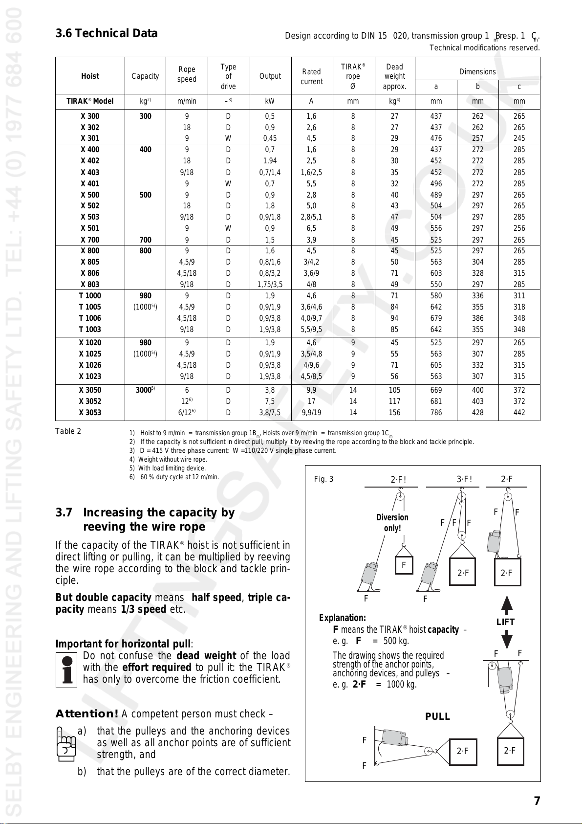
Tractel Tirak Series User manual

1
Electrically powered endless hoist
for materials handling
TIRAK®
series
T 1000
tirak®
TIRAK®
series
X 300
X 400
X 500
X 700
X 800
X 1020
TIRAK®
series
X 3050
Original Operating Instructions
This instruction manual must be available
for the user at all times.
Additional copies may be obtained on request.
With TIRAK®wire ropes
of different lengths
on winders
www.tractel.com

2
Contents
Information for this manual 2
Notes for manufacturers of installation 3
with built-in TIRAK
®
Explanation of symbols used 3
1. Safety advice 4
2. Exclusion of non intended use 5
3. Machine description
3.1 Purpose 5
3.2 Working principle 5
3.3 Allowed TIRAK
®
wire rope for
materials handling 5
3.4 Noise emission 5
3.5 Main components and
operating controls 6
3.6 Technical data 7
3.7 Increasing the capacity 7
3.8 Anchoring examples 8
3.9 Safety devices
3.9.1 Primary brake 8
3.9.2 Emergency stop 8
3.9.3 Phase control relay 8
3.9.4. Load limiting device 8/9
3.9.5 Manual operation
3.9.5.1 Emergency descent 9
3.9.5.2 Manual lifting 9
3.10 Residual risks 10
4. Setting up
4.1 Required equipment 10
4.2 Anchoring the TIRAK
®
hoist
4.2.1 Anchoring devices and
dimensions 10/11
4.2.2 Anchoring of the TIRAK
®
hoist 12/13
4.3 Wire rope exit
4.3.1 Slack wire rope 13
4.3.2 Use of wire rope winders 13
4.4 Electric connections 14
4.5 Electric controls 15
Page
4.6 Wire rope installation
4.6.1 Preparing the wire ropes 15
4.6.2 Wire rope installation 16
5. Operation
5.1 Checks before starting 17
5.2 Weekly check of wire rope and cable 17
5.3 Operation
5.3.1 Stop/EMERGENCY STOP 17
5.3.2 Service operation 17
5.4 Securing moving loads 18
5.5 Manual operation
5.5.1 Emergency descent 18
5.5.2 Manual lifting 18
6. Troubleshooting 18/19/20
7. Out of Operation
7.1 Temporary stoppage 20
7.2 End of operation 20
8. Maintenance/Checks/Repair
8.1 Maintenance
8.1.1 Hoist 21
8.1.2 Wire ropes 21
8.1.3 Motor, brake, and gear box 21
8.2 Checks
8.2.1 Essential checks 22
8.2.2 Safety inspection 23
8.3 Repair 23
9. Spare Parts 23
9.1 Hoist 23
9.2 Motor and brake 23
9.3 Electrical control 23
9.4 Nameplates and labels 23
Page
Date of edition
2nd Edition: February 2004
Copyright
The copyright of these assembly and operating
instructions shall remain with the manufacturer.
Address of the manufacturer:
GREIFZUG Hebezeugbau GmbH
Scheidtbachstraße 19-21
51469 Bergisch Gladbach
Germany
Phone: +49 / 22 02 / 10 04-0
Fax: +49 / 22 02 / 10 04-50 or -70
For addresses of other TRACTEL Group Companies see page 28.

3
Notes for manufacturers of an installation with built-in TIRAK®
Important!
The manufacturer of an installation for lifting/
pulling/driving loads in which a TIRAK
®
hoist is
built in must indicate all instructions for the safe
use of this installation at the corresponding points
of the instructions which must be prepared for
the installation by the manufacturer.
STOP
Merely enclosing these instructions does not
satisfy the requirements of the EC Machinery
Directive or the applicable standards!
(without code word)
Explanation of symbols used
Safety advices
Symbol Code word Meaning Possible consequences of non-compliance
IMMEDIATE or
DANGER possibly imminent Fatal or serious injuries!
danger:
IMMEDIATE or
DANGER possibly imminent
danger through Fatal or serious injuries!
dangerous
voltage:
Possibly
CAUTION dangerous Injuries to persons
situation: or damage to property.
Other advices
Possibly
Attention dangerous Damage to appliance.
situation: or its surroundings.
Important Useful tips for
optimum working: None
Directions
Instruction to operation/
documentation in writing.

4
Follow all instructions and safety regu-
lations contained in this
manual to avoid injuries.
a) DO NOT overload the TIRAK
®
hoist.
b) DO NOT stand below a suspended load.
c) TIRAK
®
hoists must only be used for lifting, pull-
ing, lowering, and moving back-and-fro of loads
1)
.
Use for other purposes is not allowed.
d) TIRAK
®
hoists with standard electric equipment
must not be used in a potentially explosive at-
mosphere
2)
.
e) Anchoring, maintenance, and/or the operation of
TIRAK
®
hoists must only be done by persons,
who are familiar with it. Employees must have
received the instruction to anchor, maintain, and/
or operate the hoist by their employer.
f) The operator has to know and to follow all rel-
evant local safety regulations, and maintenance
recommendations, as well as this operating in-
struction, and the operator must have been
instructed.
g) The operator must not start any movement of the
load until he has checked that the hoist and the
load are properly anchored, and that no person is
stood in the danger zone below any suspended
load, or until he has got a starting signal from the
slinger.
h) The operator must watch the load during all move-
ment operations of the hoist. If the operator is
unable to watch the complete working area, the
danger zone must be cordoned off, or a second
person must be positioned to enable the com-
plete working area to be watched and have
adequate means of communication with the hoist
operator during the whole operation.
i) The TIRAK
®
hoist has to be anchored so that the
wire rope under load is vertically entering the
hoist.
k) Use only the recommended TIRAK
®
rope in good
condition. Use only normally commercially avail-
able multi-purpose grease for the lubrication of
the rope. Do not use lubricants containing disul-
phide (e.g. Molycote
®
).
l) When using a rope other than the recommended
TIRAK
®
rope the warranty entitlement given by
GREIFZUG Hebezeugbau GmbH or other com-
pany of the TRACTEL Group shall not apply.
1) TIRAK
®
-Hoists for man riding on request.
2) TIRAK
®
-Hoists can be supplied for these applications on request.
1. Safety advice
m) Before starting the assembly check all parts for
completeness and error-free quality.
n) Only anchor the TIRAK
®
hoist at the points pro-
vided for this purpose (connection rods, anchor
points, or load pins).
o) When using self-securing nuts please observe
the following:
–the screw must protrude from the nut with at
least half its thread diameter;
–do not re-use nuts if they can be unscrewed
by hand!
p) Do not use the wire rope to fix the load, and do
not pull it over sharp edges.
q) Do not fix any load to the free wire rope end,
which exits from the winch at the opposite side to
the wire rope under load.
Exception: Use of a TIRAK
®
hoist of the type
series T 1000 in to-and-fro travel.
r) Never use a rope which is too short for the job
you are doing. When the load or machine is at its
lowest point, a minimum length of 1meter of wire
rope should be below the rope exit of the TIRAK
®
.
s) The ferrule of the wire rope hook must not reach
the TIRAK
®
-casing during lifting/pulling the load.
Exception: A limit switch for lifting limitation is
attached to the TIRAK
®
hoist (see accessories on
page 25).
t) The electrical connection of the TIRAK
®
as well
as of electrical accessories must be carried out
in accordance with EN 60204-1.
u) Checks and repairs to the electrical system must
only be carried out by qualified electricians.
v) Other checks and repairs must only be carried
out by GREIFZUG Hebezeugbau GmbH, an other
company of the TRACTEL Group or by a hoist
workshop.
w) GREIFZUG Hebezeugbau GmbH or other com-
pany of the TRACTEL Group shall assume no
liability for damages resulting from conversions
or alterations to the devices supplied by itself or
as a result of the use of non-original parts.

5
2. Exclusion of non-intended use
3. Machine description
3.1 Purpose
TIRAK
®
hoists of the series
X 300 , X 400 / X 500 , X 700 , X 800,
T 1020, X 1000, X 3050
are portable, electric driven hoists for
lifting, lowering, pulling, and
movement of loads
by means of a TIRAK
®
wire rope prescribed by the
manufacturer.
This wire rope is mandatory for the safe and trouble-
free working with TIRAK
®
hoists.
DIN
G
B
8
Fig. 1
3.3 Allowed TIRAK®wire rope for
materials handling
for TIRAK
®
-series Wire rope-Ø
X 300 8 mm
X 400
X 500
X 700
X 800
T 1000
X 1020 9 mm
X 3050 14 mm
Identification: one red strand.
Diamater indication on the ferrule:
3.4 Noise emission
TIRAK
®
series (Distance 1 m)
X 300/400:............................................................................max. 72 dB(A)
X 500/700/800/1020, T 1000:....................max. 70 dB(A)
X 3050................................................................................. max. 78,5 dB(A)
3.2 Working principle
Provided that TIRAK
®
hoists are aligned in the direc-
tion of pull, they will work in any position and in any
direction.
For either lifting or lowering there is one correspond-
ing push button. The wire rope is driven through the
winch with constantly equal safety, and the length of
wire rope i. e. the possible pulling length, is practi-
cally unlimited.
TIRAK
®
hoists with a capacity of 1000 kg or more
have an integrated load limiting device.
TIRAK
®
hoists of T 1000 series can pull in both
directions.
Indication
on the ferrulle:
example for
8 mm dia.
Use of standard TIRAK
®
hoists and other equipment for materials handling
under the following conditions is prohibited:
–at temperatures below -10
Cor above +50
C,
for X 1030 to 2050 P series below -15
Cor above +80
C
(for advice regarding gearbox oils for lower/higher temperatures
see chapter 8.3);
–in potentially explosive atmosphere.
Machines for these conditions can be supplied on request.
Table 1

6
5
5
3.5 Main components and operating controls
TIRAK®
series
T 1000
7
2
6
4a
3
1
ab
c
b
c
a
1. Wire rope drive mechanism
2. Motor
3. Gearbox
4. Controls
awith central control box
bat the terminal box
cwith pendant control, mounted on the terminal
box
dwith pendant control, with connector
5. Where appliable:
connector to the central control box
6. Brake release lever
7. Wire rope
TIRAK®
series
X 300
X 400
X 500
X 700
X 800
X 1020
3
2
1
7
4b
7
4c
Fig. 2a
TIRAK®
series
X 3050
b
c
a
3
2
1
7
Fig. 2b
Fig. 2c
Fig. 2d
8
6
5

7
Rope Type TIRAK
®
Dead
Rated Dimensions
Hoist Capacity speed of Output rope weight
current
drive Ø approx. a b c
TIRAK
®
Model kg
2)
m/min –
3)
kW A mm kg
4)
mm mm mm
X 300 300 9D0,5 1,6 8 27 437 262 265
X 302 18 D 0,9 2,6 8 27 437 262 265
X 301 9W0,45 4,5 8 29 476 257 245
X 400 400 9D0,7 1,6 8 29 437 272 285
X 402 18 D 1,94 2,5 8 30 452 272 285
X 403 9/18 D 0,7/1,4 1,6/2,5 8 35 452 272 285
X 401 9W0,7 5,5 8 32 496 272 285
X 500 500 9D0,9 2,8 8 40 489 297 265
X 502 18 D 1,8 5,0 8 43 504 297 265
X 503 9/18 D 0,9/1,8 2,8/5,1 8 47 504 297 285
X 501 9W0,9 6,5 8 49 556 297 256
X 700 700 9D1,5 3,9 8 45 525 297 265
X 800 800 9D1,6 4,5 8 45 525 297 265
X 805 4,5/9 D 0,8/1,6 3/4,2 8 50 563 304 285
X 806 4,5/18 D 0,8/3,2 3,6/9 8 71 603 328 315
X 803 9/18 D 1,75/3,5 4/8 8 49 550 297 285
T 1000 980 9D1,9 4,6 8 71 580 336 311
T 1005 (1000
5)
)4,5/9 D 0,9/1,9 3,6/4,6 8 84 642 355 318
T 1006 4,5/18 D 0,9/3,8 4,0/9,7 8 94 679 386 348
T 1003 9/18 D 1,9/3,8 5,5/9,5 8 85 642 355 348
X 1020 980 9D1,9 4,6 9 45 525 297 265
X 1025 (1000
5)
)4,5/9 D 0,9/1,9 3,5/4,8 9 55 563 307 285
X 1026 4,5/18 D 0,9/3,8 4/9,6 9 71 605 332 315
X 1023 9/18 D 1,9/3,8 4,5/8,5 9 56 563 307 315
X 3050 3000
5)
6D3,8 9,9 14 105 669 400 372
X 3052 12
6)
D7,5 17 14 117 681 403 372
X 3053 6/12
6)
D3,8/7,5 9,9/19 14 156 786 428 442
3.6 Technical Data
Table 2
1) Hoist to 9 m/min = transmission group 1B
m
, Hoists over 9 m/min = transmission group 1C
m
2) If the capacity is not sufficient in direct pull, multiply it by reeving the rope according to the block and tackle principle.
3)
D = 415 V three phase current; W =110/220 V single phase current.
4) Weight without wire rope.
5) With load limiting device.
6) 60 % duty cycle at 12 m/min.
Design according to DIN 15020, transmission group 1B
m
resp. 1C
m
.
Technical modifications reserved.
Fig. 3 2·F
3·F!
2·F!
F
F
F
F2·F 2·F
Diversion
only!
F
F
F
F
F
F
2·F
LIFT
F
F
2·F
PULL
Explanation:
F
means the TIRAK
®
hoist capacity –
e. g.
F
= 500 kg.
The drawing shows the required
strength of the anchor points,
anchoring devices, and pulleys –
e. g.
2·F
= 1000 kg.
3.7 Increasing the capacity by
reeving the wire rope
If the capacity of the TIRAK
®
hoist is not sufficient in
direct lifting or pulling, it can be multiplied by reeving
the wire rope according to the block and tackle prin-
ciple.
But double capacity means half speed, triple ca-
pacity means 1/3 speed etc.
Important for horizontal pull:
Do not confuse the dead weight of the load
with the effort required to pull it: the TIRAK
®
has only to overcome the friction coefficient.
Attention!
A competent person must check –
a) that the pulleys and the anchoring devices
as well as all anchor points are of sufficient
strength, and
b) that the pulleys are of the correct diameter.

8
3.8 Anchoring examples for materials handling
Fig. 4b
Fig. 4a
Pulling
Fig. 4c Fig. 4d
To-and-fro-Driving
Only TIRAK
®
T 1000
series
Fig. 4f
Fig. 4e
Lifting
Prevent the
load from
rotating!
3.9 Safety devices
3.9.1 Primary brake
Electromagnetic brake which closes automatically
–if the UP/Down-button is released
–in case of power supply failure.
3.9.2 Emergency Stop
Pushing the red EMERGENCY STOP button in case
of emergency completely switches off the hoist con-
trol. To start after clearing the problem, turn the
EMERGENCY-STOP button clockwise until it re-
leases.
3.9.3 Phase control relay
In controls with 3-phase motors, the integrated phase
control relay stops the operation if the phases are
reversed. This prevents wrong coordination of the
UP/DOWN-buttons which would prevent operation of
the load limiting device.
Correction: turn the phase inverter of the plug by
180(Fig. 6).
UP
DOWN
EMERGENCY
STOP
Fig. 5
Fig. 6
3.9.4 Load limiting device
TIRAK
®
-Models with 1000 kg capacity or more are
equipped with a load limiting device.
The load limiting device is set by the manufacturer in
such a manner that it switches off the lifting move-
ment at the latest when the load has reached 1.25
times the carrying capacity of the hoist.
3.9.4.1 Electronic pulling force limiting device
Possible causes for switching off:
–overload or
–blocking of the load when lifting/pulling.
Phase inverter
in CE-plug

9
Action following switching off:
Press DOWN button,
–until the load has settled and reduce the load
until there is no longer any overload or
–until the load is free from the obstacle. Remove
the obstacle before continuing to lift or pull.
Function of the load limiting device
The electronic load limiting device reacts to the cur-
rent consumption of the motor. The overload is
detected during lifting/pulling.
Reducing the switch off threshold value
Setting to a lower threshold value e.g. as a result of a
lower carrying capacity of the components to which
the hoist or diverter pulleys are anchored, can only be
carried out by a qualified electrician or a hoist work-
shop (fig. 7):
A Pre-Setting
A.1 Nominal curent
Turn upper regulator to the right as far as the
stop.
A.2 Start-bridging
Turn lower regulator to the right as far as the
stop.
B. Setting
(Example for TIRAK
®
X 1030)
B.1 Setting the overload
Attach overload = rated load + 25 %
(e. g. 1250 kg)
During the lifting of the overload turn the upper
regulator to the left until the hoist stops.
Lower overload until the rope is slack.
Again lift overload – the hoist must stop as soon
as it comes under load.
Press UP button – the hoist must stop immedi-
ately.
Following each stopping of the hoist during
this setting procedure, press the DOWN button
shortly so that the upward travel is again possi-
ble.
Step by step
–turn the lower regulator slightly to the right,
–then press UP button,
until lifting of the suspended nominal load is
possible.
Important note for TIRAK
®
with 2 speeds
(pole changing motor):
The control system contains 2 load limiting
devices, the setting must be carried out for
both speeds.
3.9.4.2 Mechanical load limiting device
The load limiting device is installed in the rope drive
and switches off the UPWARD travel in the event of
overload.
Possible causes of switching off:
–overload or
–blocking of the load when lifting/pulling.
Action following switching off:
Press DOWN button,
–until the load has settled and reduce the load
until there is no longer any overload or
–until the load is free from the obstacle; remove
obstacle before continuing to lift or pull.
Fig. 7
START
Hysterese (= I
S
x 0,5)
U
Y1 Y2
I
S
R
5A 250V~ 1000VA
A1 A2 K I1 I2 Y1 Y2 12 11 14
~
5 A
10 A
I
N
= 5 A, 10 A ~
GREIFZUG
U
I
N
Speicher
R
START
0
0,5 s
TIH4X-G
A1 11 K I1 I2
(N) (L) (L)
10A 5A
U
12 14 Y1 Y2 A2
12 14
11
10 % 100
40 60
80
Electronic load limiting device
B.2 Setting the rated load
Attach rated load (e. g. 1000 kg) and lift the
nominal load from ground.
Turn lower regulator to the left as far as the
stop.
3.9.5 Manual operation
Details in chapter 5.5 on page 18
3.9.5.1 Emergency Descent
In case of power failure you can manually open
the brake with lever (1) (Fig. 8).
3.9.5.2 Manual lifting
With the brake opened the load can be lifted
with the hand wheel (2) placed on the motor shaft
(Fig.8).
2
1
Fig. 8

10
TIRAK
®
series
X 300/400 X 500 / 700 / 800 T 1000 X 3050
X 1020
Dimensions [mm]
a255 300 449 570
b220 267 250 360
c60 60 56 117
Ø d 10,5 10,5 - 16,1
e- 35 - 45
e
1
---35
f- 67 - 132
g- 26 28 40
h- 19 14 27
h
1
---70
Ø i - 16,5 16,5 30,1
k112 100 - -
l40 40 - 70
m12 12 - -
n98 98 - -
o32 32 - -
p26 26 - -
Ø q 13 13 - -
4. Setting up
4.1 Required equipment
a) TIRAK
®
of correct capacity, speed and voltage.
Machines with a capacity of 1000 kg or more
must have a built-in load limiting device.
b) TIRAK
®
wire rope with correct diameter and of
sufficient length. Grease to lubricate the rope
c) Electric supply cable of correct type and required
length, with correct number of wires and cross
sectional area.
d) Anchoring devices for fixing the load i.e. slings,
belts or similar of sufficient strength.
e) Pulleys for diverting or reeving the wire rope of
sufficient strength and diameter.
Check condition of all components.
3.10 Residual risks
CAUTION!
The following risks are not constructively
covered for the TIRAK
®
hoist :
On TIRAK
®
hoists without limit switch (standard
version):
a) Damage to the rope when the rope hook is
pulled as far as the TIRAK
®
housing. Conse-
quently observe rope hook during lifting/
pulling so as to be able to stop in time.
b) Running out of the slack wire rope end. Conse-
quently
–always ensure a sufficiently long rope;
–watch rope end during lowering/slacken-
ing so as to be able to stop in good time.
On TIRAK
®
hoists with load limiting device:
c) The load limiting device is set to the maximum
carrying capacity of the respective hoist. Should
a lower value be necessary e.g. due to a lower
carrying capacity of components to which the
hoist or diverter pulleys are anchored:
–have electronic load limiting device set by
a qualified person (see section 3.9.4);
–have mechanical load limiting device set by
the manufacturer.
d) The electronic load limiting device only de-
tects an overload during lifting/pulling. Therefore
particular care should be exercised when a load
carrying device (material container or similar) is
loaded when suspended or being lowered.
4.2 Anchoring the TIRAK®-Hoist
4.2.1 Anchoring devices and
dimensions
Table 3
Fig. 9
bc
a
Ø d
A
Series X 300/400
Dimension

11
h
g
h1
c
b
Ø i
f
e
e1
Ø d
a
l
AB
Series T 1000
h
g
c
b
a
Ø i
C
D
Ø i
Fig. 12
h
g
c
b
a
Ø d
Ø i f
e
A
B
Fig. 10
k
pl
on
m
Ø q
Fig. 11
Adapter (optional) for
Series X 300/400/500/700/800/1020
Series
X 500/700/800/1020
Series X 3050
Fig. 13
Anchoring devices
–Series X 300/400/500/700/800 and
X 1020 when screwing the housing
to the points (A):
M10x… screws, at least grade 8.8
with self-locking nuts;
–series X 300/400/500/700/800 and
X 1020 when anchoring by means
of the adapter (Fig. 11):
M12x…screws, at least grade 8.8
with self-locking nuts;
–Series X 500/700/800/1020 P when
screwing the housing to point (B):
M16x… screws, at least grade 8.8
with self-locking nuts;
–Series T 1000 at points (C + D):
M16x… screws, at least grade 8.8
with self-locking nuts;
–Series X 3050 when screwing the
housing to the points (A):
M16x… screws, at least grade 8.8
with self-locking nuts;
–Series X 3050 when screwing to
point (B):
M30x… screws, at least grade 8.8
with self-locking nuts;
Instead of the screws, bolts or similar
with at least the same strength can
be used.

12
90
Wire rope
under load
slack
wire rope
Fig. 14
B
Adapter
Fig. 15
Series X 300/500/700/800/1020
series X 3050
A1A2
A4A3
4.2.2 Anchoring the TIRAK®hoist
Attention:
ALWAYS anchor the TIRAK
®
hoist in such
way that the wire rope enters the hoist per-
pendicularly, when under load (Fig. 14)
A) TIRAK®-series
X 300 / 400 / 500 / 700 / 800 / 1020
(Fig. 14)
–Anchor TIRAK
®
with the adapter at point (B),
or
–anchor the TIRAK
®
hoist at least at two of
the four anchoring points (A);
allowed: A
1
<–>A
2
,
A
2
<–>A
3
,
A
3
<–>A
4
Attention!
NOT allowed: anchoring only
at points A
1
<–>A
3
or A
1
<–>A
4
or A
2
<–>A
4
.
B) TIRAK®-series X 3050
(Fig. 15)
–Anchor TIRAK
®
hoist with bolt or shackle at
point (B).
Attention:
Support TIRAK
®
-hoist with additional adapters
in the direction of pull.
–Or anchor the TIRAK
®
hoist at least at two of
the four anchoring points (A
1
to A
4
);
allowed: A
1
<–>A
2
, A
2
<–>A
3
,
A
3
<–>A
4
,
Attention!
NOT allowed: anchoring only
at points A
1
<–>A
3
or A
1
<–>A
4
or A
2
<–>A
4
.
Attention:
It must be ensured by means of the mounting
(C) that the force is distributed evenly over
both anchor points.
Important:
When planning the anchoring we recommend
consultation with the manufacturer.
90
wire rope under load
slack
wire rope
B
A1
C
Mounting
for lateral
anchoring
A2
A4A3
flat steel 60 x 12,
165 long
Square tube
120 x 4.5, DIN 59410

13
90
Fig. 19
Slack
wire rope
pulley
Fig. 16
C
A1
A2
B1
B2
Fig. 18
Safety pin
D) All TIRAK®hoists!
Attention
:
When using an anchor bolt with safety pin:
Check the correct position of the safety pin
according to Fig. 18.
4.3 Wire rope exit
4.3.1 Slack wire rope
Always ensure that the wire rope exit is not obstructed!
Use a diverter pulley for the slack wire rope (Fig. 19)
to prevent damage or use another wire rope leading
system to prevent damage from rubbing over sharp
edges.
Make sure that the slack wire rope
–is freely hanging down and able to untwist itself
or
–is properly reeled to prevent the formation of
loops/knots (Fig. 20)
4.3.2 Use of wire rope winders
The loose, unloaded end ot the wire rope can also
be stored on suitable wire rope winders (e.g. motor
or spring wire rope drums).
When planning we recommend consulting the manu-
facturer of the TIRAK
®
hoists regarding design and
arrangement of the wire rope winders.
Slack wire rope
Fig. 20
C) TIRAK®series T 1000
(Fig. 16)
–If the load is to be pulled by the hook (C) in
the direction of wire rope entry (A1), the
TIRAK
®
must be anchored at point (B1).
Attention
:
On the screw connection (a) only
tighten the securing nut to such an extent that
approx. 1 mm play remains to the anchoring
links (b) since otherwise these could be dam-
aged (fig. 17).
Attention
:
If the load is to be pulled in the
direction of wire rope entry (A2), the TIRAK
®
must be anchored at the point (B2) and the
control must be changed by a qualified elec-
trician so that the correct connection for UP-/
DOWN-buttons is guaranteed.
–When pulling in both directions, you must
anchor the TIRAK
®
at both points (B1 and
B2). (Fig. 16).
A tip: Mobile hoists with the TIRAK
®
are a
very compact unit of hoist and wire rope
winder. Details on page 26.
Fig. 17
Anchoring device
a
b

14
4.4 Electrical Connections
DANGER!
The electrical connection for TIRAK® hoists
must conform to EN 60204-1.
The lead must be protected by fuse by the
customer.
Always pull the plug out before opening a
central control!
a) Ensure that the mains voltage is adequate for
the motor of the TIRAK
®
–
–Three phase:
400 V (3P + E + 0), 50 Hz,
16 amp rated plug and socket
–Single phase:
230 V (2P + E), 50 Hz,
16 amp rated plug and socket
If in doubt ask
.
b) To avoid power loss between power source
and the TIRAK
®
always use power cables with
adequate cross sectional area.
See tables 4a and 4b.
Table 4a
indicates the reference letter of the TIRAK
®
model and the mains supply voltage.
Maximum speed must be used for TIRAK
®
with
two speeds.
Table 4b
gives the minimum cable
cross section based on the
reference letter.
c) Use only heavy duty cables
with incorporated strain relief.
Hanging cables longer than
30m should be fixed by means
of a cable sleeve or cable clamp
(Fig. 21).
e) When using a generator its out-
put must be at least 2.5 times
greater than the TIRAK
®
power
consumption.
TIRAK®
series
X 300
X 400
X 500
X 700
X 800
T 1000
X 1020
X 3050
Max.
wire rope
speed
m/min
9ABCADE
18 AC-BE-
9ACEBEF
18 BE-DG-
9AD-BE-
18 BE-DF-
9BE-DF-
18 CF-EG-
9BE-DF-
18 CF-EG-
9BE-DF-
18 CF-EG-
6DF-FG-
12 E F - F G -
For cable lengths up to ...
20 m 50 m 100 m 200 m
A1,5 1,5 1,5 1,5
B1,5 1,5 1,5 2,5
C1,5 1,5 2,5 4
D1,5 2,5 46
E1,5 2,5 410
F1,5 410 16
G2,5 61016
Reference letter of table 4a
Table 4b
Table 4a
Cross section (mm2)
Fig. 21
1 TIRAK 2 TIRAK
3 phase 1 Ph 3 Phase 1 Ph
400V 230V 230V~ 400V 230V 230V~
Cable sleeve

15
Push button control for UP and DOWN.
On TIRAK
®
with two speed motor:
half-depressed = low speed
fully depressed = high speed.
EMERGENCY-STOP button:
Button depressed = mains supply
interrupted.
To START,turn the EMERGENCY-STOP button
clockwise until it releases.
4.5 Electrical Controls
Fig. 22 Control for
12
speed speeds
UP
DOWN
EMERGENCY
STOP
4.6 Wire rope installation
4.6.1 Preparing the wire ropes
CAUTION!
Use gloves, when handling wire ropes.
a) Use only TIRAK
®
wire ropes specified by the
TIRAK
®
manufacturer.
b) Check correct diameter (Fig. 23) and sufficient
length of the wire rope.
c) Always unreel the wire rope in a straight line
(Fig.24), to prevent it from becoming unusable
because of loops.
d) Check the rope condition for damage:
–Hook is not bent; safety catch is in place on
the hook; proper connection between the wire
rope and the hook (thimble, ferrule) (Fig.25);
–the wire rope has no visible damage along its
total length; the fused and tapered end is ac-
cording to Fig.26.
e) Attention!
Never use the TIRAK
®
wire rope for fixing
the load!
Never let the wire rope rub over sharp
edges!
Always keep it lightly lubricated!
Always ensure a clear rope exit
Fig. 26
Ø
max.
Ø
2
Fig. 25
Fig. 24
Fig. 23
Indication
on the ferrulle:
example for
8 mm dia.
DIN
G
B
8
Safety catch
Ferrule
Thimble
Important!
If the anchoring point for the wire rope is
above the TIRAK
®
:
First anchor the wire rope, then insert it
into the TIRAK
®
hoist.

16
4.6.2 Wire rope installation
A) TIRAK®series
X 300 /400 // 500 / 700 / 800
1020 / 3050
a) Feed the wire rope as far as possible into the
wire rope entry guide at the motor side only
(Fig. 27).
b) Press UP-button, and push in the wire rope,
until it starts to reeve itself automatically and
exits at the opposite side.
Attention!
Never use the DOWN button to install
the wire rope, because the load limiting
device will not function!
On three-phase motors: turn the phase
inverter of the plug by 180
(Fig. 28).
Ensure a clear rope exit (Fig. 27)!
c) If the wire rope does not reeve, check:
–Is the wire rope tip in good condition?
–Did you press the correct button?
Fig. 27
Fig. 29a
Standard machine
Fig. 28
Phase inverter
in CE-plug
TIRAK
®
anchoring
point
UP
A1
TIRAK
®
anchoring point
A2
UP
Fig. 29b
Special machine
B) TIRAK®series
T 1000
a) On standard machines feed the wire
rope as far as possible into the wire
rope entry (A1) (Fig . 29a).
For special machines with inverted
drive direction (see also chapter
4.2.2 on page 13) feed the wire rope
as far as possible into the wire rope
entry (A2) (Fig. 29b).
b) Press UP-button, and push in the wire
rope, until it starts to reeve itself auto-
matically and exits at the opposite
side.
Attention
!
Never use DOWN button to in-
stall the wire rope, the load limiting
device will not function!
On three-phase motors: turn the
phase inverter of the plug by 180
(Fig. 28).
Ensure a clear rope exit!
c) If the wire rope does not reeve:
–Is the wire rope tip in good condi-
tion?
–Did you press the correct button?
Clear rope exit!
UP
Ensure free
wire rope
exit!
Ensure clear
rope exit!

17
5. Operation
5.3 Operation
5.3.1 Stop / EMERGENCY STOP (Fig. 30)
a) To STOP movement release UP- or DOWN-
button. The load stops.
If not :
b) Press EMERGENCY STOP-Button,
the control must stop completely.
if that does not function:
c) Pull out the plug!
CAUTION! in cases b) and c):
STOP working.
Have the TIRAK checked/repaired
by a qualified electrician.
Fig. 30
5.1 Checks before starting
a) Check correct anchoring of TIRAK
®
hoist, pulleys
and load.
b) Check correct function of push buttons for UP
and DOWN as well as EMERGENCY STOP
(Fig. 30).
c) Make sure, that no person is immediately below
the suspended load.
STOP
Fig. 31
5.3.2 Service Operation (Fig. 30)
a) To START, turn the EMERGENCY-STOP but-
ton clockwise until it releases – it comes out
and the control is ON.
b) Lift/Pull: press UP-button.
Lower/Release:press DOWN-button.
To STOP, release button (seealso chapter5.3.1).
UP
DOWN
EMERGENCY
STOP
Control for
12
speed speeds
Fig. 32 Fig. 33
Slack wire
rope
5.2 Weekly check of wire rope and cable
DANGER!
Damaged wire ropes endanger
operational safety!
Therefore examine wire rope in accordance with sec-
tion 8.2.1 on page 22 for damage which requires
replacement.
Attention!
Lubrication: Keep the wire rope lightly
lubricated. This will not affect the gripping
power but will prolong the life of wire rope to a
maximum.
Check all power supply and control cables
and if necessary replace.
Important: If the hoist wil not start, it might be
possible that two phases of power supply are
reversed so that the integrated phase control
relay blocks the control.
Correction: turn the phase inverter of the plug
by 180(Fig. 31).
c) When stopping the hoist the load is securely held
at any position by the primary brake.
d) Attention must be paid to the load
during all movements – if necessary by a
second person.
e) When lifting/lowering prevent the load from
rotating (Fig. 32).
If this is not possible, use a non-rotating wire
rope with a ball-bearing swivel hook.
f) When lowering/releasing watch the slack wire
rope:
–it has to be without damage;
–it must not show loops (Fig. 33) or other
deformations.
g) Keep the wire rope lightly lubricated.
Phase inverter
in CE-plug

18
Breakdown Cause Remedy
DANGER
!
IMMEDIATELY STOP WORK!
Any attempt to continue operating the TIRAK
®
hoist jeopardizes the operational safety!
A1 Wire rope stuck in the
TIRAK
®
hoist.
Defective or incorrect wire rope
or
Obstructed wire rope
at the rope exit
A2 The load has become Carefully release load from the obstacle
caught on an obstacle or untie.
or Check wire rope, slings and load carrying
the load is tied down.device for their operational safety.
6. Troubleshooting
STOP
WARNING!
Avoid injuries:
1. Checks and repairs of the electrical equipment
must only be carried out by qualified electri-
cians! Wiring diagrams are shown in the control
box of the motor.
2. Any other repairs should only be carried out by
the manufacturer (or Group company) or by a
qualified person, and only original spare parts
shall be used.
Wire rope is not
moving,
although the motor
starts when UP or
DOWN button is
depressed.
2
1
3
Fig. 34
5.5 Manual operation
5.5.1 Emergency Descent
In case of power failure you can manually open the
brake:
a) Take the control lever (1) from the carrying han-
dle, insert it through the motor cover into the
brake release point, and raise it (Fig. 34). The
TIRAK
®
starts running.
b) Lower the load or let the TIRAK
®
descend
along the wire rope with the load. The centrifu-
gal brake limits the speed of descent.
c) To STOP: release the control lever (1).
d) After use: put back the control lever (1) in the
carrying handle.
Attention!
Emergency descent in case of over-
loading is prohibited!
5.4 Securing moving loads
CAUTION!
Danger zone under moving loads
must be cordoned off.
5.5.2 Manual lifting
a) Take off rubber cap (3).
b) Put the hand wheel (2) on the motor shaft and
with the brake opened (see above) turn to the
right (TIRAK
®
T…) or to the left (TIRAK
®
X…)
to lift the load or let the TIRAK
®
climb the wire
rope together with the load.
c) After use: put brake release lever (1), hand wheel
(2) and rubber cap (3) back to their original posi-
tions.
STOP
–Support the load (e.g. with a rope clamp
and a lever hoist).
–Cut the wire rope with a bolt cutter at both
sides of the TIRAK
®
.
–The TIRAK
®
must be repaired.
–If a substitute TIRAK
®
or other suitable hoist,
e.g. a TIRFOR
®
is available: anchor a new
wire rope, and install the substitute hoist to
take the load. When the load is being fully
supported by the substitute hoist remove
the temporary supporting device and de-
fective wire rope. Continue working.

19
STOP
Breakdown Cause Remedy
A3 Power failure
a) Control switched off. a) turn the EMERGENCY-STOP
button clockwise until it releases.
b) Interrupted power supply. b) Check reason and wait, until
power returns.
c) On 3-phase motors: two phases c) Turn phase inverter of
changed in the supply, the the central control
built-in phase control relay plug by 180.
blocks the hoist control.
d) Defect connection between d) Check lead and control cable,
power supply and fuses and connections or wiring of
hoist control. central control and terminal boxes
and repair if necessary.
A4 Wrong connection,Compare connection with wiring diagram.
e. g. no neutral conductor If necessary, conversion by the manu-
facturer.
A5 Protective switching off
due to overheating:
a) One phase is missing a) Check/repair fuses/leads/connections.
b) Insufficient cooling b) Clean air inlet at the motor cover.
c) Voltage too high/too low c) Check voltage and current consump-
tion on the motor under load. If ne-
cessary increase lead cross section.
A6 Brake does not open (no “click” noise, when switching on/off)
a) Defective supply conductor, a) Have supply conductor, brake coil
brake coil, or rectifier. and rectifier checked by an
electrician and repaired/replaced.
b) Worn brake rotor. b) Send the TIRAK
®
for repairs.
The hoist dos not
DANGER!
lift/pull, although Thoughtless behaviour
descending/releasing endangers the Lower the load carefully
is possible. operational safety and remove the obstacle.
Check rope, slings or other load fixing
B1 The load has become devices and load carrying device
caught on an obstacle.for their operational safety.
B2 Overload Check the load. If necessary reduce the
load or use multiple sheave blocks.
(see page 7 chapter 3.7).
B3 Wire rope completely run out Install wire rope again. Check why it
following lowering/slackening had run out. Avoid repetition e. g.
with unloaded hoist. by use of a longer wire rope.
B5 One phase is missing.Check fuses and leads.
B6 Error in the UP control circuit Check connections, wiring, contactors
of the TIRAK
®
hoist. and replace if necessary.
B7 lack of motor power
a) Defective starting capacitor a) Have starting capacitor checked/
replaced by an electrician.
b) Defective centrifugal switch b) Check the current at the auxiliary
(starting capacitor overloaded) winding in the terminal box.
Repair by the manufacturer or
a hoist workshop.
The hoist
doesn’t move at all.
DANGER!
Always pull
the plug out
before opening a
terminal box or a
pendant or
central control!
DANGER!
Always pull
the plug out
before opening a
terminal box or a
pendant or
central control!
On
single phase
motors only

20
STOP
7.1 Temporary stoppage
a) Disconnect the power supply to prevent any
unauthorised operation:
–Disconnect power supply cable from site dis-
tributor,
or, if available,
–turn and lock the main switch to “0”.
b) Cordon off the danger zone below any sus-
pended load.
7.2 End of Operation
–Run out the wire rope from the TIRAK
®
winch,
clean and reel it.
–Disconnect the power supply cable from the site
distributor. Check for any damage and reel the
power supply cable.
–Disconnect the TIRAK
®
sfrom its anchor point.
–Clean the exterior of the TIRAK
®
, and store it
together with the wire rope in a clean and dry
place.
7. Out of Operation
Should these steps not explain the cause and provide a remedy, contact GREIFZUG Hebezeugbau GmbH,
an other company of the TRACTEL Group, or a hoist workshop.
Breakdown Cause Remedy
Excessive motor noise C1 Overheating Individual causes as well as
their correction
or see page 19 point A5.
hoist is crunching, C2 Dirt in the rope drive
Attention!
Continuing travel can lead Replace the TIRAK
®
to damage on the rope as urgently as possible and
and the rope drive. have checked/repaired by the
manufacturer or a hoist workshop.
although UP and DOWN
travel are possible.
The load can not
DANGER!
be lowered, although Thoughtless behaviour
it can be lifted. endangers the
operational safety!
D1 The load has hit Carefully lift the load, if necessary
an obstacle by manual lifting (see 5.5.2 on page 18)
or has become caught and remove the obstacle.
on an obstacle.Check rope, slings or other load fixing
for their operational safety.
D3 Error in the DOWN control If necessary
circuit of the TIRAK
®
hoist. emergency descent
by inserting and pulling
upwards the brake
release lever.
(see 5.5.1 on page 18)
Check connections,wiring,
contactors and replace if necessary.
DANGER!
Always pull
the plug out before
opening a
terminal box or a
pendant resp.
central control!
This manual suits for next models
8
Table of contents
Other Tractel Industrial Equipment manuals