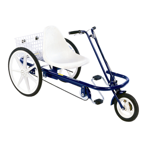
TRAILMATE DESOTO HAULER User manual

DESOTO HAULER
OWNER'S GUIDE


DESOTO HAULER PART LIST ^ TRACTOR SEAT "OPTIONAL
* COASTER BREAK KIT #12111
ITEMS #65 thru #77
Item Part # Description Qty. Item Part # Description Qty.
111871 REFLECTOR KIT 140 11805 HANDLEBAR, HI RISE 1
212199 SCREW #14 x 3/4 441 11801 GRIP BLACK 7/8 1pr
320080 PLATFORM REAR WELDMENT 142 11813 STEM, HANDLEBAR 1
412102 FLAG SAFETY W/POLE 143 12188 SCREW 10X3/8 TYPE B SHH 1
512241 SET COLLAR 5/8 144 20213 SEAT POST CLAMP 1-1/8" STL CP 1
611171 WASHER, 1-1/2 x 5/16 445 19720 NUT 5/8-18 NYLON INSERT 2
712246 3/16 SQUARE KEY X 5/8 146 20126 SNAP RING / RR140062 2
819869 AXLE DRIVE W/2KEYWAYS 247 12076 POST 9" SEAT 1
912240 WASHER SPACER 448 12212 SCREW 5/16-18X1-1/2 HHCS 1
10 11894 SEAT WESTERN SADDLE DESOTO 149 11898 BRACKET, WESTERN SADDLE 1
11 12175 NUT 5/16-18 FLANGED 450 12066 ^ BRACKET "L" REGAL 2
12 14272 FRAME REAR ST COLOR 151 12214 ^ SCREW 5/16-18X1-3/4 HHCS 2
13 20158 WHEEL, 24"X1.75"ALLOY FRONT 152 12208 ^ SCREW 5/6-18X3/4 HHCS 2
14 19590 TIRE, 24"X2.125" BSW W/ TUBE 353 12068 ^ BRACKET SEAT MOUNTING REGAL 1
15 11985 RIMSTRIP24"X1.75" 354 11900 ^ SEAT, REGAL TRACTO
R
1
16 20159 WHEEL,24"X1.75"X ALLOY REAR 255 11718 DECAL - TM HEAD 1
17 18714 SCREW 8X1/2 PAN PHIL 156 14089 DECAL - AVOID SHARP TURNS 1
18 11708 CHAINGUARD DESOTO ST COLOR 157 19325 DECAL - DO NOT STAND ON CYCLES 1
19 11857 PEDALS, 1/2" 1pr 58 20118 DECAL - HEFTY HAULER 1
20 13198 SCREW GROMMET 159 11719 DECAL - TM CHAINGUARD 1
21 11643 BEARING AXLE 99502HNR 460 11729 DECAL - SEAT TUBE 1
22 12218 CARRIAGE BOLT 3/8-16X3/4 461 12172 NUT 1/4-20 FLANGED 1
23 12075 SISSY BAR DESOTO ST COLOR 162 12227 SCREW 1/4-20 X 1- " HHCS 1
24 12178 NUT 3/8-16 FLANGE 463 12232 WASHER 1/4 SAE 1
25 18643 CHAIN/CL DES 93 P CB/3SP 1 64 11952 * Solid Sprocket 22T 1
26 14268 FRAME DESOTO FRONT ST COLOR 1 65 11667 * Hub CB Trike w/ 22 Weld Spkt. 1
27 11697 CRANK BEARING SET, COMPLETE 1 66 18986 * Washer Anti-Turn S/A 2
28 11934 SPROCKET 36T 1/2X1/8 1 67 12240 * Washer Spacer 8
29 11695 CRANK 5-1/2" (24" TRIKE) 1 68 19153 * Nut Axle CB 2
30 11679 CONNECTING LINK 2 69 12170 * Nut, 10-32 /star 1
31 11747 FENDER '24" MWT FRONT 1 70 12193 * Screw,10-32 x 1 1
32 11764 FENDER BRACE 24" MWT 1 71 12239 * Spacer, cb/3spcb 13rso62550 1
33 12176 NUT5/16-24 HEX 2 72 11684 * Chain / Cl Des/ Reg 37P CB/3SP 1
34 12301 WASHER 3/8 SAE FLAT 2 73 11071 * Set Screw, 5/16-18 x 3/4 Sq. Hd. 2
35 20012 KEY SQUARE 3/16 x 1-1/4 2 74 18909 * Hub Sprocket 21 Tooth 1/2 X 1/8 1
36 20297 BRAKE CANTILEVER CABLE, NOOD 3 75 12238 * Washer 3/8 USS 3
37 20019 BRAKE-V CANTILEVER COMPLETE 1 76 12428 * Washer 3/8 Internal Tooth Drv 2
38 19337 FORK 24" MWT CANTILEVE ST COLOR 1 77 18667 FORK WHEEL RETAINER 2
39 11831 HEAD SET, COMPLETE 1
TOOLS NEEDED
HAMMER 1/2" WRENCH 9/16" WRENCH
3/8" WRENCH PLIERS 5/32" ALLEN WRENCH
FLATHEAD SCREWDRIVER AIRPUMP HAMMER
PHILLIPS SCREWDRIVER AIR GAUGE 15/16 WRENCH
#20216 11.02.07
11/28/2007 8:47 AM G:\CYCLE MANUAL CHANGES\DesRegal Hauler\20216 part list 1102.07.xls

DESOTO HAULER
ASSEMBLY INSTRUCTION
1. Preparation
Remove all parts from the frame and wheel cartons.
Check air pressure and inflate tires to 35 psi. Make
sure tires are properly seated on rims.
2. Rear Frame and Wheels
Loosen set collar (5) on the axles inside the
transmission box. Slide set collars to the end of the
axles and retighten. Slide the axles outward for wheel
installation.
Install drive and non drive side wheels. Align wheel-
axle keyways and tap 1-1/4” key square (35) into
keyways. Install washer (67), and 5/8” nylon lock nut
(45) on axles.
IMPORTANT; Make certain the axle thread fully
engages the nylon locking portion of nut. Loosen axle
set collar, remove all axle endplay, and tighten set
collar.
Install non-drive side wheel. Install washer (67) and
5/8” nylon lock nut (45) on axle. IMPORTANT;
make certain the axle thread fully engages the nylon
locking portion of nut. Loosen non-drive wheel set
collar, remove all axle endplay, and retighten set collar
(5).
If there is any side-to-side movement of the axles,
loosen setscrew in collars, slide collars to eliminate
excess side movement, and retighten setscrews.
3. Frame Assembly
Slide front frame (26) into rear frame (12) with
transmission box open side down, as far as possible.
Install two 3/8” carriage bolts (22) through the slots in
the sides of the transmission box from the outside
inward. Be sure the square shoulders of the bolts seat
into each slot. Install flange nuts (24); do not tighten
at this time.
4. Front Fender and Wheel
Install front wheel in the slots in the fork. Install fork
wheel retainers (59); make certain the tabs on the
washers are seated into the holes in the fork. Insert
bolt through center hole in fork. Slide the fender
bracket over the bolt, install washer & hand tighten
nut. Place the fender brace (32) over wheel axle
ends. Install washers (34) & nuts (33) on wheel
axle.
Check that the wheel is centered between the fork
blades; tighten nuts.
5. Pedals
To install pedals (19), screw the pedal marked “R”
into the right side of the crank in a clockwise
direction. Install the left pedal (marked “L”) by
turning in a counter-clockwise direction. Use a
9/16” open-end wrench to tighten.
6. Chain
Install drive chain (25) over front and rear sprockets
and join together with connecting link (30). Install
connecting link, and spring clip, using pliers. Slide
the frame section apart, evenly, until the chain is
tight (approximately 3/4” total up and down chain
movement at middle is permissible) and securely
tighten all four rear frame bolts. Rotate the pedal
several times to check that the chain is running
freely.
-KEEP FINGERS CLEAR!
If binding is encountered, the chain may have to be
loosened until the binding is eliminated. Chain
binding is usually the result of a sprocket
misalignment. Repositioning the sprocket on the
rear axle, or re-squaring the trike rear to the front
frame section can correct this.
7. Chain Guard
To install chain guard (18), place over chain and
slide rear of guard under top of transmission box.
When the plastic screw grommet (20) on the rear of
the guard is lined up with the slotted hole in the side
of transmission box, secure with screw (17). Before
tightening it is necessary to line up the holes in the
front mounting bracket. Remove and reinstall
screw (43) and tighten. Tighten the rear screw. Turn
the pedals to make sure the chain does not rub on
the chain guard. If the chain rubs, adjust the back
or front mounting bracket to obtain clearance.

DESOTO HAULER
Assembly Instructions
2
8a. Western Saddle Seat
To install western saddle seat (10), secure sissy bar
(23) to the two 5/16” studs on the underside of the
seat. The sissy bar should be installed so the top curves
to the rear of the trike.
Remove the seat-mounting bracket (49) (it is loosely
installed on the seat post) and install on the two
remaining studs on the bottom of the seat. You will
need to use a 1/2” socket wrench to reach the nut.
Secure the seat mounting bracket and seat to the seat
post (47) using any of the four sets of holes with the
1-1/2” long screw (48) and nut (11). NOTE: The four
sets of holes in the seat-mounting bracket will
determine the distance from the handlebar. You may
have to reposition later. Attach the sissy bar long
slotted holes to the two tabs welded to the axle
housing. Install carriage bolts (22) and attach nuts
(24). DO NOT tighten at this time.
Seat Adjustment
Loosen clamp hardware (44) on the seat post and raise
seat to desired height. DO NOT expose more than 6-
1/2” of seat post. Pull up on back of seat until level.
Tighten seat post clamp and sissy bar bolts securely.
NOTE: The four sets of holes in the seat-mounting
bracket allow 3-1/4” front/back adjustment to the
handlebar. Reposition height & front back setting for
rider’s maximum comfort.
9. Handlebar
Slide the handlebar (40) through the clamp on the stem
(42) with the portion containing the long bolt to the
rear of handlebar. Install clear reflector. Install the
stem into the fork (38) until the line marked on the
stem is not visible. Align handlebar to the fork as it
faces straight ahead and tighten bolt in stem firmly.
DO NOT over tighten; this can damage the fork tube.
CAUTION: Check that head set (39) is tight.
DO NOT over tighten, however, as this can damage
the fork bearings. Fork assembly should rotate freely.
Slide handbrake lever onto right side of handlebar and
tighten lightly. Slide hand grips (41) on handlebar until
they bottom out. A small amount of soapy water inside
the grip will make installation much easier. NEVER
use oil or other lubricants! Slide handbrake lever
against grip, adjust position and secure tightly.
10. Cantilever Brake Installation,
and Adjustment
The front V-brake cantilever pad assembly comes
attached to front fork. Unwrap the brake lever cable
and insert the “ball” end into round slot in the brake
lever. Slide open end of cable through cable guide.
Install cable guide into cable guide holder.
Slide cable boot onto cable (open end first).
Feed the brake cable wire through the hole on the
lock bolt (the cable clamp) and snugly tighten the
clamp. Pull the slack out of the cable so that the
brake pad faces are within 1/8” of the wheel rim &
tighten. Refer to cantilever v-brake setup for final
adjustment.
11. Platform
Place platform (3) onto rear frame, center between
the rear wheels and immediately behind the sissy
bar. Using sheet metal screws (2), secure the basket
to the two holes in the rear frame crossover tube and
two rear holes in the top of the transmission box.
Tighten screws with a 3/8” socket wrench.
12. Reflectors and Safety Flag
*Steel Spoke Wheels
Install the clear wheel reflectors by placing between
the spokes, as near the rim as possible. Locate the
spoke in the reflector groove and secure with the
plastic rivet-clip provided into reflector bolt bag.
Repeat for other wheels.
Place the Safety Flag (4) in flag holder on the
platform frame.
13 Final Check
Review the instructions, check connecting bolts and
screws for tightness, and readjust the seat and
handlebar as necessary.
Table of contents
Other TRAILMATE Bicycle manuals
TRAILMATE
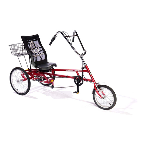
TRAILMATE Meteor User manual
TRAILMATE
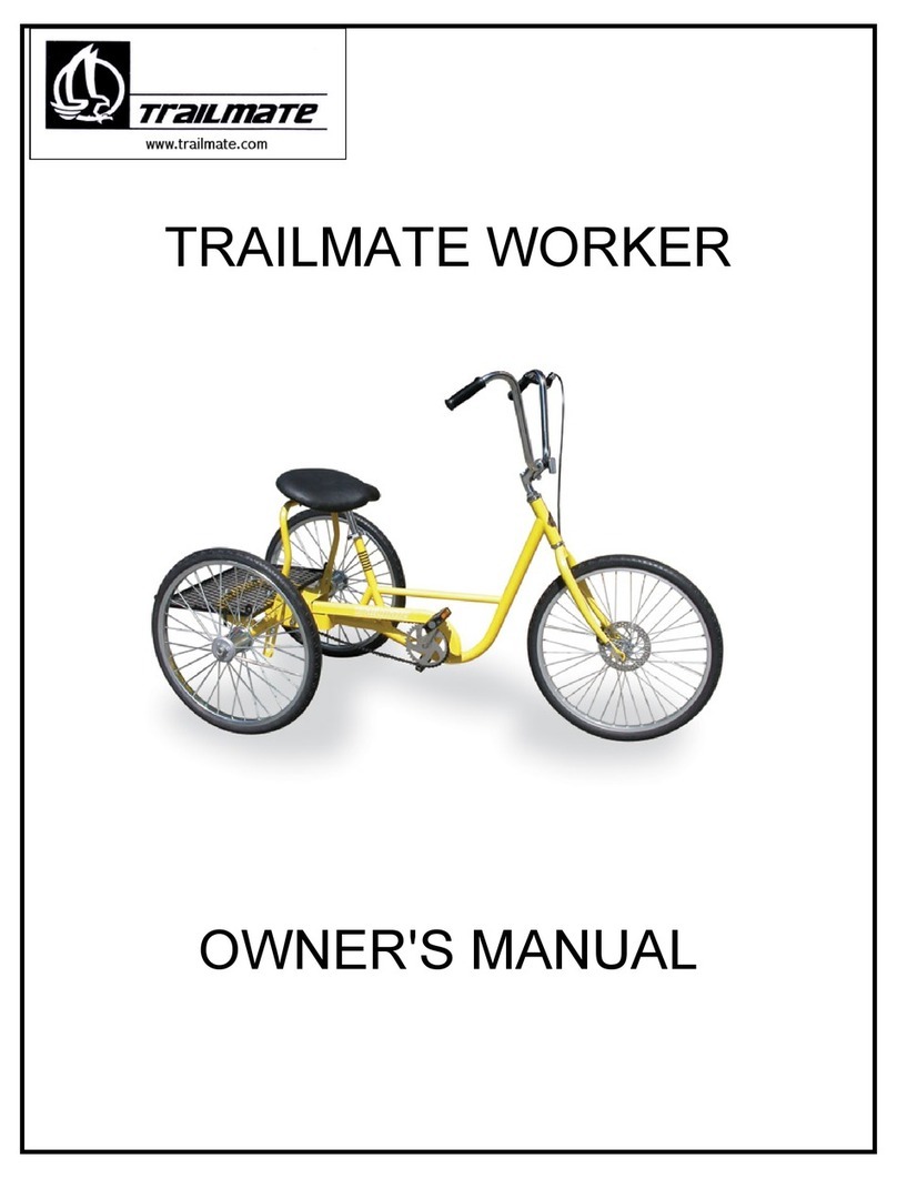
TRAILMATE Worker User manual

TRAILMATE
TRAILMATE Desoto Hauler User manual
TRAILMATE
TRAILMATE FUN CYCLE User manual

TRAILMATE
TRAILMATE Desoto Classic User manual

TRAILMATE
TRAILMATE Low Rider User manual

TRAILMATE
TRAILMATE DOUBLE JOYRIDER User manual
TRAILMATE
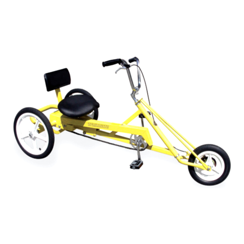
TRAILMATE JUNIOR LOW RIDER User manual

TRAILMATE
TRAILMATE FUN CYCLE User manual
TRAILMATE
TRAILMATE JOYRIDER User manual
