manuals.online logo
Brands
  1. Home
  2. •
  3. Brands
  4. •
  5. Trane
  6. •
  7. Controllers
  8. •
  9. Trane Tracer SC User manual

Trane Tracer SC User manual

3
1
2
SAFETY WARNING
Only qualified personnel should install and service the equipment. The installation,
starting up, and servicing of heating, ventilating, and air-conditioning equipment
can be hazardous and requires specific knowledge and training. Improperly
installed, adjusted or altered equipment by an unqualified person could result in
death or serious injury. When working on the equipment, observe all precautions in
the literature and on the tags, stickers, and labels that are attached to the
equipment.
© 2020 Trane
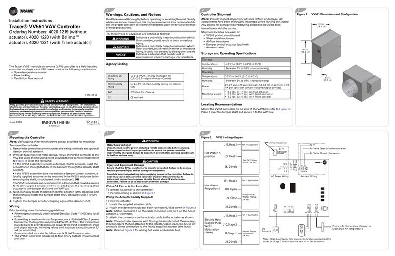
Order Number: BMSC000AAA01100
Warnings, Cautions, and Notices
Read this manual thoroughly before operating or servicing this unit.
Safety advisories appear throughout this manual as required. Your
personal safety and the proper operation of this machine depend upon
the strict observance of these precautions.
Packaged Contents
Required Tools
• 5/16 in. (8 mm) slotted screwdriver
• 1/8 in. (3 mm) slotted screwdriver
The three types of advisories are defined as follows:
WARNING Indicates a potentially hazardous situation
which, if not avoided, could result in death or
serious injury.
CAUTION Indicates a potentially hazardous situation
which, if not avoided, could result in minor or
moderate injury. It could also be used to alert
NOTICE Indicates a situation that could result in
equipment or property-damage only accidents.
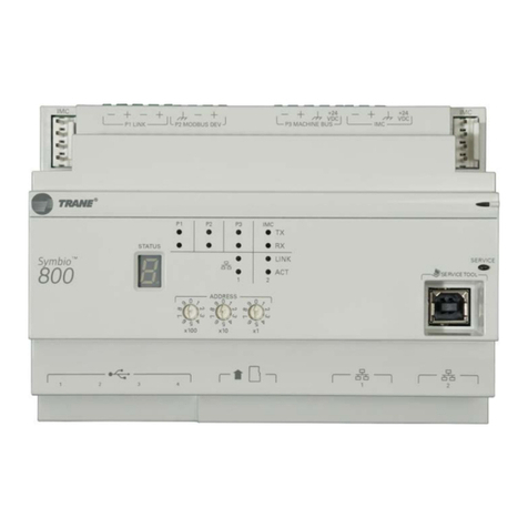
One (1) Tracer SC module
(controller) One (1) Power supply module (PM014)
Two (2) 4-position terminal block
plugs Six (6) 3 position terminal block plugs
One (1) LON termination kit Two (2) 2 position terminal block plugs
One (1) Installation sheet One (1) IMC power cable 3 in. (75 mm)
long
One (1) phone cable
Mounting and Removing the Tracer SC and the
Power Supply Module
• The mounting location must meet the temperature and humidity
specifications as outlined in Table 1.
• Do not mount on a flat surface, such as on a floor or on top of a table.
Mount in an upright position with the front facing outward.
To mount the Tracer SC or the power supply module:
1. Hook the top half of the Tracer SC onto the DIN rail.
2. Gently push on the lower half of the Tracer SC until the release clip
snaps into place.
3. Hook the top half of the power supply module onto the DIN rail next
to the Tracer SC.
4. Gently push lower half of power supply module until the release clip
snaps into place.
WARNING
Hazardous Voltage!
Disconnect all electrical power, including remote disconnects, before
servicing. Follow proper lockout/tagout procedures to ensure the power
cannot be inadvertently energized. Failure to disconnect power before
service could result in death or serious injury.
snap
Mounting the Tracer SC
(or the power supply
module)
Removing or Repositioning the Tracer SC or the
Power Supply Module
To remove or reposition the Tracer SC or the power supply module:
1. Insert a screwdriver into the slotted release clip and gently pry
upward on the clip with the screwdriver, OR;
If the screwdriver fits the slot size, insert the screwdriver into the
slotted release clip and rotate it to the left or right to release tension
on the clip.
2. While holding tension on the slotted release clip, lift the Tracer SC (or
power supply module) upward to remove or reposition.
3. If repositioning, push on the Tracer SC (or power supply module) until
the slotted release clip snaps back into place.
Removin
g the
TracerSC
December 2020 BAS-SVN215J-EN
Installation Instructions
Tracer®SC System Controller
with PM014 Supply Module
X3641154-01

4
6
©2020 Trane
Trane has a policy of continuous product and product data improvement and reserves
the right to change design and specifications without notice. We are committed to using
environmentally conscious print practices.
Trane - by Trane Technologies (NYSE: TT), a global climate innovator - creates
comfortable, energy efficient indoor environments for commercial and residential
applications. For more information, please visit trane.com or tranetechnologies.com.
Wiring and Applying Power
1. Connect one end of the provided IMC power cable to the IMC connection on the Tracer SC.
Connect the other end of the IMC power cable to the IMC connection on the power supply module.
2. Wire the 24 Vac input connection to a dedicated 24 Vac, Class 2 transformer.
3. Ensure the PM014 is properly grounded.
Important: This device must be grounded for proper operation! The factory-supplied ground
wire must be connected from any chassis ground connection on the device ( ) to
an appropriate earth ground ( ). The chassis ground connection can be the 24 Vac
transformer input at the device, or any other chassis ground connection on the
device.
Note: Neither the Tracer SC nor the PM014 is grounded through the DIN rail connection.
4. Apply power to the Tracer SC by pressing the power button.
All status LEDs illuminate and the following sequence flashes on the 7-segment display:
8, 7, 6, 5, 4, L, dancing dash pattern. The dancing dashes continue while the Tracer SC
is operating normally.
Note: For more information see “Tracer SC Installation and Setup Guide,” BAS-SVX31,
and “Power Supply Module PM014 Installation, Operation, and Maintenance”, BAS-SVX33.
PM014
24
VAC
XFMR
OUT
24
VAC
24
VAC
XFMR
OUT
24
VAC
Tracer SC
IMC
connections
Note: A pigtail connection
should be used between the
chassis ground on the
device and an earth ground,
if the device is not grounded
through one leg of the
transformer wiring.
24 Vac output 24 Vac input
IMC cable
PM014
24 Vac Transformer
Specifications
Agency Listings and Compliance
The European Union (EU) Declaration of Conformity is available from
your local Trane®office.
Table 1. Tracer SC Specifications
Power Requirements
(From PM014) 24 Vdc @ 0.3A; 14VA max (PM014 input VA).
Storage
Temperature: -40°C to 70°C (-40°F to 158°F)
Relative humidity: Between 5% to 95% (non-condensing)
Operating Environment
Temperature: -40°C to 50°C (-40°F to 122°F)
Humidity: Between 10% to 90% (non-condensing)
Input power: 24 Vac
Product weight 1 kg (2.2 lb.)
Altitude: Maximum 2,000 m (6,500 ft.)
Installation: Category 3
Pollution Degree 2
BAS-SVN215J-EN 11 Dec 2020
Supersedes X39641154-01H (Mar 2016)
Tracer SC front panel
power
button 7-segment
display

Other manuals for Tracer SC

1

Other Trane Controllers manuals

Trane Symbio 210 Installation and operating instructions

Trane

Trane Symbio 210 Installation and operating instructions

Trane Tracer TD7 User manual

Trane

Trane Tracer TD7 User manual

Trane Tracer UC600 Quick setup guide

Trane

Trane Tracer UC600 Quick setup guide

Trane CONTH01AAUTOA Assembly instructions

Trane

Trane CONTH01AAUTOA Assembly instructions

Trane Tracer UC600 User manual

Trane

Trane Tracer UC600 User manual

Trane Tracer ZN511 Owner's manual

Trane

Trane Tracer ZN511 Owner's manual

Trane Tracer MP581 Manual

Trane

Trane Tracer MP581 Manual

Trane IPG315D User manual

Trane

Trane IPG315D User manual

Trane Tracer ZN511 User manual

Trane

Trane Tracer ZN511 User manual

Trane Tracer VV550 Installation and operating instructions

Trane

Trane Tracer VV550 Installation and operating instructions

Trane Tracer UC400 User manual

Trane

Trane Tracer UC400 User manual

Trane Tracer CH535 User manual

Trane

Trane Tracer CH535 User manual

Trane Tracer ZN510 Owner's manual

Trane

Trane Tracer ZN510 Owner's manual

Trane TR1 6002 User manual

Trane

Trane TR1 6002 User manual

Trane Symbio 210 Installation and operating instructions

Trane

Trane Symbio 210 Installation and operating instructions

Trane Tracer ZN.520 User manual

Trane

Trane Tracer ZN.520 User manual

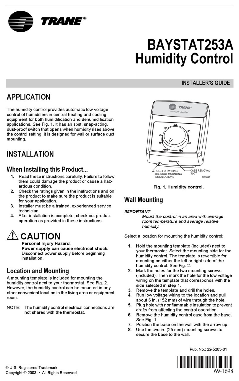
Trane BAYSTAT253A Assembly instructions

Trane

Trane BAYSTAT253A Assembly instructions

Trane Tracer AH540 Setup guide

Trane

Trane Tracer AH540 Setup guide

Trane VariTrane VAV-SVX02B-EN Owner's manual

Trane

Trane VariTrane VAV-SVX02B-EN Owner's manual

Trane TR150 Operating instructions

Trane

Trane TR150 Operating instructions

Trane Tracer AH541 Instruction Manual

Trane

Trane Tracer AH541 Instruction Manual

Trane Thermo King CANAIRE User manual

Trane

Trane Thermo King CANAIRE User manual

Trane 700 Use and care manual

Trane

Trane 700 Use and care manual

Trane Tracer CH535 User manual

Trane

Trane Tracer CH535 User manual

Popular Controllers manuals by other brands

LEGRAND 5 720 89 manual

LEGRAND

LEGRAND 5 720 89 manual

Kelly KLS-RM Series user manual

Kelly

Kelly KLS-RM Series user manual

Emerson Fisher 1305 Series installation guide

Emerson

Emerson Fisher 1305 Series installation guide

Johnson Controls VA-9070 Series Technical bulletin

Johnson Controls

Johnson Controls VA-9070 Series Technical bulletin

AMX NX-2200 quick start guide

AMX

AMX NX-2200 quick start guide

stellar labs MK-16 RGBWT user manual

stellar labs

stellar labs MK-16 RGBWT user manual

Danfoss VLT5000 SyncPos operating instructions

Danfoss

Danfoss VLT5000 SyncPos operating instructions

Neousys Technology Nuvo-2021+ user manual

Neousys Technology

Neousys Technology Nuvo-2021+ user manual

Omron SYSMAC CPM2B-S001M-DRT Operation manual

Omron

Omron SYSMAC CPM2B-S001M-DRT Operation manual

Val Controls IHP24 Troubleshooting

Val Controls

Val Controls IHP24 Troubleshooting

Wintriss SmartPAC PRO Servo user manual

Wintriss

Wintriss SmartPAC PRO Servo user manual

Conrad 64 05 52 operating instructions

Conrad

Conrad 64 05 52 operating instructions

Feniex FLASHER H-2220 manual

Feniex

Feniex FLASHER H-2220 manual

Yamaha RCX142 user manual

Yamaha

Yamaha RCX142 user manual

Regulus IR 14 CTC instruction manual

Regulus

Regulus IR 14 CTC instruction manual

SpaNet SV2 Installation & technical manual

SpaNet

SpaNet SV2 Installation & technical manual

LOVATO ELECTRIC RGK600 installation manual

LOVATO ELECTRIC

LOVATO ELECTRIC RGK600 installation manual

Emerson Fisher 627 Series instruction manual

Emerson

Emerson Fisher 627 Series instruction manual

manuals.online logo
manuals.online logoBrands
  • About & Mission
  • Contact us
  • Privacy Policy
  • Terms and Conditions

Copyright 2025 Manuals.Online. All Rights Reserved.