manuals.online logo
Brands
  1. Home
  2. •
  3. Brands
  4. •
  5. Trane
  6. •
  7. Electric Heater
  8. •
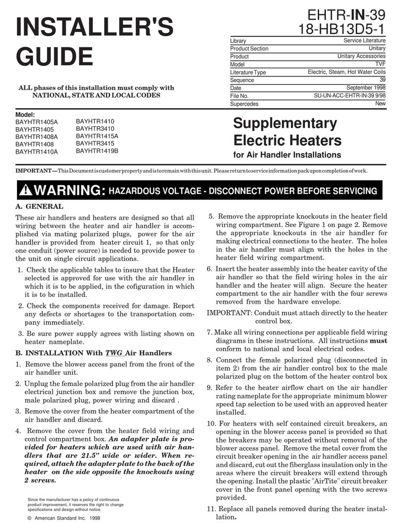
  9. Trane BAYHTR1405000 Assembly instructions

Trane BAYHTR1405000 Assembly instructions

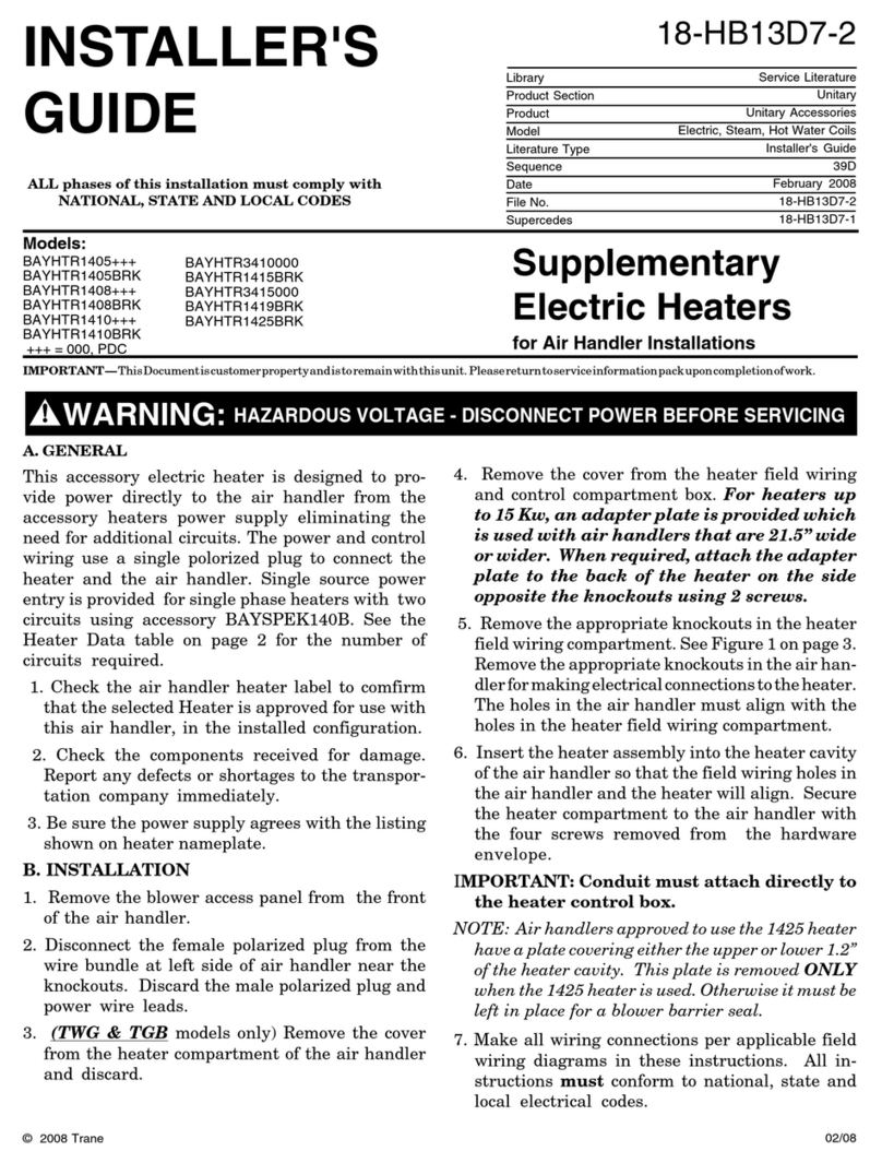
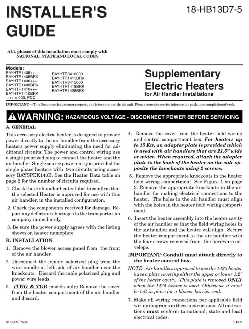
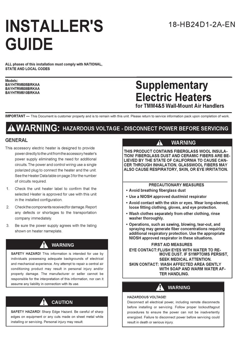
Supplementary
Electric Heaters
for Air Handler & Modular Blower Installations
INSTALLER'S
GUIDE
Models:
BAYHTR1405+++
BAYHTR1405BRK
BAYHTR1408+++
BAYHTR1408BRK
BAYHTR1410+++
BAYHTR1410BRK
+++ = 000, PDC
BAYHTR3410000
BAYHTR1415BRK
BAYHTR3415000
BAYHTR1419BRK
BAYHTR1425BRK
IMPORTANT—ThisDocumentiscustomerpropertyandistoremainwiththisunit. Pleasereturn to service information packuponcompletionofwork.
© 2009 Trane
GENERAL
This accessory electric heater is designed to provide
power directly to the unit from the accessory heat-
ers power supply eliminating the need for additional
circuits. The power and control wiring use a single
polarized plug to connect the heater and the unit.
Single source power entry is provided for single
phase heaters with two circuits using accessory
BAYSPEK140B. See the Heater Data table on page
2 for the number of circuits required.
1. Check the unit heater label to confirm that the
selected Heater is approved for use with this unit
in the installed configuration.
2. Check the components received for damage. Re-
port any defects or shortages to the transportation
company immediately.
3. Be sure the power supply agrees with the listing
shown on heater nameplate.
INSTALLATION
1. Remove the blower access panel from the front
of the unit.
2. Disconnect the female polarized plug from the
wire bundle at left side of unit near the knockouts.
Discard the male polarized plug and power wire
leads.
3. Remove the cover from the heater field wiring and
control compartment box. For heaters up to 15
Kw, an adapter plate is provided which is
used with units that are 23.5” wide or wider.
ALL phases of this installation must comply with
NATIONAL, STATE AND LOCAL CODES
When required, attach the adapter plate to
the back of the heater on the side opposite the
knockouts using 2 screws.
4. Remove the appropriate knockouts in the heater
field wiring compartment. See illustration on page
3. Remove the appropriate knockouts in the unit
cabinet for making electrical connections to the
heater. The holes in the unit cabinet must align
with the holes in the heater field wiring compart-
ment.
5. Insert the heater assembly into the heater cavity
of the unit so that the field wiring holes in the
unit and the heater will align. Secure the heater
compartment to the unit with the four screws
removed from the hardware envelope.
IMPORTANT: Conduit must attach directly to the heater control
box.
NOTE: Units approved to use the 1425 heater have
a plate covering either the upper or lower 1.2” of the
heater cavity. This plate is removed ONLY when the
1425 heater is used. Otherwise it must be left in place
for a blower barrier seal.
6. Make all wiring connections per applicable field
wiring diagrams in these instructions. All instruc-
tions must conform to national, state and local
electrical codes.
7. Connect the female polarized plug (disconnected
in item 2 from the wire bundle next to the knock-
outs) to the male polarized plug on the bottom of
the heater control box.
18-HB13D7-7
HAZARDOUS VOLTAGE - DISCONNECT POWER BEFORE SERVICING
WARNING:
05/09
Page 2
INSTALLER'S GUIDE
18-HB13D7-7
BAYHTR -- HEATER DATA
Heater
Model No.
Number
of
Circuits
Phase
240 VOLT 208 VOLT
Capacity Heater
Amps per
Circuit
Capacity
Heater
Amps per Circuit
KW BTUH KW BTUH
BAYHTR1405 +++ 1 1 4.80 16400 20 3.60 12300 17.3
BAYHTR1408 +++ 1 1 7.68 26200 32 5.76 19700 27.7
BAYHTR1410 +++ 1 1 9.60 32800 40 7.20 24600 34.6
BAYHTR3410 000 1 3 9.60 32800 34.6 7.20 24600 30
BAYHTR1415 BRK 2 1 15.36 52400 40/24 11.53 39300 34.6/20.8
BAYHTR3415 000 1 3 15.36 52400 38.2 11.53 39300 33.1
BAYHTR1419 BRK 2 1 19.20 65500 32/48 14.42 49200 27.7/41.6
BAYHTR1425 BRK 3 1 24.96 85200 44/40/20 18.73 63900 38.1/34.6/17.3
+++ = 000, BRK, PDC
000 = pigtails, BRK = contains Circuit Breakers, PDC = contains Pull Disconnect
8. Refer to the heater minimum airflow chart on
the unit rating nameplate for the appropriate
minimum blower speed tap to be used with the
approved heater installed.
9. For heaters with self contained disconnect, an
opening in the blower access panel is provided
so that the disconnect may be operated with-
out removal of the blower access panel. Open
the plastic "AirTite" disconnect cover in the
front panel opening by loosening the screw on
the cover door. Cut out the fiberglass insula-
tion only in the area where the disconnect will
extend through the opening.
10.Replace all panels removed during the heater
installation.
IMPORTANT:The BAYHTR** electric heat accessory, designed
for use with this unit, may include up to a combination of three
30 and / or 60 amp circuit breakers to provide an electrical dis-
connect for service personnel that are intended to help protect
internal electrical components in the event of a short circuit or
ground fault. As designed, the circuit breakers supplied in the
BAYHTR* accessory do not provide over-current protection of
the branch circuit. Therefore, the branch circuit(s) shall be sized
and protected according to the unit nameplate.
Page 3
INSTALLER'S GUIDE
18-HB13D7-7
SIDE ENTRANCE
NOTE 2
NOTE 1
FOR HEATER ELECTRICAL
CONNECTIONS
NOTE 1
NOTE 2
FOR HEATER ELECTRICAL
CONNECTIONS
TOP ENTRANCE
RESISTANCE HEATER
CONTROL BOX
POLARIZED PLUG
LEADS FROM AIR HANDLER
CONTROL BOX (SEE NOTE 3)
BLOWER ACCESS PANEL
CABINET
ADAPTER
PLATE
NOTES
1. HEATER LINE VOLTAGE KNOCKOUT LOCATIONS FOR 1" OR
1-1/2" CONDUIT. CONDUIT MUST BE ATTACHED DIRECTLY TO
THE HEATER CONTROL BOX.WIRE AND CONDUIT SIZE MUST
COMPLY WITH N.E.C.
2. HEATER LINE VOLTAGE KNOCKOUT LOCATIONS FOR 3/4" OR
1-1/4" CONDUIT. CONDUIT MUST BE ATTACHED DIRECTLY TO
THE HEATER CONTROL BOX.WIRE AND CONDUIT SIZE MUST
COMPLY WITH N.E.C.
3. BLOWER CIRCUIT POWER SUPPLY LEADS & LOW VOLTAGE
HEATER CONTROL LEADS FROM UNIT CONTROL BOX ARE
CONNECTED TO THE HEATER VIA A POLARIZED PLUG.
Page 4
INSTALLER'S GUIDE
18-HB13D7-7
Trane
6200 Troup Highway
Tyler,Tx 75707-9010
Since the manufacturer has a policy of continuous product and product data improvement, it reserves the right to change design and specification without notice.
MINIMUM HEATING AIRFLOW CFM - HEATER MATRIX
AIR HANDLER /MODULAR BLOWER MINIMUM HEATING AIRFLOW CFM - HEATER MATRIX
MODEL NUMBER
1405 000
BRK
PDC
4.80kw
1408 000
BRK
PDC
7.68kw
1410 000
BRK
PDC
3410 000
9.60kw
1415 BRK
15.36kw
3415 000
15.36kw
1419 BRK
19.20kw
1425
BRK
24.96kw
NUMBER OF HEATER RACKS 1 2 2 3 3 4 5
TWG018A L / L L / M L / H -- -- -- --
TGB3F18 / TGB3F25 / TWG025A L / L L / M L / M L / H L / H -- --
TGB3F30 / TWG030A L / L L / L L / L L / M L / M -- --
TGB3F36 / TWG036/037A L / L L / L L / L L / M L / M -- --
TBG3F42 / TWG042A L / L L / L L / L L / H L / H -- --
TWG048A L / L L / L L / L L / H L / H L / M --
TGB3F48 / TWG060A L / L L / L L / L L / L L / L L / M --
TEC / TWE018C L / L L / M L / M -- -- -- --
TEC / TWE024C L / L L / L L / L L / M L / M -- --
TEC / TWE030C L / L L / L L / L L / M L / M -- --
TEC / TWE036C L / L L / L L / L L / L L /L PS --
TEC / TWEO42C L / L L / L L / L L / H L /H AS --
TWE048C L / L L / L L / L L / L L / L L / H L / H
TEC3F48 L / L L / L L / L L / L L / L L / H
TWE060C/D AS L / L L / L L / L L / L L / H L / H
TEC3F60 L / L L / L L / L L / L L / H
4TEP/TWE018P L / L L / M L / M -- -- -- --
4TEP/TWE024P L / L L / L L / L L / M L / M -- --
4TEP/TWE030P L / L L / L L / L L / M L / M -- --
4TEP/TWE036P L / L L / L L / L L / H L / H L / H --
4TEP/TWE042P L / L L / L L / L PS PS L / H --
4TEP/TWE048P L / L L / L L / L PS PS L / H L / H
TWE060P L / L L / L L / L PS PS L / H L / H
4TEP/TWE063P L / L L / L L / L PS PS L / H L / H
TEE3D/TEE3F/TWE031E 700/1000 700/1000 700/1000 700/1125 700/1125 1000/1350 --
TEE3D/TEE3F/TWE037E 600/700 600/900 600/900 1000/1300 1000/1300 1000/1350 --
TEE3D/TEE3F/TWE040E 600/1100 600/1100 600/1100 1100/1400 1100/1400 1100/1400 1100/1400
TEE3D/TEE3F/TWE049E 700/1400 700/1400 700/1400 1400/1600 1400/1600 1400/1600 1400/1600
TEE3D/TEE3F/TWE065E 900/1500 900/1500 900/1500 1200/1800 1200/1800 1200/1800 1200/1800
TWE062E 900/1500 900/1500 900/1500 1200/1800 1200/1800 1200/1800 1200/1800
2TEE3C31 1000/1130 PS/AS 1130/1350 1130/1350 1130/1350 1130/1350 --
2TEE3C37 600/900 900/1100 1100/1450 1100/1450 1100/1450 1100/1450 --
2TEE3C40 PS/AS 600/900 900/1100 1100/1400 1100/1400 1100/1400 1100/1400
2TEE3C49 800/1100 800/1100 800/1400 1100/1700 1100/1700 1400/1700 1400/1700
2TEE3C65 900/1200 900/1200 1200/1500 PS/AS PS/AS 1200/1500 1500/1800
4TEE3C01/4TEE3D01 1000/1130 PS/AS 1130/1350 1130/1350 1130/1350 1130/1350 --
4TEE3C02/4TEE3D02 600/900 900/1100 1100/1450 1100/1450 1100/1450 1100/1450 --
4TEE3C03/4TEE3D03 PS/AS PS/AS 900/1100 PS/AS PS/AS PS/AS --
4TEE3C04/4TEE3D04 PS/AS PS/AS 900/1100 PS/AS PS/AS PS/AS --
4TEE3C05/4TEE3D05 PS/AS 600/900 900/1100 1100/1400 1100/1400 1100/1400 1100/1400
4TEE3C06/4TEE3D06 800/800 PS/AS PS/AS PS/AS PS/AS PS/AS PS/AS
4TEE3C07/4TEE3D07 800/1100 800/1100 800/1400 1100/1700 1100/1700 1400/1700 1400/1700
4TEE3C08/4TEE3D08 900/900 PS/AS PS/AS PS/AS PS/AS PS/AS PS/AS
4TEE3C09/4TEE3D09 900/1200 900/1200 1200/1500 PS/AS PS/AS 1200/1500 1500/1800
4TEE3C10/4TEE3D10 900/1200 900/1200 1200/1500 PS/AS PS/AS 1200/1500 1500/1800
TEE3F29 900/900 900/900 900/900 900/1400 900/1400 PS/PS --
TEE3F48 800/800 800/800 800/800 AS/AS AS/AS AS/AS AS/AS
TEE3F64 900/900 900/900 900/900 AS/AS AS/AS 900/900 900/1800
4TBE0C04 900/900 900/900 900/1100 PS/1100 PS/1100 PS/PS --
4TBE0C08 900/900 900/PS 900/PS PS/1200 PS/1200 PS/PS AS/PS
COOLING / HEAT PUMP
AIRFLOW
AS = Heater application is af-
fected based on whether the
outdoor unit is a heat pump
or cooling unit.
PS = Minimum speed tap
varies based on unit installa-
tion position.
SEE UNIT NAMEPLATE OR
PRODUCT DATA FOR
AS/PS NOTES
MODEL
NUMBERS
000 = pigtails, BRK = con-
tains circuit breakers, PDC =
contains pull disconnect
This manual suits for next models

13

Other Trane Electric Heater manuals

Trane BAYHTRS309 User manual

Trane

Trane BAYHTRS309 User manual

Trane BAYHTR1405 Series Assembly instructions

Trane

Trane BAYHTR1405 Series Assembly instructions

Trane BAYHTR1405A Assembly instructions

Trane

Trane BAYHTR1405A Assembly instructions

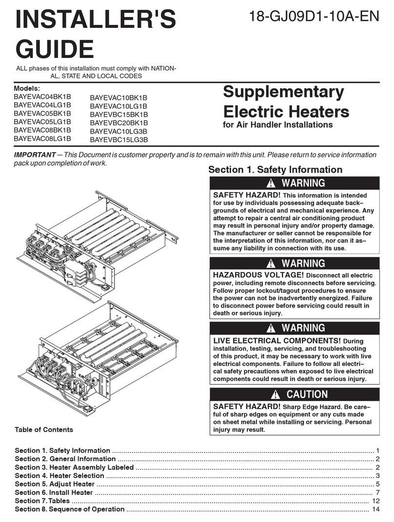
Trane BAYEVAC04BK1B Assembly instructions

Trane

Trane BAYEVAC04BK1B Assembly instructions

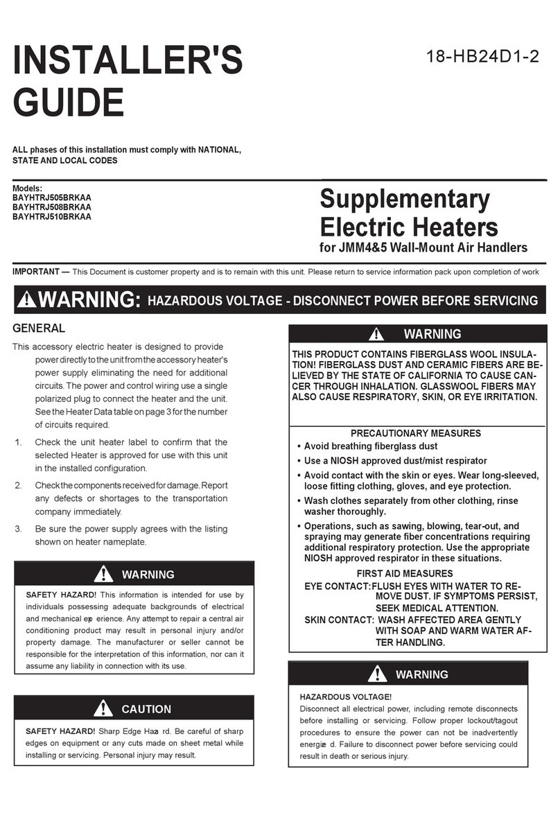
Trane BAYHTRM505BRKAA Assembly instructions

Trane

Trane BAYHTRM505BRKAA Assembly instructions

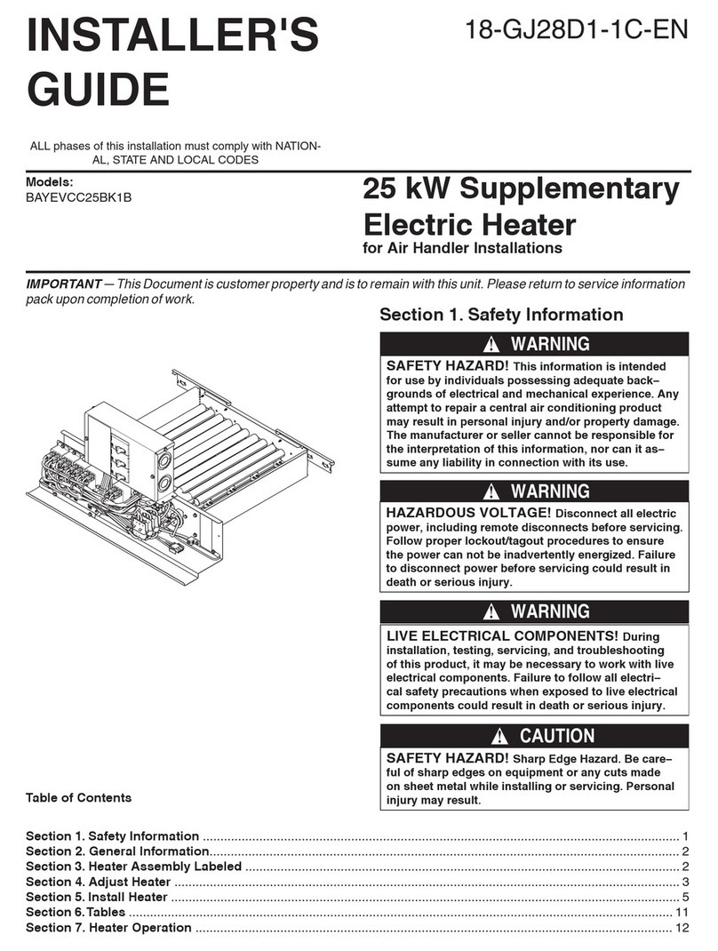
Trane BAYEVCC25BK1 Assembly instructions

Trane

Trane BAYEVCC25BK1 Assembly instructions

Trane BAYECAA05LG1B Assembly instructions

Trane

Trane BAYECAA05LG1B Assembly instructions

Trane OXBOX BAYHTRJ505BRKAA Assembly instructions

Trane

Trane OXBOX BAYHTRJ505BRKAA Assembly instructions

Trane CAB-PRC001-EN User manual

Trane

Trane CAB-PRC001-EN User manual

Trane BAYEVCC25BK1A Assembly instructions

Trane

Trane BAYEVCC25BK1A Assembly instructions

Trane BAYHTRS309 Assembly instructions

Trane

Trane BAYHTRS309 Assembly instructions

Trane BAYEVAC05LG1A Assembly instructions

Trane

Trane BAYEVAC05LG1A Assembly instructions

Trane BAYHTR1405 Series Assembly instructions

Trane

Trane BAYHTR1405 Series Assembly instructions

Popular Electric Heater manuals by other brands

Frico AC Corinte ACCS20 Original instructions

Frico

Frico AC Corinte ACCS20 Original instructions

Daikin Modular L Series Assembly instructions

Daikin

Daikin Modular L Series Assembly instructions

Adax Norel LM Series manual

Adax

Adax Norel LM Series manual

SUNWIND 421275 instruction manual

SUNWIND

SUNWIND 421275 instruction manual

Fostoria SUN-MITE FES-1024-1CA manual

Fostoria

Fostoria SUN-MITE FES-1024-1CA manual

Goldair Ecosave GECO204 operating instructions

Goldair

Goldair Ecosave GECO204 operating instructions

Bionaire BQH308C Instruction leaflet

Bionaire

Bionaire BQH308C Instruction leaflet

Rointe Sierra aqua TSIA 28B180 Series instruction & installation guide

Rointe

Rointe Sierra aqua TSIA 28B180 Series instruction & installation guide

MaxxGarden 21027 user manual

MaxxGarden

MaxxGarden 21027 user manual

Desa Tech HEATERS owner's manual

Desa

Desa Tech HEATERS owner's manual

Armstrong ES180 SERIES installation instructions

Armstrong

Armstrong ES180 SERIES installation instructions

Harvia DELTA COMBI Instructions for installation and use

Harvia

Harvia DELTA COMBI Instructions for installation and use

Dimplex DX 512E Installation and operating instructions

Dimplex

Dimplex DX 512E Installation and operating instructions

Sahara 1500W Hanging Electric Heater quick start guide

Sahara

Sahara 1500W Hanging Electric Heater quick start guide

Dyson AM04 operating manual

Dyson

Dyson AM04 operating manual

KAJO TH2-30NB-CNR manual

KAJO

KAJO TH2-30NB-CNR manual

Bizroma BHHD40F instruction manual

Bizroma

Bizroma BHHD40F instruction manual

Dimplex DLG1058 owner's manual

Dimplex

Dimplex DLG1058 owner's manual

manuals.online logo
manuals.online logoBrands
  • About & Mission
  • Contact us
  • Privacy Policy
  • Terms and Conditions

Copyright 2025 Manuals.Online. All Rights Reserved.