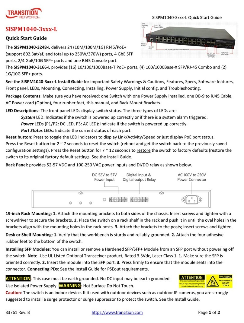
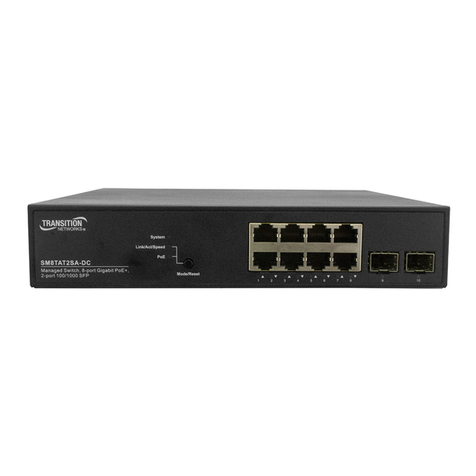
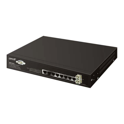
SMxxTAT4Xx Quick Start Guide
33784 Rev. B https://www.transition.com Page 4of 4
Installation
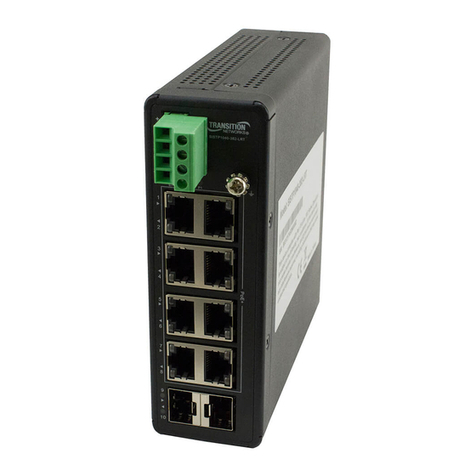
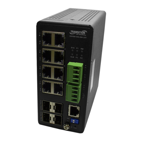
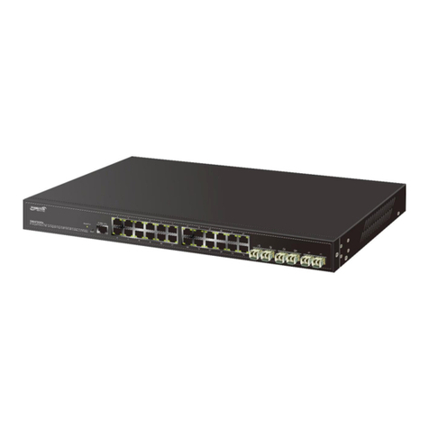
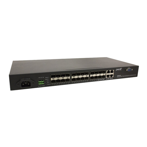
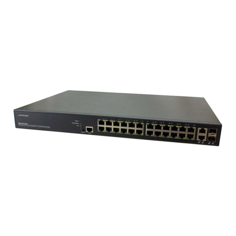
Package Contents: Carefully unpack the switch from the packaging and verify you received one Switch, one AC
Power cord, four rubber feet, this document, two 19" Ear Rack Brackets, 8 Screws, 2 screws for power plate
cover, one DB9F to RJ45 Plug Console Cable, EPE for PSU (x2, -RP only), and one Post card.
Mount Switch in a 19-inch Rack: 1. Attach the mounting brackets to both sides of the chassis. Insert screws and
tighten then with a screwdriver to secure the brackets. 2. Place the switch on a rack shelf in the rack. Push it in
until the oval holes in the brackets align with the mounting holes in the rack posts. 3. Attach the brackets to the
posts. Insert screws and tighten them.
Mount Switch on Desk or Shelf: 1. Verify that the workbench is sturdy and reliably grounded. 2. Attach the four
adhesive rubber feet to the bottom of the switch.
Install SFP+ Modules:. 1. Position the SFP device at either installation slot, with the SFP label facing up on upper
SFP slots or down on lower SFP slots. 2. Carefully slide the SFP device into the slot, aligning it with the internal
installation guides. 3. Press firmly so that the SFP device is firmly seated. 4. Attach an appropriate cable into the
SFP module port. 5. Attach the other end of the cable to the other device.
Connect Powered Devices (PDs): Note: this device does not comply with IEEE 802.3at at 48-51.4 VDC, or with IEE
802.3bt at 48-53.4 VDC. The latest device label indicates:802.3af: 48-57VDC. 802.3at: 52-57VDC. 802.3bt: 54-
57VDC. This device drops ~1.3V from Vin to PSEout. IEEE requires PSEout voltages at the PSE output into the
cable: 802.3af: 44VDC. 802.3at: 50VDC. 802.3bt: 52VDC. Not meeting this PSEout requirement may cause power
up failures or power cycling with devices drawing the maximum power with maximum cable loss.
Connect the AC Power Cord: 1. Connect the AC power cord to the AC power receptacle of switch. 2. Connect the
other end of the AC power cord to the AC power outlet. 3. If the SYS LED is ON, the power connection is correct.
Redundant Power (SM48TAT4XA-RP Only): The SM48TAT4XA-RP supports two power supplies for power
redundancy. 1. Use a screw driver to remove the power plate cover. 2. Carefully insert the new Power Supply into
the chassis slot until the Locking Lever clicks. 3. See “Connecting the AC Power Cord”. 4. Save the power plate
cover and screws for possible future use.
Power Supply: The PS-AC-920 Secondary power supply provides redundant power support (920 Watts).
CAUTION! Hazardous Area: Do Not remove this cover. Trained service people only. No serviceable components
inside. LEDs: DC OK and AC OK LEDs on the power supply front panel.
Procedure:If using only one power supply, it can be installed in either power supply bay, and the Face Plate must
be installed in the other bay. 1. Remove the blank Face Plate to use the one open Power Supply slot.
Save the Face Plate and screws. 2. Carefully insert the Power Supply into the chassis until the Locking Lever clicks.
3. Fasten the AC Power Supply with the Mounting Screws (and Power Cord Retainer, if used). 4. Continue with
“Connecting the AC Power Cord” on the next page. Note: This product is to be connected only to UL listed PoE
networks and without routing to the outside plant.
Initial Switch Config via Web Browser: See the Web User Guide.
Initial Switch Config via CLI: 1. Use an RJ-45 cable to connect a terminal or PC/terminal emulator to the switch
port to access the CLI. 2. Attach the RJ-45 serial Console port on the switch front panel to the cable for Telnet/CLI
configuration. 3. Attach the other end of the DB-9 cable to a PC running Telnet or a terminal emulation program
such as HyperTerminal or TeraTerm. 4. After powering up the switch for the first time, you can perform the initial
switch configuration using the CLI. See the
CLI Reference
for details.
Related Information: For TN Drivers, Firmware, etc. go to the Product Support webpage (logon required). For TN
Manuals, Brochures, Data Sheets, etc. go to the Support Library (no logon required).
Transition Networks: 10900 Red Circle Drive | Minnetonka, MN 55343, U.S.A. | tel: +1.952.941.7600 | toll free:
customerservice@transition.com |
