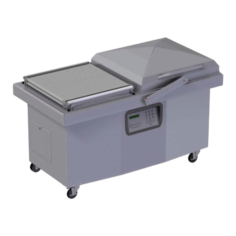
Transpak MINI-VERTI TP-202MV Guide

Original Instruction
TP-202MV
PALLET
TP-202MV
TP-202MVB (with battery)
SEMI-AUTO
MINI VERTI
07/2017

PART I
CONTENTS
1. Safety Instructions ..............................................................................1
2. Construction and Units .......................................................................3
3. General Safety Remarks .....................................................................5
4. Machine Information ..........................................................................7
5. Operating the Machine .......................................................................20
6. Adjustment .........................................................................................22
7. Maintenance .......................................................................................23
8. Troubleshooting Guide .................................................................. …28
9. Wiring Diagram ............................................................................. …30

-1 -
1. Safety Instructions
THIS MANUALGIVES YOU INFORMATION ON SAFETY INSTRUCTIONS,
SPECIFICATIONS, OPERATION AND MAINTENANCE OF STRAPPING
MACHINES.
BEFORE OPERATING OR SERVICINGTHE MACHINE, PLEASE REVIEW THE
ENTIRE MANUALAND FOLLOW THE SAFETY INSTRUCTIONS CAREFULLY.
(1) Before Operating
a. Verify that the power line voltage is correct.
b. The machine must be properly grounded to avoid a shock hazard. All wiring must be in
accordance with local wiring standards.
c. The strapping machine can only be operated with polypropylene (P.P.) strapping; do not
use polyester (PET) strapping or polyethylene (PE) cord strap.
(2) During Operation
a. The height of the package should not be less than 280mm (11.06").
b. Check if the machine emits any smokes or unusual sound when it is running.
(3) After operating
a. Remove dust and dirt from the unit.
b. Turn off the power when the machine is not in use.
(4) Signs
(5) Maintenance
a. Turn off the power before removing either of the covers.
b. Use the correct tools and parts to repair the machine.
c. The heater tongue is very hot; do not touch it.
Caution!
Electric Shock Hazard
Caution!
Hot!
Do not touch!

-2 -
(6) Storage
a. The store room must be dry.
b. Do not expose the machine to extreme cold or heat environment.
c. Place the machine on an even floor in order to avoid any distortion.
(7) Other Reminders
a. Do not alter or bypass protective interlocks.
b. An operation manual must remain attached to the machine at all times.
c. Do not alter the equipment or circuitry unless authorized to do so by the manufacturer.
d. Do not operate the machine with the covers removed.
e. Never put any part of your body near, under or into a moving machine.
f. Do not overload the machine by exceeding the performance limitations specified in this
manual.

- 3 -
2. Construction and Units
a. TP-202MV
3 Reel unit
Holds the strap coil.
(If the reel core size is 280mm,
you can take off the center
drum to have core size
200mm.)
4 Body frame group
2 Bandway unit
(Sword unit & RH Bandway ass'y)
5 Electric control unit
1 Strapping head unit
This unit is the most important part of the
machine for cutting and sealing P.P. strap.

- 4 -
b. TP-202MVB
3 Reel unit
Holds the strap coil.
(If the reel core size is 280mm,
you can take off the center
drum to have core size
200mm.)
4 Body frame group
2 Bandway unit
(Sword unit & RH Bandway ass'y)
1 Strapping head unit
This unit is the most important part of the
machine for cutting and sealing P.P. strap.
5 Electric control unit
6 Battery unit

- 5 -
3. General Safety Remarks
(1) Basic Operation
The manual and the safety remarks are to be read before use. The operation manual should
be kept with the machine at all times for regular maintenance and inspections.
This machine was built with state of the art technology and rigid adherence to safety
standards.
Unless used properly, it can cause injury to operators or persons in close proximity to the
machine. In addition, improper use can cause damage to the machine or property around the
machine.
(2) Basic Safety Precautions
The user is to be instructed in all other generally applicable legal and other mandatory
regulations relevant to accident prevention and environmental protection in addition to the
operating instructions.
For safety reasons, long hair must be tied back or otherwise secured, garments must be close
fitting and no jewelry may be worn.
Use protective equipment whenever required by circumstances or by law.
Carefully observe all safety instructions and warnings attached to the machine and make
sure that they are always complete and perfectly legible.
Always make certain that persons being trained and instructed in working on or with the
machine are permanently supervised by an experienced person.
Work on the electrical system and equipment of the machine is only to be carried out by a
skilled electrician or by persons under the supervision and guidance of a skilled
electrician and in accordance with the rules and regulations of electrical engineering.
(3) Safety Instructions Governing Specific Operational Phases
Avoid any operation mode that might be unsafe.
All necessary precautions to ensure that the machine is only used being in a safe and reliable
state are to be taken. The machine is only to be operated if all protective and safety
devices, including removable safety devices, emergency shut-off equipment,
noise-protection elements and exhaust systems are in right place and fully functional.
The machine is to be checked for damage and defects at least once per work shift. Any
changes including the working behavior of the machine are to be reported to competent
persons immediately. If necessary, the machine is to be stopped and locked immediately.

- 6 -
In case of any malfunction the machine must be stopped and locked until the defect has been
eliminated.
Generally make sure that nobody is at risk before starting up the machine.
All personnel that will be operating this machine should be thoroughly trained in all phases
of operation and safety.
Always tighten unscrewed connections after maintenance and repair.
After completing maintenance and repair, all safety devices removed for setting up or
repairing the machine must be reinstalled and checked for functionality prior to putting the
machine back into service.
To minimize the environmental impact, all consumables and replaced parts must be
disposed of safely.
Before starting the machine, check that the accessories have been stowed away safely.
Do not attempt any operation that may be a risk to the stability of the machine.
(4) Warning of Electrical Dangers
Immediately remove power to the machine in case of trouble in the electrical system.
Replace a fuse with one with the same style and ratings; pay particular attention to matching
the specified current.
Any electrical work performed on the equipment must be conducted by a skilled electrician
or under the supervision of a skilled electrician. All work must be observed good electrical
engineering practice and follow safety rules and local wiring standards.
Inspect the electrical equipment of the machine at regular intervals. Tighten any loose
connections. Check wiring for scorch marks; replace scorched wiring and determine and
correct the reason for the overheating.
When working on live equipment, ensure that a second person is available to cut power in
case of an emergency. When appropriate, secure the working area with safety tape and a
warning sign. Use insulated tools for electrical work.
Before working on high-voltage assemblies, turn off the power supply. Carefully discharge
the supply cable and short-circuit any energy-storage components such as capacitors.
If the equipment was moved, carefully refit and refasten all parts removed for transport
before reapplying power.
Before moving the machine, remember to disconnect the power cable.

- 7 -
(5) Grounding Instructions Shall Include the Following:
This product must be grounded. In the event of an electrical short circuit, grounding
reduces the risk of electric shock. This product is equipped with a cord that has a
grounding wire and an appropriate grounding plug. The plug must be plugged into an
outlet that is properly installed and grounded in accordance with all local codes and
ordinances.
If repair or replacement of the cord or plug is necessary, connect the ground wire to the
ground terminal of the plug. The wire with green insulation (with or without yellow stripes)
is the grounding wire.
Check with a qualified electrician or service person if the grounding instructions are not
clear or if in doubt about the proper grounding of the machine. Do not modify the plug
provided; if it will not fit the power outlet, have the proper outlet installed by a qualified
electrician.
This product is designed for use on a nominal 120 (230) volt AC circuit and has a grounding
plug.
DANGER!
Improper installation of the grounding can result in electrocution.
4. Machine Information
(1) Areas ofApplication and Machine Description
This plastic strapping machine can be used for a wide range of applications where the
minimum package height is at least 280mm.
This machine is particularly suitable for vertical low volume pallet strapping applications.
Machine Description
Semi-automatic plastic strapping machine for use with polypropylene strapping.
Heavy duty construction.
Simple, safe and user-friendly operation.
With light weight and compact size, it is easy to move beside the pallet you want to strap.
Handle is with feeding switch to feed the strap to the required length.
Environment Information
The strapping machine shall be installed in the following conditions:
Supply voltage: 0.9 - 1.1 nominal supply voltage
Source frequency: 0.99 - 1.01 nominal frequency
Ambient temperature: 5°C - 40°C (41℉-104℉).
Relative humidity: not exceed 50% at 40°C.
Please provide a suitable illumination around the machine for safety operation.

- 8 -
(2) The Safety Devices
This machine must only be operated with polypropylene strapping. The use of other
synthetic straps may produce hazardous substances to health.
Caution!
Power Switch (QS1).
This switch is lockable for safety.
Danger of burns near the heating unit! (1)
Dangerous points in the machine are covered by the screwed table top.
For safety reason, please take off the Sword Unit and put it by the machine body when the
machine is not operated, that is to prevent the people hitting or stepping the Sword Unit and
will make the Sword Unit damage.
For safety reason, make sure the Sword Unit do not be hit or crushed when moving the
machine.
(3) Electrical Specifications
System configuration:
1L+N+PE (Ground)
1L+N+PE (Ground)
Nominal power:
0.5 KW
0.5 KW
Rated current:
7A
10A
Rated voltage:
220V/230V/240V
110V
Rated frequency:
50Hz
60Hz
Type of current:
AC - single phase
AC - single phase

- 9 -
(4) Technical Data
a. TP-202MV
Sealing method
Heat
Strap width :
9 mm to 15.5 mm (3/8" to 5/8")
Strap reel diameter :
200 mm (8")
Strap reel diameter(OPTION) :
280 mm (11")
Width :
696 mm (27.4")
Depth :
2035 mm (80.1")
Electrical Requirement :
AC 110V/220V/230V/240V
(50/60Hz), 1PH
Weight :
85 kg (187 lbs.)
Noise emission :
78dB (A)
Ambient temp :
5℃~40℃(41℉~104℉)

- 10 -
b. TP-202MVB
Sealing method
Heat
Strap width :
9 mm to 15.5 mm (3/8" to 5/8")
Strap reel diameter :
200 mm (8")
Strap reel diameter(OPTION) :
280 mm (11")
Width :
696 mm (27.4")
Depth :
2459 mm (96.8")
Electrical Requirement :
AC 110V/220V/230V/240V (50/60Hz), 1PH
Weight :
183 kg (403 lbs.)
Noise emission :
78dB (A)
Ambient temp :
5℃~40℃(41℉~104℉)

- 11 -
(5) How to Remove/Handle the Machine from the Pallet
Two people stand on each side of the machine and remove the machine from the pallet to
the floor.

- 12 -
(6) Machine and Operating Elements
a.TP-202MV
(1) Power Switch
Supply the power when switch is ON.
(2) Feeding Length Knob
Strap is automatically fed according with the time preset by
the knob.
(3) Reset Button
To pull strap back into machine and/or to cut off strap.
(4) Strap Feed Button
To feed strap out of machine manually.
(5) Power Plug
To be connected to a 110V or 220V/230V/240V source.
(6) Strap Reel
Slide on strap coil here. (If the reel core is 280mm, you can
take off the center drum to have core size 200mm.)
(7) Brake
Stops the over-rotation of the strap reel.
(8) Strap Guide for Brake
Place strap on the Brake (7).
(9) Strap Bypass Guide
The strap is passed through this guide.
(10) Strap Feed Button
To feed strap out of machine manually.
(11) Sword Unit
To guide strap running through pallet.
(12) Weld cooling timer
To ensure good sealing efficiency under higher tension.

- 13 -
b. TP-202MVB
(1) Power Switch
Supply the power when switch is ON.
(2) Feeding Length Knob
Strap is automatically fed according with the time preset
by the knob.
(3) Reset Button
To pull strap back into machine and/or to cut off strap.
(4) Strap Feed Button
To feed strap out of machine manually.
(5) Power Plug
To be connected to a 110V or 220V/230V/240V source.
(6) Strap Reel
Slide on strap coil here. (If the reel core is 280mm, you
can take off the center drum to have core size 200mm.)
(7) Brake
Stops the over-rotation of the strap reel.
(8) Strap Guide for Brake
Place strap on the Brake (7).
(9) Strap Bypass Guide
The strap is passed through this guide.
(10) Strap Feed Button
To feed strap out of machine manually.
(11) Sword Unit
To guide strap running through pallet.
(12) Battery Unit
Supply the power through battery.
(13) Weld cooling timer
To ensure good sealing efficiency under higher tension.

- 14 -
c. UPS Operation Panel for TP-202MVB
(a) Power Switch:It's to activate UPS.
(b) LCD:It shows the potential of the battery.
(c) LED:It shows the operation status of UPS. Green light means the power
supply of either charging or strapping isn't from the battery but from the
power company.
Red light means the power supply of the operation is from the battery.
(d) Reset:To operate the machine with battery power, you must press the power
switch ○
afirst and then press “Reset”button for around 3 seconds.

- 15 -
(7) installation
a. TP-201MV
(a) Installation of Pushing Bar
○
1Please connect the wiring plug of the pushing bar to the terminal of machine.
Please refer to the illustration.
○
2Put the pushing bar to the 4 M6 screw holes and then hand tighten the 4 sets of
bolts (HBS0616N, SW06 & PW06A)
○
3Put the pushing bar support under the pushing bar and lock it onto pushing bar with
2 sets of M8 bolts and washers.

- 16 -
○
4Also tighten the pushing bar support to the frame with 2 sets of M8 bolts and
washers.
○
5Tighten the 4 sets of M6 bolts and washers that you just hand tighten on the step 2.
○
6After fixing the pushing bar, fasten the power cord with cable clamps
and screws TMS0408N on the pushing bar.

- 17 -
(b) Sword Assembling
Lock BandwayAss'y (LH) ○
1and Bandway Ass'y (RH) ○
2in place by FMS0610
○
3.
(c) Install the sword to the machine body
Fit the sword into the Block ○
4at the bottom of the machine until the sword is locked
in place. Make sure that the sword is hitched in with the hook ○
5.

- 18 -
b. TP-201MVB
(a) Installation of Pushing Bar
○
1Please connect the wiring plug of the
pushing bar to the terminal of machine.
Please refer to the illustration.
○
2Put the pushing bar to the 4 M6 Screw
holes and then hand tighten the 4 sets
of bolts and washers.
○
3Put the support bar under the pushing bar and lock it onto pushing bar with 2 sets of
M6 bolts and washers.
○
4Also tighten the support bar to the battery frame with 2 sets of M6 bolts and washers.
○
5Tighten the 4 sets of M6 bolts and washers that you just hand tighten on the
step ○
2.
pushing bar
pushing bar
support bar
pushing bar
support bar
This manual suits for next models
3
Table of contents
Other Transpak Packaging Equipment manuals

Transpak
Transpak Genesis TP-501 Instruction Manual

Transpak
Transpak MERCURY TP-702-59 Operation instructions

Transpak
Transpak TP-6000 Instruction Manual

Transpak
Transpak TP-6000-3 Guide

Transpak
Transpak Atlantis TP-701 Instruction Manual

Transpak
Transpak TP-201 Guide

Transpak
Transpak GENESIS HORI TP-502MH Guide

Transpak
Transpak TP-6000-1 Guide

Transpak
Transpak TP-201 Instruction Manual