10 IQVIEW8 Installation Instructions TG201232 Issue 9, 30-May-2017. Applies to v1.30.
IQVIEW8 Installation Instructions
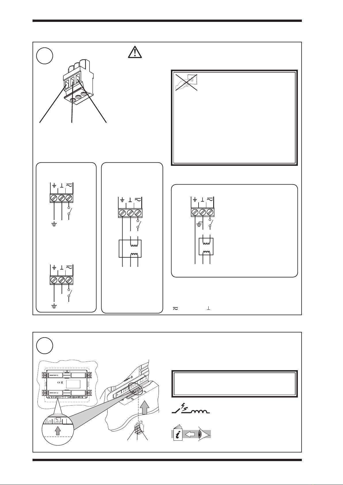
3Wire Power Connector
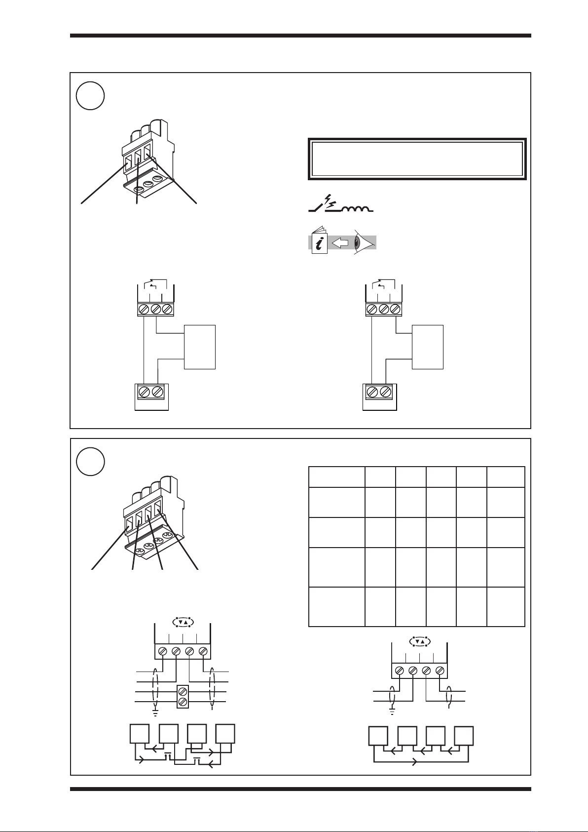
1Connect Relay Output (if required for alarm notication)
230 Vac/24Vac
transformer with isolated
output (e.g. ACC/24VAC)
General Connections
24 Vac
Some transformers are earthed (grounded) on one side of
the secondary. If so ensure the earthed (grounded) side is
connected to the central terminal of the power connector.
If the polarity of the connection is incorrect the unit will not
power up. If this happens swap the connections to the right
() and central ( ) terminals.
Terminal size 0.5 to 2.5
mm2(20 to 14 AWG)
3 2 1
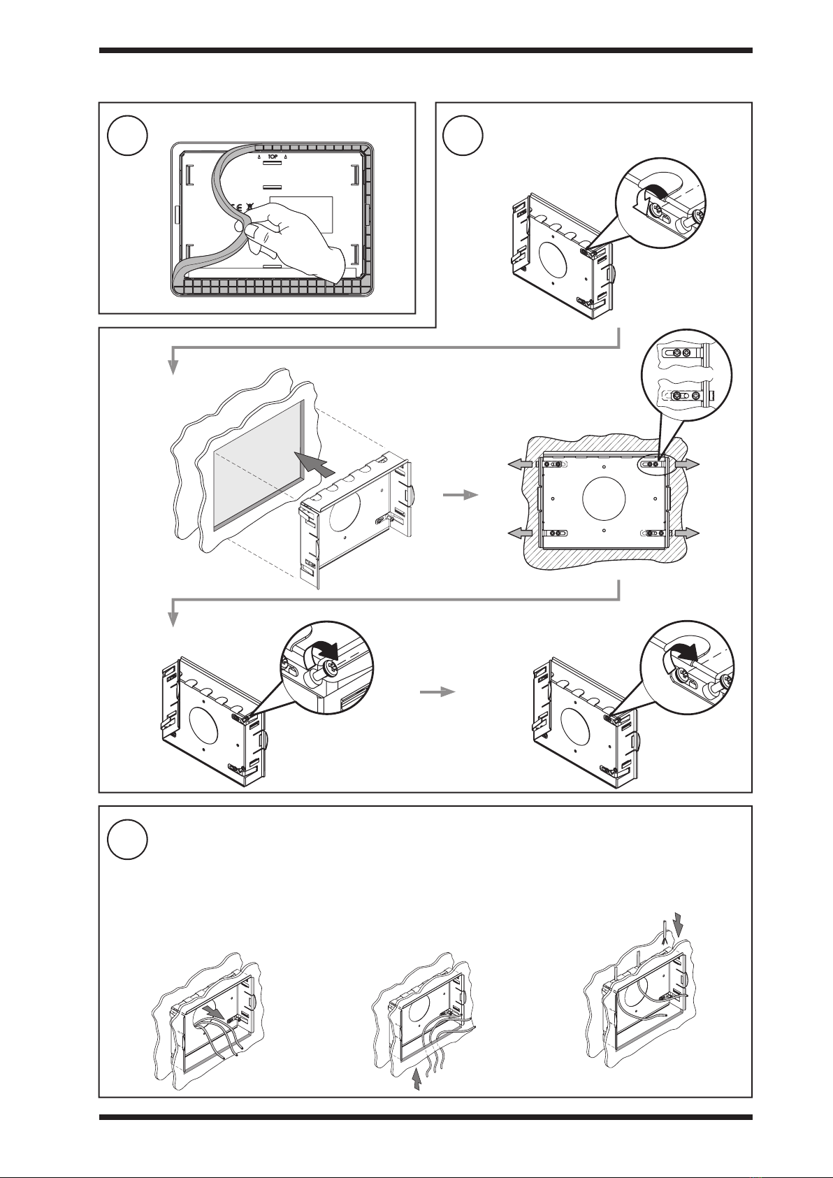
Important: Orientate connector
as shown.
O
I
DO NOT SWITCH ON POWER
Do not connect 230V input
power to this connector.
WARNING: This apparatus must be earthed (grounded)
via input supply earth (ground) terminal. The earth (ground)
on this unit is NOT a protective earth (ground), but it is
essential that an earth is tted for functional reasons.
Input power supply: The 24V supply must include a
suitably rated switch in close proximity and be clearly
marked as the disconnecting device for the unit. Do not
position the equipment so that the disconnecting device
is dicult to operate.
3.5 Installation - Wiring (continued)
3.6 Installation - Connect Cables
Do not connect 230V input
power to this connector.
SERVICE
13 14 15
16 17 18 19
RS232
24Va c
123
A
SERVICE
65 4
Terminal size 0.5 to 2.5 mm2(20 to 14 AWG)
654
24 Vdc
24 Va
24 Vac ±15% 50/60 Hz at 20 VA minimum
or 24 Vdc 440 mA, 10.5 W. For dc a dc supply with a minimum
output of 600 mA is recommended.
Note; The required power cannot be provided by a controller’s
auxiliary supply output; a separate supply is required.
Relay Output Arc Suppression
Installation Instructions (TG200208)
Arc suppression recommended.
Note: For UL rating the input power connections must be
made using 18 AWG or larger wire rated at least 90ºC.
For USA/Canada use a UL Listed,
Class 2, 24 Vac transformer
For USA/Canada use a
UL Listed, Class 2,
24 Vac transformer
For USA/Canada use a
UL Listed, Class 2,
24 Vac transformer
3 2 1
24 Vac/dc
ENL
230 Vac
24 Vac
3 2 1
24 Vac/dc
E N L
230 Vac
24 Vac
230 Vac/24 Vac transformer
with one side earthed
(grounded)