VIEWEG DV-5005DFS User manual

User manual
Screw Valve DV-5005DFS /-L
Dosier- und Mischtechnik
Version 2018/08-01

2
Manual Screw Valve DV-5005DFS /-L
Table of contents
1 Designated use
Dear Customer
Thank you for purchasing the screw valve DV-5005DFS.
For easy operating we developed this user manual.
Your Vieweg Team
The spindle valve DV-5005DSF is a revolutionary further development of conventional
spindle valves in order to solve the problems occurring there. Two-component material
is always a special challenge. Above all because it can completely destroy the valve by
hardening. Just as abrasive materials lead to high wear in the shortest possible time.
With the exchangeable material spindle, all these problems could be solved.
The precisely manufactured plastic spindle can be replaced quickly and easily. Cleaning
the valve is considerably simplified and is now no longer a time-consuming process.
No more expensive spare valves have to be in stock to keep lines running.
Replacement spindles are completely sufficient for this.
1 Designated use . . . . . . . . . . . . . . . . . . . . . . . . . . . . . . . . . . . . . . . . . . . . 2
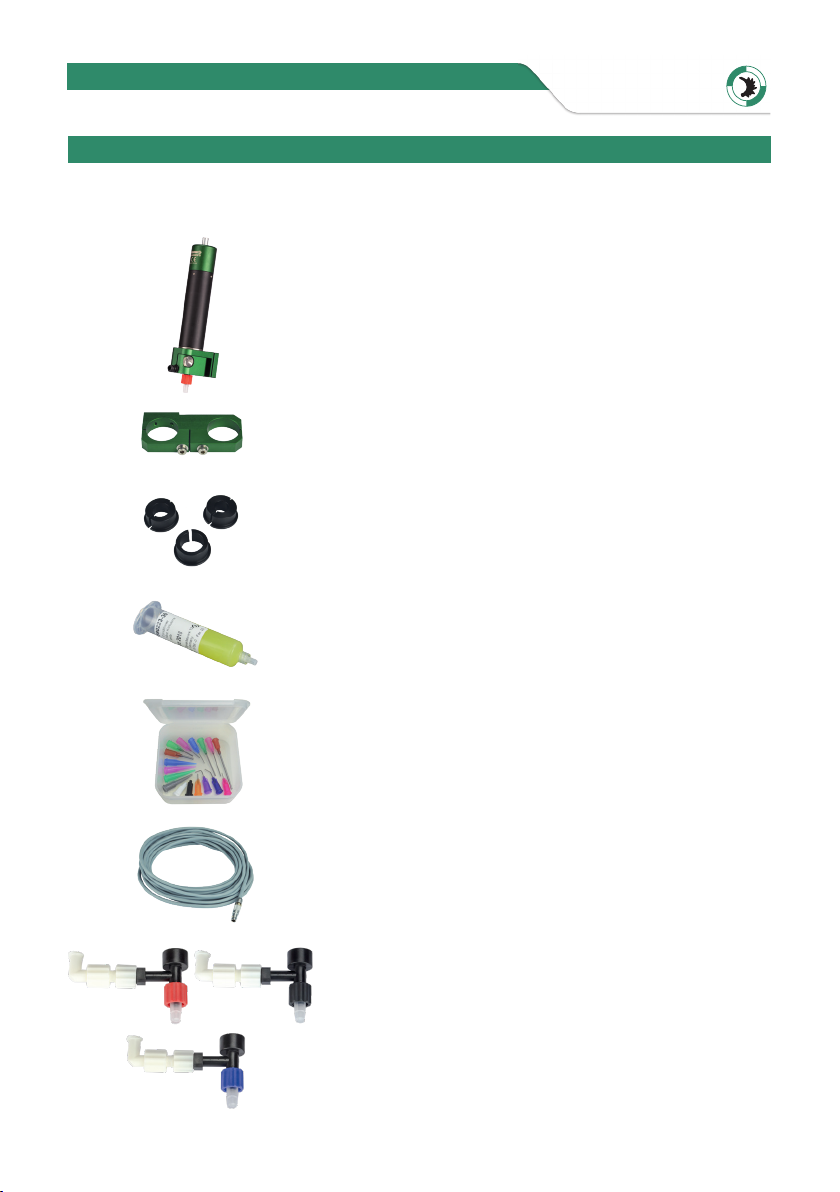
2 Scope of delivery . . . . . . . . . . . . . . . . . . . . . . . . . . . . . . . . . . . . . . . . . . . 3
3 Technical data . . . . . . . . . . . . . . . . . . . . . . . . . . . . . . . . . . . . . . . . . . . . . 4
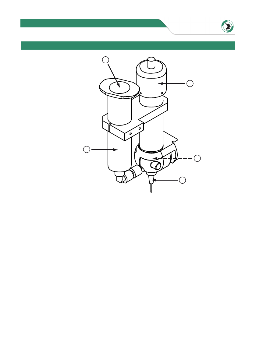
4 Part list . . . . . . . . . . . . . . . . . . . . . . . . . . . . . . . . . . . . . . . . . . . . . . . . . 4
5 Operating principle . . . . . . . . . . . . . . . . . . . . . . . . . . . . . . . . . . . . . . . . . 6
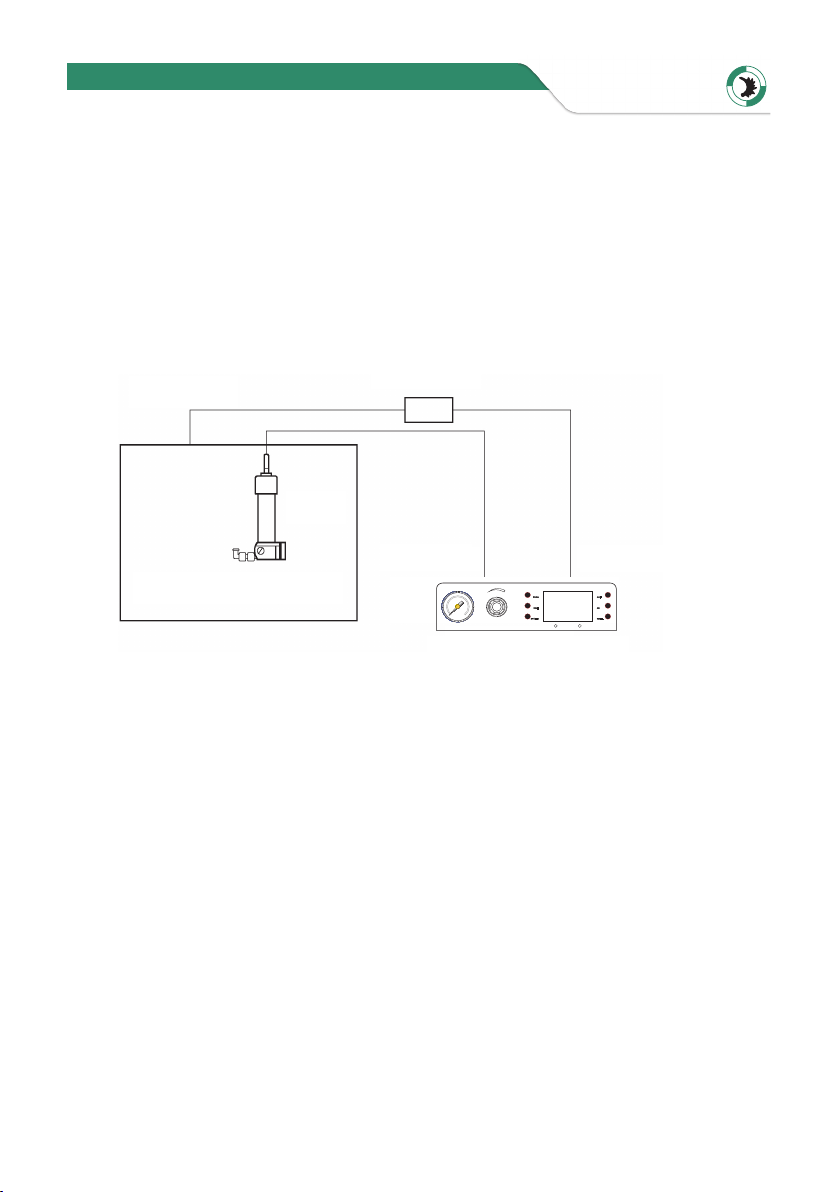
6 Installation . . . . . . . . . . . . . . . . . . . . . . . . . . . . . . . . . . . . . . . . . . . . . . . 7
6.1 Mechanical mounting . . . . . . . . . . . . . . . . . . . . . . . . . . . . . . . . . . 7
6.2 Electrical connection . . . . . . . . . . . . . . . . . . . . . . . . . . . . . . . . . . . 7
6.3 Compressed air supply . . . . . . . . . . . . . . . . . . . . . . . . . . . . . . . . . . 9
7 Commissioning . . . . . . . . . . . . . . . . . . . . . . . . . . . . . . . . . . . . . . . . . . . 10
7.1 Fill spindle with material . . . . . . . . . . . . . . . . . . . . . . . . . . . . . . . . 10
7.2 Installation of a new disposable spindle . . . . . . . . . . . . . . . . . . . . . . 10
8 Troubleshooting . . . . . . . . . . . . . . . . . . . . . . . . . . . . . . . . . . . . . . . . . . 10
VIEWEG

3
Manual Screw Valve DV-5005DFS /-L
The following parts are included in the scope of delivery:
Valve body
(Item.-No. DV-5005DFS or DV-5005DFS-L)
Barrel holder for screw valve
(Item.-No. V-0070)
Reducing rings
10 cc (Item.-No. 560943V)
5 cc (Item.-No. 561184V)
3 cc (Item.-No. 561183V)
30 cc conditioner in a syringe barrel
(Item.-No. 990223-30)
Dispensing tip set small
(Item.-No. 990062-K)
Connecting cable 4 m
(Item.-No. 990083)
Spindles with different pitch
6-pitch (Item.-No. DFS6-A)
8-pitch (Item.-No. DFS-8A)
16-pitch (Item.-No. DFS16-A)
2 Scope of delivery
VIEWEG
DFS8-ADFS6-A
DFS16-A

4
1
2
3
4
5
67
8
10
11
12
13
Manual Screw Valve DV-5005DFS /-L
Fig. 1
Motor voltage / power rating 24 V DC, 6 Watt
No load current (motor only) 60-70 mA
Starting current max. 1,5 A
Terminal resistance 21,6 Ohm
Size 153 x 40 x 34 mm
Weight 235 gr
Output shaft speed 400 U/min
Maximum air pressure requirement 20 psi
Wetted material path Acetal / PE
Material interface Luer-Lock adapter
Minimum material viscosity 50,000 cPs
4 Part list
3 Technical data
VIEWEG

5
Manual Screw Valve DV-5005DFS /-L
not shown
No. in Fig. 1 Description Item-No.
1Motor assembly V-0051
2* Valve housing DV-5005DFS, door right V-0090
2* Valve housing DV-5005DFS-L, door left V-0090-L
3Disposable path assembly (6-, 8- or 16-pitch DFS6-A /-8-A/-16-A
4Syringe bracket assembly V-0070
5Sample syringe
6Screw short, M3x8 V-0053
7Screw long, M3x25 V-0054
8Dispensing tip (e.g. from the disp. tip set) 990062-K
10 Panel screw V-0092
11* Door right V-0093
11* Door left V-0093-L
12 Elbow 90 deg. Luer-Lock-78
13 Luer-Lock male Luer-Lock-77
* depending on version
Tip cap V-0094
Connection socket Lemo V-0059
Square for motor shaft DV-5000DFS V-0060
Motor sleeve incl. flange for DV-5000DFS V-0061
Connection cable 4 m, plug - open ends 990083
Connection cable 4 m, 6 pin DIN plug 990083-DIN
Connection cable 4 m, 6 pin DIN plug 90 deg. 990083-DIN-90
Connection cable 4 m, plug 90 deg. - open ends 990083-90
Connection cable 4 m, plug on both sides 990083-VC1100
Plug Lemo, without cable V-0064
Axle for locking door V-0091
VIEWEG

6
1
4
5
3
2
Manual Screw Valve DV-5005DFS /-L
The DV-5000DFS dispenses fluid with a positive displacement action using a rotary feed
screw principle. Fluid material is held in a feed reservoir (1), see Figure 2, under a positive
head of air, between 1 to 20 psi (depending upon the viscosity of the material). This
positive air pressure, supplied by the air line (2), forces the fluid material out of the barrel
into the feed screw chamber (3) material flow from this point, to the dispense tip (4), is
controlled by the feed screw rotation in the feed direction. The feed screw is driven by
the motor. Applying a DC voltage signal to the motor (5), will rotate the feed screw and
the fluid will be forced out of the dispensing tip.
Shearing of the material is achieved by reverse Z-motion (tip retraction). When the mo-
tor stops, the unit remains in position for a fraction of a second (dwell) to allow the last
of the material to flow out of the dispensing tip. After the dwell period, the automation
equipment moves the DV-5000DFS Valve to the next position.
5 Operating principle
Fig. 2
VIEWEG

7
A
A
A
Manual Screw Valve DV-5005DFS /-L
DFS8-ADFS6-A DFS16-A
6 Installation
Fig. 3 Spindle variants
Installation requires a mechanical mounting, an electrical connection, and a pressurized
air connection.
6.1 Mechanical mounting
Normally, the valve is used on an automated XYZ table with full motion control in the
three planes. It is very important that the valve be mounted on the Z-axis mechanical
arm in a secure mariner that will not allow loosening during continuious operation. The
Z-axis must move in a precise vertical motion for successful dispensing.
The mounting bracket, or customer supplied bracket, should be attached to the Z-axis
in a manner that will provide the valve perpendicular travel to the horizontal plane of
the surface on which the fluid material will be dispensed. The mounting should provide
a means of accurately adjusting the gap between the dispense tip and the substrate
surface.
6.2 Electrical connection
All valves use a 24 V DC gearmotor. Most XYZ tables provide a 24 V DC solenoid driver
output signal. If the tables power supply is sufficient, this signal can be used to operate
the valve motor.
Flow rates for the various spindle inserts
at a material viscosity of 140,000 mPas
Dispensing quantity cc/sec
89 rpm 180 rpm 241 rpm 331 rpm 361 rpm
Input voltage V DC
Motor speed rpm
VIEWEG
DFS8-A
DFS6-A
DFS16-A

8
VC1140
Input Microcontroller
GND
VC1140 Fußschalter
4k7
33R
WS
SW
Manual Screw Valve DV-5005DFS /-L
The 6.0 watt motor will draw up to 60-70 mA unload. The power supply used should
provide up to 1.5 Amps for the 6. 0 watt motor.
Check the DC polarity of the signal hook up to the motor to make certain motor is rota-
ting in the correct direction (when viewed form the dispense end of the valve, the feed
crew should rotate counterclockwise). Another control option involves using the TS5100
valve controller. The TS5100 provides a regulated, current limited DC signal to a 6.0 watt
version of the valve. The footswitch activating circuit, shown in Figure 5, is simply a
„switch closing“ circuit. DO NOT APPLY VOLTAGE to the foot switch circuit.
The signal should be from a regulated power supply and should be shunted for positive
motor stop. A diagram of a simple braking circuit is shown in Figure 4.
Brake Resistor
Input Voltage
Coil
Switch
Separate
Power Supply
Relay and motor same voltage
Note: relay coil can be connected so separate control
Fig. 4
Fig. 5
VC 1140
Input
Microcontroller
Foot switch
VIEWEG

9
SC10 10
Steuergerät VC1140
zum Motor zum Fußschalter
DV-5005DFS
VC1100 Serie
Manual Screw Valve DV-5005DFS /-L
A normally open contact is required to trigger the VC1100 control unit. If your XYZ
system does not provide a normally open contact, but only a 24 V signal, an adapter box
can be used (order no. 990234-4100).
The box converts the 24 V signal into a signal that can be sent directly to the VC 1100
control unit.
If the connection between the XYZ system and VC 1100 is established, set the
Control unit VC 1100„manual“ and connect the spindle valve DV-5005DFS to the control
unit VC 1100.
6.3 Compressed air supply
Cartridges in sizes 55 cc, 30 cc, 10 cc and 5 cc can be directly connected to the material
inlet. If larger cartridges are to be connected, this can be done via material lines such as
the 580047A series with Luer-Lock connection.
The filtered air supply must be regulated and should initially be set between 1 to 15 psi.
Important!
The air supply is not used as the dispensing force. It is only required to move material
to the feed screw chamber. The minimum pressure required to move the material is the
optimum air pressure!
Fig. 6
to foot switch
Valve controller VC 1140
to motor
XYZ - Dispensing Robot
24 V signal
Adapter box
VIEWEG

10
Manual Screw Valve DV-5005DFS /-L
7 Commissioning
After all preparations have been completed and all lines connected,
the valve must still be filled with material. Either a cartridge or a pressure tank with
material line has been connected to the material inlet.
7.1 Fill spindle with material
1. Turn on the air pressure to the barrel to 12 psi for solder paste or lower if using an
adhesive or an epoxy. Do not attach a dispense needle.
2. Now turn on the motor and let it run until material consistently flows out the valve
outlet.
3. Stop the motor and connect a dispensing needle.
4. Switch the motor on again until material is continuously coming out of the
dispensing needle.
7.2 Changing the spindle
Removal:
1. Turn off material feed pressure
2. Remove the material barrel.
3. Loosen the locking screw and open the door.
4. Turn the spindle body approx. 30° to the right and pull it downwards from the
motor shaft.
Installation of a new spindle:
1. Insert new Disposable Path into the Valve Housing. Make sure the Square
Drive of the Motor Shaft captures the Feed Screw Collar.
2. Push the Material Inlet Port of the Disposable Path inside the Housing Grove.
3. Close the Housing Door and tighten the Panel Screw.
4. Refer to Paragraph 7.1 (fill spindle with material) to purge.
8 Troubleshooting
The following list of problems and solutions will improve your dispensing operation.
Most problems can be traced to the dispense material, especially when encountering
problems with solder paste dispensing.
*Excessive up and down or„Z“ motion acceleration and velocity can cause filled materi-
als to separate. Decreasing the Z-axis acceleration and velocity or decreasing the barrel
size will help to prevent this.
VIEWEG

11
Manual Screw Valve DV-5005DFS /-L
Shots inconsistent in size
• Air entrapped in system (de-air material)
• Increase motor run time
• Adjust dispense gap
• Increase dwell
• Increase reservoir pressure (20 PSI MAX)
• Use braking (shorting)
• Reverse motor action
• System bind or damaged (Call service rep)
Shots too large
• Decrease motor run time
• Use smaller dispense tip
• Increase gap to avoid“squashing“ the dot
• Decrease air pressure to reservoir
Tip plugging or clogging
• Tip contacting substrate - Increase gap
• Tip bent or damaged - Replace tip
• Excessive paste for size of needle - Decrease motor run time
• Overfeeding the feed screw - Decrease air pressure on barrel
• Paste has separated - Replace with fresh barrel of paste
• Paste has exceeded shelf life - Replace with fresh barrel of paste
• Paste has poor particle size distribution - Seek an alternate supplier
• System damaged - Call service rep
Valve does not dispense
• No electricity to valve motor - Make sure all connections are secure
• Dispense tip plugged – see tip plugging
• Motor running in reverse – reverse connections
• Out of material - Replace with fresh barrel of paste
• Valve not primed properly - see„Priming Valve“
VIEWEG

VIEWEG GmbH
Dosier- und Mischtechnik
Gewerbepark 13
85402 Kranzberg
Deutschland
Tel. +49 8166 6784 -0
Fax +49 8166 6784 -20
info@dosieren.de
www.dosieren.de
VIEWEG
This manual suits for next models
3
Table of contents
Other VIEWEG Control Unit manuals
Popular Control Unit manuals by other brands

W.E.ST.
W.E.ST. POS-124-U-PFN Technical documentation

Digi
Digi ConnectCore 6UL Hardware reference manual

MSC Technologies
MSC Technologies MSC C6B-8S user manual

iseg
iseg CPS Series Technical documentation

Wantegrity
Wantegrity HAWK-800 Constructions and Installations Instructions

Robur
Robur Remote control Eco Installation and use manual

Smart Light Solutions
Smart Light Solutions SMART KEEPER CSK-NM10P4 user manual

NXP Semiconductors
NXP Semiconductors TWR-SER2 user manual

iseg
iseg NHS Series Technical documentation

Transient Modules
Transient Modules 4R Build manual

Crux
Crux ACPCH-01W manual

National Instruments
National Instruments NI 9852 Getting started guide