Vega VEGABAR 80 Series User manual

Operating Instructions
Process module
VEGABAR series 80
Document ID: 1013720

2
Contents
Process module • VEGABAR series 80
1013720-EN-220826
Contents
1 About this document ............................................................................................................... 3
1.1 Function ........................................................................................................................... 3
1.2 Target group ..................................................................................................................... 3
1.3 Symbols used................................................................................................................... 3
2 For your safety ......................................................................................................................... 4
2.1 Authorised personnel ....................................................................................................... 4
2.2 Appropriate use................................................................................................................ 4
2.3 Environmental instructions ............................................................................................... 4
3 Product description ................................................................................................................. 5
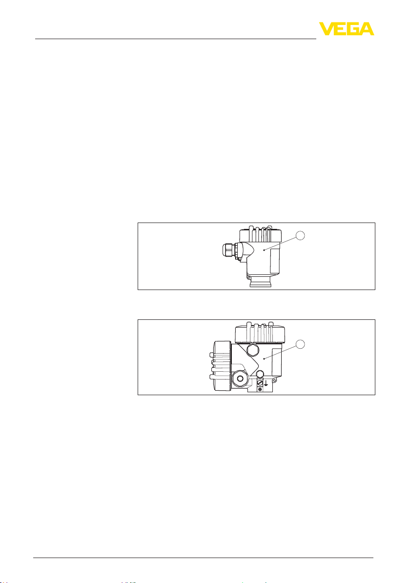
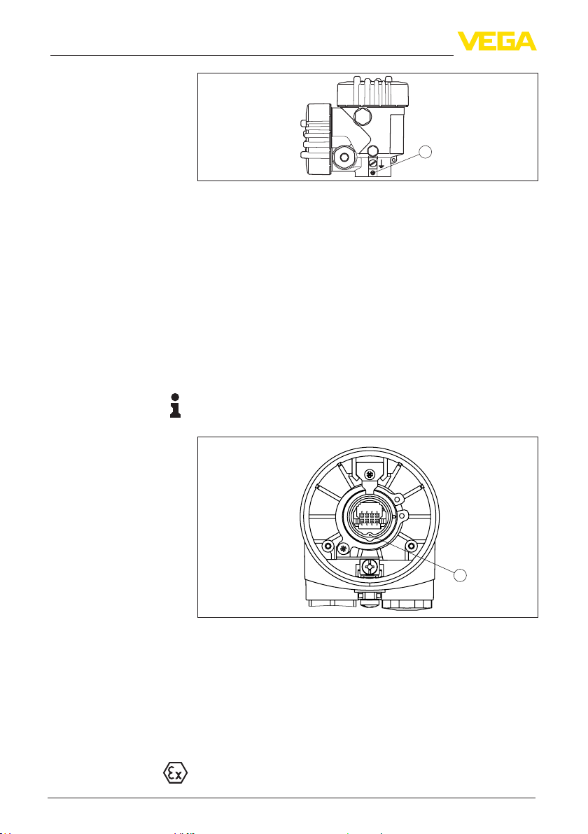
3.1 Conguration.................................................................................................................... 5
3.2 Principle of operation........................................................................................................ 5
3.3 Packaging, transport and storage..................................................................................... 5
4 Mounting................................................................................................................................... 6
4.1 Mounting preparations ..................................................................................................... 6
4.2 Dismounting steps previous process component............................................................. 6
4.3 Mounting steps new process component......................................................................... 8
5 Setup ......................................................................................................................................... 9
5.1 Setup................................................................................................................................ 9
6 Dismount................................................................................................................................. 10
6.1 Dismounting steps.......................................................................................................... 10
6.2 Disposal ......................................................................................................................... 10
7 Supplement ............................................................................................................................ 11
7.1 Technical data ................................................................................................................ 11
Safety instructions for Ex areas
PleasenotetheEx-specicsafetyinformationforinstallationandop-
eration in Ex areas. These safety instructions are part of the operating
instructions and come with the Ex-approved instruments.
Editing status: 2022-08-25

3
1 About this document
Process module • VEGABAR series 80
1013720-EN-220826
1 About this document
1.1 Function
This instruction provides all the information you need for mounting,
connection and setup as well as important instructions for mainte-
nance,faultrectication,theexchangeofpartsandthesafetyofthe
user. Please read this information before putting the instrument into
operation and keep this manual accessible in the immediate vicinity
of the device.
1.2 Target group
This operating instructions manual is directed to trained personnel.
Thecontentsofthismanualmustbemadeavailabletothequalied
personnel and implemented.
1.3 Symbols used
Document ID
This symbol on the front page of this instruction refers to the Docu-
ment ID. By entering the Document ID on www.vega.com you will
reach the document download.
Information, note, tip: This symbol indicates helpful additional infor-
mation and tips for successful work.
Note: This symbol indicates notes to prevent failures, malfunctions,
damage to devices or plants.
Caution: Non-observance of the information marked with this symbol
may result in personal injury.
Warning: Non-observance of the information marked with this symbol
may result in serious or fatal personal injury.
Danger: Non-observance of the information marked with this symbol
results in serious or fatal personal injury.
Ex applications
This symbol indicates special instructions for Ex applications.
• List
The dot set in front indicates a list with no implied sequence.
1 Sequence of actions
Numbers set in front indicate successive steps in a procedure.
Disposal
This symbol indicates special instructions for disposal.

4
2 For your safety
Process module • VEGABAR series 80
1013720-EN-220826
2 For your safety
2.1 Authorised personnel
All operations described in this documentation must be carried out
onlybytrained,qualiedpersonnelauthorisedbytheplantoperator.
During work on and with the device, the required personal protective
equipment must always be worn.
2.2 Appropriate use
Electronics module, emitting electronics, housing or process compo-
nents are replacement components for existing sensors.
2.3 Environmental instructions
Protection of the environment is one of our most important duties.
That is why we have introduced an environment management system
with the goal of continuously improving company environmental pro-
tection.Theenvironmentmanagementsystemiscertiedaccording
to DIN EN ISO 14001.
Pleasehelpusfullthisobligationbyobservingtheenvironmental
instructions in this manual:
• Chapter " Packaging, transport and storage"
• Chapter " Disposal"

5
3 Product description
Process module • VEGABAR series 80
1013720-EN-220826
3 Product description
3.1 Conguration
The scope of delivery encompasses:
• Process module
• Documentation
– This operating instructions manual
3.2 Principle of operation
The process component is suitable as replacement unit for the follow-
ing sensors:
• VEGABAR series 80
3.3 Packaging, transport and storage
Your instrument was protected by packaging during transport. Its
capacity to handle normal loads during transport is assured by a test
based on ISO 4180.
The packaging of standard instruments consists of environment-
friendly, recyclable cardboard. For special versions, PE foam or PE
foil is also used. Dispose of the packaging material via specialised
recycling companies.
Transport must be carried out in due consideration of the notes on the
transport packaging. Nonobservance of these instructions can cause
damage to the device.
The delivery must be checked for completeness and possible transit
damage immediately at receipt. Ascertained transit damage or con-
cealed defects must be appropriately dealt with.
Up to the time of installation, the packages must be left closed and
stored according to the orientation and storage markings on the
outside.
Unless otherwise indicated, the packages must be stored only under
the following conditions:
• Not in the open
• Dry and dust free
• Not exposed to corrosive media
• Protected against solar radiation
• Avoiding mechanical shock and vibration
• Storage and transport temperature see chapter " Supplement -
Technical data - Ambient conditions"
• Relative moisture 20 … 85 %
With instrument weights of more than 18 kg (39.68 lbs) suitable and
approved equipment must be used for lifting and carrying.
Scope of delivery
Application area
Packaging
Transport
Transport inspection
Storage
Storage and transport
temperature
Lifting and carrying

6
4 Mounting
Process module • VEGABAR series 80
1013720-EN-220826
4 Mounting
4.1 Mounting preparations
The following tools are required for dismounting the existing and
mounting the spare process component:
• Magnetic screwdriver Torx size T10 or slot 4
• pliers for locking ring (version axle)
• Screwdriver, slot size 1
• Screwdriver slot 4 (with stainless steel single chamber as well as
stainless steel and aluminium double chamber housing)
4.2 Dismounting steps previous process
component
The electronics module is located in the electronics compartment.
The below illustrations show the respective position of the electronics
compartment in a single or double chamber housing.
1
Fig. 1: Single chamber housing
1 Position of the electronics compartment
1
Fig. 2: Double chamber housing
1 Position of the electronics compartment
Proceed as follows:
1. Switchovoltagesupply
2. Remove the housing lid from the electronics compartment, or
from the terminal compartment of the aluminium double chamber
housing, as the case may be
3. Disconnect the connection cables according to the operating
instructions manual of the respective sensor
4. Loosen the two holding screws with a screwdriver (Torx size T 10
or slot size 4)
Tools
Dismounting the elec-
tronics module

7
4 Mounting
Process module • VEGABAR series 80
1013720-EN-220826
2
555666777888
111222(-)(-)(-)(+)(+)(+)
1
Fig. 3: Loosen the holding screws
1 Electronics module
2 Screws (2 pcs.)
5. Pull the electronics out by holding the opening levers.
Proceed as follows:
1. Loosen the screws of the limit bracket and the locking ring with a
Phillips screwdriver size 1
2
1
3
Fig. 4: Position of the screws and locking ring in the example of the plastic
housing
1 Screw check angle
2 Screw locking ring
3 Retaining ring
2. Open the locking ring with the pliers and remove it
3. Depending on the housing, loosen locking screw on the base
Remove the housing

8
4 Mounting
Process module • VEGABAR series 80
1013720-EN-220826
1
Fig. 5: Double chamber housing
1 Position of the screw
4. Remove the housing
4.3 Mounting steps new process component
1. Place the housing onto the new process component.
2. Depending on the housing, tighten the locking screw on the base
with a screwdriver
3. Insert the locking ring with the pliers
4. Tighten the screws of the limit angle and the locking ring with a
Phillips screwdriver size 1
5. Insert the electronics module carefully.
Information:
Make sure that the plug is in the correct position. The marking notch
must be in position "18.00 h".
1
Fig. 6: Plug position
1 Notch
6. Tighten the two holding screws with a screwdriver (Torx size T 10
or slot size 4)
7. Connect the connection cables according to the operating
instructions manual of the respective sensor
8. Screw the housing lid back on
The process component is exchanged.
As a rule, the exchange of the process component must be docu-
mented internally when used in Ex applications.

9
5 Setup
Process module • VEGABAR series 80
1013720-EN-220826
5 Setup
5.1 Setup
Setup is carried out according to the operating instructions manual of
the respective sensor.

10
6 Dismount
Process module • VEGABAR series 80
1013720-EN-220826
6 Dismount
6.1 Dismounting steps
Take note of chapters " Mounting" and " Connecting to voltage sup-
ply" and carry out the listed steps in reverse order.
6.2 Disposal
Pass the instrument on to a specialised recycling company and do not
use the municipal collecting points.
Remove any batteries in advance, if they can be removed from the
device, and dispose of them separately.
If personal data is stored on the old device to be disposed of, delete it
before disposal.
If you have no way to dispose of the old instrument properly, please
contact us concerning return and disposal.

11
7 Supplement
Process module • VEGABAR series 80
1013720-EN-220826
7 Supplement
7.1 Technical data
Technical data
are stated in the operating instructions manual of the respective sensor.

12
Notes
Process module • VEGABAR series 80
1013720-EN-220826

13
Notes
Process module • VEGABAR series 80
1013720-EN-220826

14
Notes
Process module • VEGABAR series 80
1013720-EN-220826

15
Notes
Process module • VEGABAR series 80
1013720-EN-220826

Printing date:
VEGA Grieshaber KG
Am Hohenstein 113
77761 Schiltach
Germany
1013720-EN-220826
All statements concerning scope of delivery, application, practical use and operat-
ing conditions of the sensors and processing systems correspond to the information
available at the time of printing.
Subject to change without prior notice
© VEGA Grieshaber KG, Schiltach/Germany 2022
Phone +49 7836 50-0
E-mail: [email protected]
www.vega.com
Other manuals for VEGABAR 80 Series
1
Table of contents
Other Vega Control Unit manuals

Vega
Vega VEGADIF 65 User manual

Vega
Vega VEGACAL 60 Series User manual

Vega
Vega VEGAKON 66 User manual

Vega
Vega VEGAPULS 6X User manual

Vega
Vega PLICSMOBILE 80 Series User manual

Vega
Vega VEGADIS 81 User manual

Vega
Vega VEGAKON 61 User manual

Vega
Vega PT30E.SV User manual

Vega
Vega VEGATOR 132 User manual

Vega
Vega VEGACAP 60 Series User manual

Vega
Vega VEGABAR series 80 User manual

Vega
Vega VEGAMIP 60 Series User manual

Vega
Vega VEGADIS 176 Ex Installation instructions

Vega
Vega VEGASWING 66 User manual

Vega
Vega plicscom User manual

Vega
Vega VEGAFLEX 66 User manual

Vega
Vega VEGASON S 62 User manual

Vega
Vega plicscom User manual

Vega
Vega VEGAKON 66 User manual