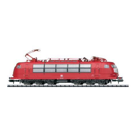
Trix BR 103 User manual

Modell der BR 103 / E 03
16301

2

3
Inhaltsverzeichnis: Seite
Informationen zum Vorbild 4
Sicherheitshinweise 6
Wichtige Hinweise 6
Funktionen 6
Hinweise zum Digitalbetrieb 6
Schaltbare Funktionen 7
Configurations Variablen (CVs) 8
Wartung und Instandhaltung 22
Ersatzteile 30
Table of Contents: Page
Information about the prototype 4
Safety Notes 10
Important Notes 10
Functions 10
Notes on digital operation 10
Controllable Functions 11
Configuration Variables (CVs) 12
Service and maintenance 22
Spare Parts 30
Sommaire : Page
Informations concernant le modèle réelle 5
Remarques importantes sur la sécurité 14
Information importante 14
Fonctionnement 14
Remarques relatives au fonctionement en mode digital 14
Fonctions commutables 15
Variables de configuration (CVs) 16
Entretien et maintien 22
Pièces de rechange 30
Inhoudsopgave: Pagina
Informatie van het voorbeeld 5
Veiligheidsvoorschriften 18
Belangrijke aanwijzing 18
Functies 18
Aanwijzingen voor digitale besturing 18
Schakelbare functies 19
Configuratie variabelen (CV’s) 20
Onderhoud en handhaving 22
Onderdelen 30

4
Informationen zum Vorbild
Als neues Paradepferd von der Deutschen Bundesbahn wurde
1965 bei der internationalen Verkehrsausstellung in Münschen
die neukonstruierte Baureihe E 03 der Öffentlichkeit präsentiert.
Mit einer Höchstgeschwindigkeit vom 200 km/h ermöglichte
diese Reisezuglokomotive eine schnellere Taktverbindung für die
damals vorhandenen TEE-Verbindungen bzw. für das im Aufbau
befindliche Inter-City-Netz.
Der markanteste Unterschied zwischen der Vorserien- und
der Serienausführung der E 03 sind die Anzahl der seitlichen
Lüftungsgitter. Während die spätere Serienversion 10 dieser
Elemente pro Seite besitzt, waren die ersten Modelle nur mit
5 Lüftungsgitter bestückt.
Die Dauerleistung der Vorserienmodelle liegt bei knapp 6.000 kW.
Damit wurden bei Tests Geschwindigkeiten bis über 280 km/h
erreicht.
Achsanordnung Co`Co`
Länge ü. Puffer 19 500 mm
Höchstgeschwindigkeit 200 km/h
Dienstmasse 110 t
Nennleistung 6420 kW (8730 PS)
Baujahr ab 1965
Wheel arrangement C-C
Length over buffers 19,500 mm
Maximum speed 200 km/h / 124 mph
Service weight 110 metric tons
Nominal performance
6,420 kilowatts / 8,730 hp
Built starting in 1965
Information about the prototype
The newly disignet class E 03 was presented in 1965 to the public
at the International Transportation Exhibition in Munich as the
new flagship for the German Federal Railroad. With a maximum
speed of 200 km/h / 125 mph this passenger train locomotive
made it possible to have a faster regularly schedulet service for
the TEE connections that time and for the Inter-City network that
was in the process of being set up.
The most striking difference between the pre-production and the
regular production versions of the E 03 are the number of vents
on the sides. While the later production version has 10 of these
vent grills per side, the first models were only equipped with 5
vent grills per side.
The continuous power of the pre-production models was
6,000 kilowatts or 8,046 horsepower. In tests speeds over
280 km/h / 175 mph were reached with this kind of power.

5
Disposition d‘essieux Co`Co`
Longueur hors tampons 19 500 mm
Vitesse maximale 200 km/h
Poids en ordre de marche 110 t
Puissance nominale 6420 kW (8730 CV)
Construction à partir de 1965
Asindeling CoCo
lengte over de buffers 19 500 mm
maximumsnelheid 200 km/h
dienstgewicht 110 t
nominaalvermogen 6420kW (8730 pk)
bouwjaar vanaf 1965
Informations concernant le modèle réel
Le nouveau cheval de trait de la Deutsche Bundesbahn, la
locomotive série E 03, a été présentée au public en 1965 lors de
la Foire internationale du Transport à Munich. Capable de rouler
à 200 km/h, cette locomotive pour trains de voyageurs permettait
d‘accélérer les cadences des laisons TEE de l‘époque ou du
réseau Inter-City en cours d‘établissement.
La différence la plus marquante entre la présérie et la série
définitive de E 03 résidait dans le nombre de grilles d‘aération
latérales. Les premiers modéles ne possédaient que 5 grilles de
chaque côté tandis que les machnes de la série définitive en
comportaient 10.
La puissance continue des locomotives de présérie s‘élevait à
près de 6 000 kW ce qui a leur a permis d‘atteindre la vitesse de
280 km/h lors de tests.
Informatie over het voorbeeld
Als het nieuwe paradepaard van de Deutsche Bundesbahn, zo
werd in 1965 op de internationale verkeerstentoonstelling in
München, de nieuwe serie E 03 aan het publiek getoond. Met
een maximumsnelheid van 200 km/h maakte deze sneltrein loco-
motief kortere reistijden mogelijk op de toen bestaande
TEE-verbindingen en het in opbouw zijnde intercity-net.
Het markante onderscheid tussen de voorserie en de serie
E 03 locomotieven is het aantal luchtroosters aan de zijkant.
Terwijl de serieuitvoering 10 van deze roosters aan elke zijkant
heeft, waren de eerste modellen met slechts
5 luchtroosters uitgevoerd.
Het continu vermogen van de voorserie kwam op bijna
6 000 kW. Hiermee werd bij het testen een snelheid van meer
dan 280 km/h bereikt.

6
Sicherheitshinweise
• DieLokdarfnurmiteinemdafürbestimmtenBetriebssystem
eingesetzt werden.
• DieLokdarfnichtmitmehralseinerLeistungsquelleversorgt
werden.
• BeachtenSieunbedingtdieSicherheitshinweiseinder
Bedienungsanleitung zu Ihrem Betriebssystem.
• Analog14Volt=,digital22Volt~.
• FürdenkonventionellenBetriebderLokmussdasAnschluss-
gleis entstört werden. Dazu ist das Entstörset 14972 zu ver-
wenden. Für Digitalbetrieb ist das Entstörset nicht geeignet.
• SetzenSiedasModellkeinerdirektenSonneneinstrahlung,
starken Temperaturschwankungen oder hoher Luftfeuchtig-
keit aus.
• DasverwendeteGleisanschlusskabeldarfmaximal
2 Meter lang sein.
• ACHTUNG! Funktionsbedingte scharfe Kanten und Spitzen.
Wichtige Hinweise
• DieBedienungsanleitungunddieVerpackungsindBestand-
teile des Produktes und müssen deshalb aufbewahrt sowie
bei Weitergabe des Produktes mitgegeben werden.
• FürReparaturenoderErsatzteilewendenSiesichbittean
Ihren Trix-Fachhändler.
• GewährleistungundGarantiegemäßderbeiliegendenGaran-
tieurkunde.
• Entsorgung:www.maerklin.com/en/imprint.html
Funktionen
• EingebauteElektronikzumwahlweisenBetriebmit
konventionellem Gleichstrom-Fahrgerät (max. ±12 Volt),
Trix Systems, Trix Selectrix (SX1) und Selectrix 2 (SX2) oder
Digitalsystemen nach NMRA-Norm.
• AutomatischeSystemerkennungzwischenDigital-und
Analog-Betrieb.
• KeineautomatischeSystemerkennungzwischendenDigital-
Systemen.
• Dreilicht-Spitzensignalvorne,zweiroteSchlusslichterhinten,
mit der Fahrtrichtung wechselnd.
• MitKinematikfürKurzkupplungundKupplungsaufnahme
nach NEM.
• DieLokistnichtaufOberleitungsbetriebumschaltbar.
Hinweise zum Digitalbetrieb
• BeimerstenBetriebineinemDigital-System(SX1,SX2oder
DCC) muss der Decoder auf dieses Digital-System eingestellt
werden. Dazu ist der Decoder einmal in diesem Digitalsystem
zu programmieren (z.B. Adresse ändern).
• DerBetriebmitgegenpoligerGleichspannungimBremsab-
schnitt ist mit der werkseitigen Einstellung nicht möglich. Ist
diese Eigenschaft gewünscht, so muss auf den konventio-
nellen Gleichstrombetrieb verzichtet werden
(DCC:CV29/Bit2=0).

7
Schaltbare Funktionen
Spitzensignal fahrtrichtungsabhängig an F0
Maschinenraumbeleuchtung — Funktion 5 F1
Geräusch:Betriebsgeräusch — — — F2
Geräusch:Pfeife — — — F3
ABV, aus — — — F4
Führerstandsbeleuchtung — — — F5
Stirnbeleuchtung Führerstand 1 aus — — — F6
Geräusch:Schaffnerpff — — — F7
Stirnbeleuchtung Führerstand 2 aus — — — F8
Geräusch:Bremsenquietschenaus — — — F9
Geräusch:Bahnhofsansage — — — F10
Rangierlicht doppel A — — — F0 + F6 + F8
Geräusch:Druckluftablassen — — — F12
Geräusch:Bahnhofsansage — — — F13
Geräusch:Bahnhofsansage — — — F14
Geräusch:Lüfter — — — F15
2
7
1
6
STOP
PR
3
8
Sx
5
ON
Lz
4
9
1/2
Central-Control
66800 f0 - f3 f4 - f7
STOP mobile station
15

8
CV Bedeutung Wert DCC ab Werk
1 Adresse 1 – 127 3
2 Minimalgeschwindigkeit 0 – 15 5
3 Anfahrverzögerung 0 – 255 3
4 Bremsverzögerung 0 – 255 5
5 Maximalgeschwindigkeit 0 – 127 100
17 ErweiterteAdresse(obererTeil)(CV29,Bit5=1) 0 – 255 192
18 ErweiterteAdresse(untererTeil)(CV29,Bit5=1) 0 – 255 0
19 Traktionsadresse(0=inaktiv,Wert+128=inverseFahrtrichtung) 0 – 127 0
21 Traktions-Modus; Bit 0 – 7
=
^
F1 – F8 0 – 255 0
22 Traktions-Modus; Bit 0 – 1
=
^
FLf – FLr, Bit 2 – 5
=
^
F9 – F12 0 – 63 0
29
Bit0:UmpolungFahrtrichtung
Bit1:AnzahlFahrstufen14-28/126
Bit2:DCCBetriebmitBremsstrecke
DCC-, Selectrix- und Gleichstrombetrieb
Bit5:Adressumfang17Bit/18Bit
0 – 255
7

9
par Bedeutung Wert SX2 ab Werk
001 Adresse Einer- u. Zehner-Stelle 0 – 99 1
002 Adresse Hunderter- u. Tausender-Stelle 0 – 99 10
011 Anfahrverzögerung 0 – 255 3
012 Bremsverzögerung 0 – 255 5
013 Maximalgeschwindigkeit 0 – 127 100
014 Mindestgeschwindigkeit 0 – 15 5
018 Geschwindigkeit Rangiergang 0 – 127 100
021 Bremsabschnitte; 1 oder 2 0, 1 0
081 Dimmung Licht normal 0 – 31 31
082 Dimmung Licht alternativ 0 – 31 15
WerkseinstellungfürSX1:01-742,erweitert:00-274

10
Functions
• Built-inelectroniccircuitforoptionaloperationwith
a conventional DC train controller (max. ±12 volts),
Trix Systems, Trix Selectrix (SX1), and Selectrix 2 (SX2),
or digital systems adhering to the NMRA standards.
• Automaticsystemrecognitionbetweendigitalandanalog
operation.
• Noautomaticsystemrecognitionbetweenthedigitalsys-
tems.
• Tripleheadlightsinthefront,dualredmarkerlightsinthe
rear, that change over with the direction of travel.
• NEMclosecouplermechanismandcouplerpocket.
• Thelocomotivecannotbeswitchedtooperationfromcatenary.
Notes on digital operation
• Whenoperatinginadigitalsystemforthersttime(SX1,SX2,
or DCC), the decoder must be set to this digital system. To do
this, the decoder must be programmed once in this digital
system(example:changetheaddress).
• Thesettingdoneatthefactorydoesnotpermitoperationwith
opposite polarity DC power in the braking block. If you want
this characteristic, you must do without conventional DC
poweroperation(DCC:CV29/Bit2=0).
Safety Notes
• Thislocomotiveisonlytobeusedwiththeoperatingsystem
it is designed for.
• Thislocomotivemustnotbesuppliedwithpowerfrommore
than one power pack.
• Paycloseattentiontothesafetynotesintheinstructionsfor
your operating system.
• Analog14voltsDC,digital22voltsAC.
• Thefeedertrackmustbeequippedtopreventinterference
with radio and television reception, when the locomotive is to
be run in conventional operation. The 14972 interference sup-
pression set is to be used for this purpose. The interference
suppression set is not suitable for digital operation.
• Donotexposethemodeltodirectsunlight,extremechanges
in temperature, or high humidity.
• Thewireusedforfeederconnectionstothetrackmaybea
maximum of 2 meters / 78 inches long.
• WARNING! Sharp edges and points required for operation.
Important Notes
• Theoperatinginstructionsandthepackagingareacompo-
nent part of the product and must therefore be kept as well as
transferred along with the product to others.
• PleaseseeyourauthorizedTrixdealerforrepairsorspare
parts.
• Thewarrantycardincludedwiththisproductspeciesthe
warranty conditions.
• Disposing:www.maerklin.com/en/imprint.html
11
Controllable Functions
Headlights on F0
Engine room lighting — Function 5 F1
Soundeffect:Operatingsounds — — — F2
Soundeffect:whistleblast — — — F3
ABV, off — — — F4
Engineer‘s cab lighting — — — F5
Headlights at engineer´s cab 1 off — — — F6
Soundeffect:Conductorwhistle — — — F7
Headlights at engineer´s cab 2 off — — — F8
Soundeffect:Squealingbrakesoff — — — F9
Soundeffect:Stationannouncements — — — F10
Double A switching light — — — F0 + F6 + F8
Soundeffect:Lettingoffair — — — F12
Soundeffect:Stationannouncements — — — F13
Soundeffect:Stationannouncements — — — F14
Soundeffect:Blower — — — F15
2
7
1
6
STOP
PR
3
8
Sx
5
ON
Lz
4
9
1/2
Central-Control
66800 f0 - f3 f4 - f7
STOP mobile station
15

12
CV Discription DCC Value Factory
Setting
1 Address 1 – 127 3
2 Minimum Speed 0 – 15 5
3 Acceleration delay 0 – 255 3
4 Braking delay 0 – 255 5
5 Maximum speed 0 – 127 100
17 Extendetaddress(upperpart)(CV29,Bit5=1) 0 – 255 192
18 Extendetaddress(lowerpart)(CV29,Bit5=1) 0 – 255 0
19 Consistaddress(0=inactive,Value+128=inversedirection) 0 – 127 0
21 Motive Power Mode; Bit 0 – 7
=
^
F1 – F8 0 – 255 0
22 Motive Power Mode; Bit 0 – 1
=
^
FLf – FLr, Bit 2 – 5
=
^
F9 – F12 0 – 63 0
29
Bit0:Traveldirectionpolarityreversal
Bit1:numberofspeedlevels14–28/126
Bit2:DCCOperationwithbrakingBlock
DCC-, Selectrix and DC power operation
Bit5:addresssize17Bit/18Bit
0 – 255
7

13
par Discription SX2 Value Factory
Setting
001 Address for one and ten placeholder 0 – 99 1
002 Address for hundred and thousand placeholder 0 – 99 10
011 Acceleration delay 0 – 255 3
012 Braking delay 0 – 255 5
013 Maximum speed 0 – 127 100
014 Minimum speed 0 – 15 5
018 Speed for switching range 0 – 127 100
021 Braking section; 1 or 2 0, 1 0
081 Dimming of lights, normal 0 – 31 31
082 Dimming of lights, alternative 0 – 31 15
FactorysettingforSX1:01-742,advanced:00-774

14
Remarques importantes sur la sécurité
• Lalocomotivenepeutêtreutiliséequ‘aveclesystème
d‘exploitation indiqué.
• Lalocomotivenepeutêtrealimentéeencourantqueparune
seule source de courant.
• Veuillezimpérativementrespecterlesremarquessurla
sécurité décrites dans le mode d’emploi en ce qui concerne
le système d’exploitation.
• Analogique15volts=,digital22volts~.
• Pourl’exploitationdelalocomotiveenmodeconventionnel,
lavoiederaccordementdoitêtredéparasitée.Aceteffet,uti-
liser le set de déparasitage réf. 14972. Le set de déparasitage
ne convient pas pour l’exploitation en mode numérique.
• Nepasexposerlemodèleàunensoleillementdirect,àde
fortes variations de température ou à un taux d‘humidité
important.
• Lecâblederaccordementàlavoieutilisénedoitenaucun
cas dépasser deux mètres.
• ATTENTION! Pointes et bords coupants lors du fonctionne-
ment du produit.
Information importante
• Lanoticed‘utilisationetl’emballagefontpartieintégrantedu
produit;ilsdoiventdoncêtreconservéset,lecaséchéant,
transmis avec le produit.
• Pourtouteréparationouremplacementdepièces,adressez
vous à votre détaillant-spécialiste Trix.
• Garantielégaleetgarantiecontractuelleconformémentau
certificat de garantie ci-joint.
• Elimination:www.maerklin.com/en/imprint.html
Fonctionnement
•
Module électronique intégré pour exploitation au choix avec
régulateur de marche conventionnel c.c. (max. ±12 volts), Trix
Systems, Trix Selectrix (SX1) et Selectrix 2 (SX2) ou systèmes
numériques conformes à la norme NMRA.
• Reconnaissanceautomatiquedusystèmeentreexploitations
numérique et analogique.
• Pasdereconnaissanceautomatiquedusystèmeentreles
systèmes numériques.
• Feuxdesignalisationtriplesàl‘avant,deuxfeuxrouges
de fin de convoi à l‘arrière avec inversion selon sens de
marche.
• AvecboîtiernormaliséNEMàélongationpourattelage
court.
• Lalocomotivenepeutpasêtreexploitéesouscaténaire.
Remarques relatives au fonctionnement en mode digital
• Unepremièreexploitationensystèmenumérique(SX1,SX2
ou DCC) exige un réglage correspondant du décodeur. A
ceteffet,ledécodeurdoitêtreprogramméunefoisdansce
système numérique (modification de l’adresse par ex.).
•
L’exploitation avec courant continu de polarité inverse dans
les sections de freinage n’est pas possible avec le réglage
d’usine. Si cette propriété est désirée, il faut alors renoncer à
l’exploitation conventionnelle en courant continu
(DCC:CV29/Bit2=0).

15
Fonctions commutables
Fanal éclairage activé F0
Éclairage de la salle des machines — Fonction 5 F1
Bruitage:Bruitd’exploitation — — — F2
Bruitage:sifet — — — F3
ABV, désactivé — — — F4
Eclairage de la cabine de conduite — — — F5
Fanal de la cabine de conduite 1 éteint — — — F6
Bruitage:SifetContrôleur — — — F7
Fanal de la cabine de conduite 2 éteint — — — F8
Bruitage:Grincementdefreinsdésactivé — — — F9
Bruitage:Annonceengare — — — F10
Feu de manœuvre double A — — — F0 + F6 + F8
Bruitage:Échappementdel‘aircomprimé — — — F12
Bruitage:Annonceengare — — — F13
Bruitage:Annonceengare — — — F14
Bruitage:ventilateur — — — F15
2
7
1
6
STOP
PR
3
8
Sx
5
ON
Lz
4
9
1/2
Central-Control
66800 f0 - f3 f4 - f7
STOP mobile station
15

16
CV Signification Valeur DCC Valeur Parm. Usine
1 Adresse 1 – 127 3
2 Vitesse min 0 – 15 5
3 Temporisation d‘accélération 0 – 255 3
4 Temporisation de freinage 0 – 255 5
5 Vitesse maximale 0 – 127 100
17 Adresseétendue(partiesupérieure)(CV29,Bit5=1) 0 – 255 192
18 Adresseétendue(partieinférieure)(CV29,Bit5=1) 0 – 255 0
19 Adressepourlatraction(0=inactif,Valeur+128=directioninverse) 0 – 127 0
21 Mode traction, bit 0 à 7
=
^
F1 à F8 0 – 255 0
22 Mode traction; bit 0 à 1
=
^
FLf à FLr, Bit 2 à 5
=
^
F9 à F12 0 – 63 0
29
Bit0:inversiondepolarité,sensdemarche
Bit1:Nombredecransdemarche14–28/126
Bit2:ExploitationDCCaveczonedefreinage.
DCC-, Selectrix et courant continu
Bit5:tailled‘adresse7Bits/14Bits
0 – 255
7

17
par Signification Valeur SX2 Valeur Parm. Usine
001 Adresse unités et décimales 0 – 99 1
002 Adresse centaines et milliers 0 – 99 10
011 Temporisation d’accélération 0 – 255 3
012 Temporisation de freinage 0 – 255 5
013 Vitesse maximale 0 – 127 100
014 Vitesse minimale 0 – 15 5
018 Vitesse de manoeuvre 0 – 127 100
021 Sections de freinage, 1 ou 2 0, 1 0
081 Variation lumière normale 0 – 31 31
082 Variation lumière alternative 0 – 31 15
Paramètresd’usinepourSX1:01à742,étendus:00à774

18
Veiligheidsvoorschriften
• Delocmagalleenmeteendaarvoorbestemdbedrijfssysteem
gebruikt worden.
• Delocmagnietvanuitmeerdaneenstroomvoorziening
gelijktijdig gevoed worden.
• Leesookaandachtigdeveiligheidsvoorschrifteninde
gebruiksaanwijzing van uw bedrijfssysteem.
• Analoog15Volt=,digitaal22Volt~.
• Voorhetconventionelebedrijfmetdelocdientdeaansluitrail
te worden ontstoort. Hiervoor dient men de ontstoor-set 14972
te gebruiken. Voor het digitale bedrijf is deze ontstoor-set niet
geschikt.
• Stelhetmodelnietblootaanindirectezonnestraling,sterke
temperatuurwisselingen of hoge luchtvochtigheid.
• Degebruikteaansluitkabelmagmaximaal2meterlangzijn.
• OPGEPAST! Functionele scherpe kanten en punten.
Belangrijke aanwijzing
• Degebruiksaanwijzingendeverpakkingzijneenbestanddeel
van het product en dienen derhalve bewaard en meegeleverd
te worden bij het doorgeven van het product.
• VoorreparatiesenonderdelenkuntzichtotUwTrixhandelaar
wenden.
• Vrijwaringengarantieovereenkomstighetbijgevoegde
garantiebewijs.
• Afdanken:www.maerklin.com/en/imprint.html
Functies
• Ingebouwdeelektronicanaarkeuzetoepasbaarmetcon-
ventionele gelijkstroomregelaar (max. ±12 volt), Trix Systems,
Trix Selectrix (SX1) en Selectrix 2 (SX2) of digitaalsystemen
volgens NMRA-norm.
• Automatischesysteemherkenningtussendigitaal-enana-
loogbedrijf.
• Geenautomatischeherkenningtussendedigitalesystemen.
• Drie-lichtsfrontseinvoor,tweerodesluitseinenachter,
wisselend met de rijrichting.
• Metkortkoppelingsmechaniekenkoppelingsopnameschacht
volgens NEM.
• Delockannietomgeschakeldwordenopbovenleiding.
Aanwijzingen voor digitale besturing
• Bijhetvoorheteerstinbedrijfnemenineendigitaalsysteem
(Sx1, Sx2 of DCC) moet de decoder ingesteld op dit digitale
systeem. Hiervoor moet de decoder éénmaal in dat digitale
systeem geprogrammeerd worden (bijv. het adres wijzigen).
• Hetbedrijfmettegengepooldegelijkspanningindeafrem-
sectie is met de fabrieksinstelling niet mogelijk. Indien deze
eigenschap wenselijk is, dan moet worden afgezien van het
conventioneel gelijkstroombedrijf
(DCC:CV29/Bit2=0).

19
Schakelbare functies
Frontsein aan F0
Verlichting machineruimte — Functie 5 F1
Geluid:bedrijfsgeluiden — — — F2
Geluid:uit — — — F3
ABV, uit — — — F4
Cabineverlichting — — — F5
Frontverlichting Cabine 1 uit — — — F6
Geluid:conducteuruit — — — F7
Frontverlichting Cabine 2 uit — — — F8
Geluid:piependeremmenuit — — — F9
Geluid:stationsomroep — — — F10
Rangeerlicht dubbel A — — — F0 + F6 + F8
Geluid:persluchtafblazen — — — F12
Geluid:stationsomroep — — — F13
Geluid:stationsomroep — — — F14
Geluid:ventilator — — — F15
2
7
1
6
STOP
PR
3
8
Sx
5
ON
Lz
4
9
1/2
Central-Control
66800 f0 - f3 f4 - f7
STOP mobile station
15

20
CV Betekenis Waarde DCC Af fabriek
1 adres 1 – 127 3
2 Minimalgeschwindigkeit 0 – 15 5
3 optrekvertraging 0 – 255 3
4 afremvertraging 0 – 255 5
5 maximumsnelheid 0 – 127 100
17 uitgebreldadres(bovenstegedeelte)(CV29,Bit5=1) 0 – 255 192
18 uitgebreldadres(onderstegedeelte)(CV29,Bit5=1) 0 – 255 0
19 Adresvoortractie(0=inactief,Waarde+128=omgekeerderichting) 0 – 127 0
21 Tractie-modus ; bit 0 - 7
=
^
F1 - F8 0 – 255 0
22 Tractie-modus ; bit 0 - 1
=
^
FLf - FLr, bit 2 - 5
=
^
F9 - F12 0 – 63 0
29
Bit0:ompolingrijrichting
Bit1:aantalrijstappen14–28/126
Bit2:DCC-bedrijfmetafremtraject
DCC-, Selectrix- en gelijkstroombedrijf
Bit5:adresbereik17Bit/18Bit
0 – 255
7
Other manuals for BR 103
1
This manual suits for next models
2
Table of contents
Languages:
Other Trix Toy manuals

Trix
Trix Minitrix 66301 User manual

Trix
Trix 11206 User manual

Trix
Trix H0 041 Series User manual

Trix
Trix minitrix BR 648 User manual

Trix
Trix E-Lok Ae 8/14 User manual

Trix
Trix Triebzuges ET 87 User manual

Trix
Trix BR 45 User manual

Trix
Trix minitrix VT 75 Operating instructions

Trix
Trix G8.1 User manual

Trix
Trix BR 212 User manual