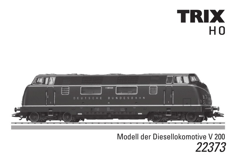
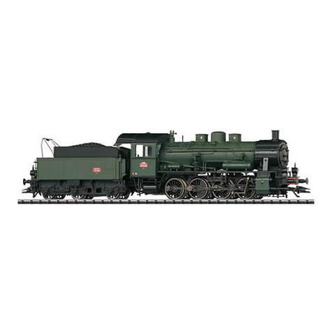
Trix BR 39 User manual

Modell der Dampflok BR 39
22393

2
Inhaltsverzeichnis: Seite
Informationen zum Vorbild 4
Hinweise zur Inbetriebnahme 6
Sicherheitshinweise 8
Wichtige Hinweise 8
Funktionen 8
Schaltbare Funktionen 9
Parameter / Register 10
Ergänzendes Zubehör 32
Wartung und Instandhaltung 35
Ersatzteile 41
Table of Contents: Page
Information about the prototype 4
Notes about using this model for the first time 6
Safety Notes 11
Important Notes 11
Functions 11
Controllable Functions 12
Parameter / Register 13
Completing accessories 32
Service and maintenance 35
Spare Parts 41
Sommaire : Page
Informations concernant la locomotive réelle 5
Indications relatives à la mise en service 6
Remarques importantes sur la sécurité 14
Information importante 14
Fonctionnement 14
Fonctions commutables 15
Paramètre / Registre 16
Accessoires complémentaires 32
Entretien et maintien 35
Pièces de rechange 41
Inhoudsopgave: Pagina
Informatie van het voorbeeld 5
Opmerking voor de ingebruikname 6
Veiligheidsvoorschriften 17
Belangrijke aanwijzing 17
Functies 17
Schakelbare functies 18
Parameter / Register 19
Aanvullende toebehoren 32
Onderhoud en handhaving 35
Onderdelen 41

3
Indice de contenido: Página
Notas para la puesta en servicio 6
Aviso de seguridad 20
Notas importantes 20
Funciones 20
Funciones posibles 21
Parámetro / Registro 22
Accesorios complementarios 32
El mantenimiento 35
Recambios 41
Indice del contenuto: Pagina
Avvertenza per la messa in esercizio 6
Avvertenze per la sicurezza 23
Avvertenze importanti 23
Funzioni 23
Funzioni commutabili 24
Parametro / Registro 25
Accessori complementari 32
Manutenzione ed assistere 35
Pezzi di ricambio 41
Innehållsförteckning: Sida
Anvisningar för körning med modellen 6
Säkerhetsanvisningar 26
Viktig information 26
Funktioner 26
Kopplingsbara funktioner 27
Parameter / Register 28
Ytterligare tillbehör 32
Underhåll och reparation 35
Reservdelar 41
Indholdsfortegnelse: Side
Henvisninger til ibrugtagning 6
Vink om sikkerhed 29
Vigtige bemærkninger 29
Funktioner 29
Styrbare funktioner 30
Parameter / Register 31
Ekstra tilbehør 32
Service og reparation 35
Reservedele 41

4
Informationen zum Vorbild
BR P10 / BR 39 – Starke Lok im Mittelgebirge.
1919 begannen die Entwicklungen bei der Firma Borsig in Berlin
für eine Schlepptender-Personenzuglokomotive mit der Achsfol-
ge 1’D1’ „Mikado“. Ihr Aufgabenbereich war vor allem die Be-
wältigung des schweren Schnellzugbetriebes im Mittelgebirge.
Am häufigsten war sie auf der Main-Weser-Bahn, der Eifelbahn,
der Schwarzwaldbahn, der Gäubahn und in Sachsen anzutreffen.
Zwischen 1922 und 1927 verließen insgesamt 260 Exemplare der
vierfachgekuppelten Maschinen die Werkshallen, die die Deut-
sche Reichsbahn Gesellschaft (DRG) als Baureihe 39 einordnete
und nach dem 2. Weltkrieg
in beiden deutschen Staaten unver-
zichtbar war. Die 22.890 mm
langen und 100,4 t schweren Maschi-
nen erreichten mit ihrem Dreizylinder-Triebwerk eine Höchst-
geschwindigkeit von 110 km/h und eine induzierte Leistung von
1.620 PSi. Bei der Deutschen Bundesbahn erhielten die meisten
Lokomotiven Witte Windleitbleche und den Tender 2’2’ T 34, die
den Tender pr2’2’ T 31,5 ersetzten. Ihren Einsatz bei der DB be-
endete die BR 39 in Stuttgart, wo 1967 die letzten drei Exemplare
aus dem aktiven Dienst schieden. Für die Deutsche Reichsbahn
der DDR waren die bei ihr verbliebenen 85 Lokomotiven unent-
behrlich und sie wurden in das Rekonstruktionsprogramm mit
einbezogen und danach als Baureihe 22 eingereiht.
Die 39 230 der Deutschen Bundesbahn wurde der Nachwelt er-
halten und man kann die beeindruckende Lok derzeit im Deut-
schen Dampflok Museum in Neuenmarkt in Oberfranken, am Fuß
der berühmt-berüchtigten „Schiefen Ebene“ besichtigen.
Information about the Prototype
The Class P10 / BR 39 – A Powerful Locomotive in the
Central Mountains.
In 1919, development began at the firm of Borsig in Berlin for a
passenger locomotive with a 2-8-2 “Mikado” wheel arrangement.
Its job was chiefly to master heavy express train operation in the
Mittelgebirge region. It could often be seen on the Main-Weser
line, the Eifel line, the Schwarzwald or Black Forest line, the Gäu
line, and in Saxony. Between 1922 and 1927, a total of 260 units
of this locomotive with four driving axles left the builder‘s halls
that the German State Railroad Company (DRG) designated as
the class 39 and that were indispensable after World War II in
both of the German states. These locomotives measured 22,890
mm / 75 feet 1-3/16 inches long and weighed 100.4 metric tons.
They reached a maximum speed of 110 km/h / 68 mph with their
three-cylinder running gear and had an indexed performance of
1,620 horsepower.
On the German Federal Railroad most of these locomotives were
equipped with Witte smoke deflectors and the type 2’2’ T 34 ten-
der, which replaced the type pr2’2’ T 31,5 tender. The DB retired
the class 39 in Stuttgart, where the last three units disappeared
from service in 1967. For the German State Railroad of East Ger-
many the 85 locomotives remaining there were indispensable and
they were included in the rebuilding program there and after-
wards designated as the class 22.
Road number 39 230 on the German Federal Railroad was preser-
ved and you can currently see this impressive locomotive in the
German Steam Locomotive Museum in Neuenmarkt in Upper Fran-
conia at the foot of the famous/infamous “Schiefe Ebene” grade.

5
Informations concernant la locomotive réelle
BR P10 / BR 39 – Locomotive puissante en moyenne montagne.
En 1919, la firme berlinoise Borsig entama la conception d’une
locomotive à tender séparé pour trains voyageurs avec la dis-
position d’essieux 141 «Mikado». Cette machine devait avant
tout être capable d’assumer le trafic de trains rapides lourds
en moyenne montagne. On la rencontrait le plus souvent sur
le «Main-Weser-Bahn», le «Eifelbahn» (la ligne de l’Eifel), le
«Schwarzwaldbahn» (chemin de fer de la Forêt Noire), le Gäu-
bahn ainsi qu’en Saxe. Entre 1922 et 1927, 260 unités au total
de ces machines à quatre essieux couplés quittèrent les halles
d’usines et furent immatriculées par la Deutsche Reichsbahn
Gesellschaft (DRG) dans la série 39 ; après la seconde guerre
mondiale, ces locos étaient indispensables dans les deux Etats
allemands. Grâce à leurs 3 cylindres, ces machines de 22890 mm
de long et de 100,4 tonnes atteignaient une vitesse maximale de
110 km/h et une puissance induite de 1620 ch.
A la Deutsche Bundesbahn, la plupart des locomotives furent
équipées d’écrans pare-fumée Witte et du tender 2’2’ T 34
qui remplaçait le tender pr2’2’ T 31,5. Le service à la DB de la
BR 39 se termina à Stuttgart, où les trois dernières unités furent
réformées en 1967. La Deutsche Reichsbahn de la RDA, quant à
elle, ne pouvait se passer des 85 locomotives qui lui étaient res-
tées ; celles-ci furent donc intégrées au programme de recons-
truction, puis immatriculées dans la série 22.
La 39 230 de la Deutsche Bundesbahn, qui fut conservée pour la
postérité, est actuellement exposée au Musée allemand de la Lo-
comotive à vapeur à Neuenmarkt (Haute Franconie), au pied de la
tristement célèbre ligne ferroviaire du «Schiefe Ebene» (Ludwig-
Süd-Nord-Bahn entre Bamberg et Hof/Saale).
Informatie van het voorbeeld
BR P10/BR 39 – Sterke loc in het middelgebergte.
In 1919 begonnen de ontwikkelingen bij de firma Borsig in Ber-
lijn voor een reizigerstreinlocomotief met getrokken tender met
de asindeling 1’D1’ ”Mikado”. Haar takenpakket was vooral
het trekken van de zware sneltreinen in het middelgebergte.
Het meest was ze op de Main-Weser-Bahn, de Eifelbahn, de
Schwarzwaldbahn, de Gäubahn en in Sachsen aan te treffen.
Tussen 1922 en 1927 verlieten in totaal 260 exemplaren van
de viervoudig gekoppelde machines de fabriekshallen, die de
Deutsche Reichsbahn Gesellschaft (DRG) als serie 39 in het
bestand opnam en na de Tweede Wereldoorlog kon ze in bei-
de Duitse staten niet gemist worden. De 22.890 mm lange en
100,4 t zware machines bereikten met hun driecilinder drijfwerk
een maximumsnelheid van 110 km/h en een geïndiceerd vermo-
gen van 1.620 pki.
Bij de Deutsche Bundesbahn kregen de meeste locomotie-
ven Witte-windleibladen en de tender 2’2’ T 34, die de tender
pr2’2’ T 31,5 vervingen. De BR 39 beëindigde hun inzet bij de DB
in Stuttgart, waar in 1967 de laatste drie exemplaren uit de actie-
ve dienst verdwenen. Voor de Deutsche Reichsbahn in de DDR
waren de aldaar overgebleven 85 locomotieven onontbeerlijk en
ze werden in het reconstructieprogramma opgenomen en daarna
als serie 22 in het bestand opgenomen.
De 39 230 van de Deutsche Bundesbahn werd voor het nageslacht
behouden en men kan de indrukwekkende loc momenteel in het
Duitse stoomlocmuseum in Neumarkt in Oberfranken, aan de voet
van de beroemde en gevreesde “Schiefe Ebene” bezichtigen.
6
Übergangsgleis / Steigung und Bogenanfang
Transfer rail / gradient and start of bend
Rail de transition / montée et début de courbe
Overgangsrail / Steiging en boogbegin
Vía de transición / cuesta e inicio de la curva
Binario di raccordo / pendenza ed inizio della curva
Övergångsräls / stigning och början av kurva
Overgangsspor / stigning og kurvestart
Radius > 500 mm

7
Kurzkupplung zwischen Lok und Tender verstellbar
Close coupling between locomotive and tender is adjustable
Attelage court réglable entre locomotive et tender
Kortkoppeling tussen loc en tender is verstelbaar
El enganche corto ajustable entre locomotora y ténder
Aggancio corto regolabile tra locomotiva e tender
Kortkopplet mellan lok och tender kan regleras
Kortkobling mellem lok og tender indstillelig
Radius > 500 mm

8
Sicherheitshinweise
• DieLokdarfnurmiteinemdafürbestimmtenBetriebssystem
eingesetzt werden.
• Analogmax.15Volt=,digitalmax.22Volt~.
• DieLokdarfnurausalseinerLeistungsquelleversorgt
werden.
• BeachtenSieunbedingtdieSicherheitshinweiseinder
Bedienungsanleitung zu Ihrem Betriebssystem.
• FürdenkonventionellenBetriebderLokmussdasAnschluss-
gleis entstört werden. Dazu ist das Entstörset 611 655 zu ver-
wenden. Für Digitalbetrieb ist das Entstörset nicht geeignet.
• ACHTUNG! Funktionsbedingte scharfe Kanten und Spitzen.
• SetzenSiedasModellkeinerdirektenSonneneinstrahlung,
starken Temperaturschwankungen oder hoher Luftfeuchtig-
keit aus.
Wichtige Hinweise
• DieBedienungsanleitungunddieVerpackungsindBestand-
teil des Produktes und müssen deshalb aufbewahrt sowie bei
Weitergabe des Produktes mitgegeben werden.
• FürReparaturenoderErsatzteilewendenSiesichbittean
Ihren Trix-Fachhändler.
• http://www.maerklin.com/en/imprint.html
Funktionen
• EingebauteElektronikzumwahlweisenBetriebmitkonventio-
nellem Gleichstrom-Fahrgerät, Trix Systems oder Digitalsyste-
men nach NMRA-Norm.
• AutomatischeSystemerkennungzwischenDigital-und
Analog-Betrieb.
• DervolleFunktionsumfangistnurunterTrixSystemsund
unter DCC verfügbar.
• Eingebaute,fahrtrichtungsabhängigeStirnbeleuchtung.
Im Digitalbetrieb schaltbar.
• BefahrbarerMindestradius360mm.
Hinweise zum Digitalbetrieb
• DiegenaueVorgehensweisezumEinstellenderdiversen
Parameter entnehmen Sie bitte der Bedienungsanleitung
Ihrer Mehrzug-Zentrale.
• DieabWerkeingestelltenWertesindsogewählt,dass
bestmöglichstes Fahrverhalten gewährleistet ist.
• DerBetriebmitgegenpoligerGleichspannungimBremsab-
schnitt ist mit der werkseitigen Einstellung nicht möglich. Ist
diese Eigenschaft gewünscht, so muss auf den konventio-
nellenGleichstrombetriebverzichtetwerden(CV29/Bit2=0).
Jegliche Garantie-, Gewährleistungs- und Schadensersatzansprüche
sind ausgeschlossen, wenn in Trix-Produkten nicht von Trix freigegebene
Fremdteile eingebaut werden und/oder Trix-Produkte umgebaut werden
und die eingebauten Fremdteile bzw. der Umbau für sodann aufgetretene
Mängel und/oder Schäden ursächlich war. Die Darlegungs- und Beweislast
dafür, dass der Einbau von Fremdteilen oder der Umbau in bzw. von Trix-
Produkten für aufgetretene Mängel und/oder Schäden nicht ursächlich
war, trägt die für den Ein- und/oder Umbau verantwortliche Person und/
oder Firma bzw. der Kunde.

9
Schaltbare Funktionen
Stirnbeleuchtung an Licht-Taste Funktion f0
Rauchgenerator 1an — Funktion 1 Funktion f1
Betriebsgeräusch — — Funktion 2 Funktion f2
Geräusch:Lokpfeife — — Funktion 3 Funktion f3
ABV, aus — — Funktion 4 Funktion f4
Geräusch:Luftpumpe — — Funktion 5 Funktion f5
Geräusch:Rangierpff — — Funktion 7 Funktion f7
Geräusch:Dampfablassen — — Funktion 8 Funktion f8
Geräusch:Bremsenquietschenaus — — — Funktion f9
Geräusch:Kohleschaufeln — — — Funktion f10
Geräusch:Schüttelrost — — — Funktion f11
1 Gehört nicht zum Lieferumfang

10
CV Bedeutung Wert DCC ab Werk
1 Adresse 1 - 127 3
2 PoM Minimalgeschwindigkeit 0 - 255 18
3 PoM Anfahrverzögerung 0 - 255 5
4 PoM Bremsverzögerung 0 - 255 4
5 PoM Maximalgeschwindigkeit 0 - 255 212
8 Werkreset/Herstellerkennung 8 131
13 PoM Funktionen F1 - F8 im Analogbetrieb 0 - 255 1
14 PoM Funktionen F9 - F15 und Licht im Analogbetrieb 0 - 255 1
17 Erweiterte Adresse (oberer Teil) CV29,Bit5=1 192
18 Erweiterte Adresse (unterer Teil) CV29,Bit5=1 128
19 Traktionsadresse 0 - 255 0
21 PoM Funktionen F1 - F8 bei Traktion 0 - 255 0
22 PoM Funktionen F9 - F15 und Licht bei Traktion 0 - 255 0
29
Bit0:UmpolungFahrtrichtung
Bit1:AnzahlFahrstufen14oder28/128
Bit2:DCCBetriebmitBremsstrecke
(kein Analogbetrieb möglich)
Bit5:Adressumfang7Bit/14Bit
0 / 1
0 / 2
0 / 4
0 / 32
***
0, 1, 2, 3, 4, 5, 6, 7,
32, 34, 35, 36, 37,
38, 39
6
63 Lautstärke 0 - 255 210
PoM Program on the Main; muss vom Steuergerät unterstützt werden
*** Die Werte der gewünschten Einstellungen sind zu addieren!

11
Functions
• Built-inelectroniccircuitforoperationwithaconventional
DC power pack, Trix Systems or NMRA DCC digital systems.
• Automaticsystemrecognitionbetweendigitalandanalog
operation.
• ThefullrangeoffunctionsisonlyavailableunderTrixSys-
tems and under DCC.
• Built-inheadlightsthatchangeoverwiththedirectionof
travel. They can be turned on and off in digital operation.
• Minimumradiusforoperationis360mm/14-3/16“.
Notes on digital operation
• Theoperatinginstructionsforyourcentralunitwillgiveyou
exact procedures for setting the different parameters.
• Thevaluessetatthefactorywereselectedtoguaranteethe
best possible running characteristics.
• Thesettingdoneatthefactorydoesnotpermitoperationwith
opposite polarity DC power in the braking block. If you want
this characteristic, you must do without conventional DC
poweroperation(CV29/Bit2=0).
No warranty or damage claims shall be accepted in those cases where
parts neither manufactured nor approved by Trix have been installed in
Trix products or where Trix products have been converted in such a way
that the non-Trix parts or the conversion were causal to the defects and/
or damage arising. The burden of presenting evidence and the burden of
proof thereof, that the installation of non-Trix parts or the conversion in or
of Trix products was not causal to the defects and/or damage arising, is
borne by the person and/or company responsible for the installation and/or
conversion, or by the customer.
Safety Notes
• Thislocomotiveisonlytobeusedwiththeoperatingsystem
it is designed for.
• Analogmax.15voltsDC,digitalmax.22voltsAC.
• Thislocomotivemustneverbesuppliedwithpowerform
more than one power pack.
• Pleasemakenoteofthesafetynotesintheinstructionsfor
your operating system.
• Thefeedertrackmustbeequippedtopreventinterference
with radio and television reception, when the locomotive is
to be run in conventional operation. The 611 655 interference
suppression set is to be used for this purpose. The interfe-
rence suppression set is not suitable for digital operation.
• WARNING! Sharp edges and points required for operation.
• Donotexposethemodeltodirectsunlight,extremechanges
in temperature, or high humidity.
Important Notes
• Theoperatinginstructionsandthepackagingareacompo-
nent part of the product and must therefore be kept as well as
transferred along with the product to others.
• PleaseseeyourauthorizedTrixdealerforrepairsorspare
parts.
• http://www.maerklin.com/en/imprint.html

12
Controllable Functions
Headlights on Headlight button Function f0
Smoke generator 1on — Function 1 Function f1
Operating sounds — — Function 2 Function f2
Soundeffect:Locomotivewhistle — — Function 3 Function f3
ABV, off — — Function 4 Function f4
Soundeffect:Airpump — — Function 5 Function f5
Soundeffect:Switchingwhistle — — Function 7 Function f7
Soundeffect:Blowingoffsteam — — Function 8 Function f8
Soundeffect:Squealingbrakesoff — — — Function f9
Soundeffect:Coalbeingshoveled — — — Function f10
Soundeffect:Rockergrate — — — Function f11
1 Not included in delivery scope.

13
PoM Program on the Main; must be supported by the controller
*** The values for the desired settings must be added.
CV Discription DCC Value Factory-Set
1 Address 1 - 127 3
2 PoM Minimum Speed 0 - 255 18
3 PoM Acceleration delay 0 - 255 5
4 PoM Braking delay 0 - 255 4
5 PoM Maximum speed 0 - 255 212
8 Factory Reset / Manufacturer Recognition 8 131
13 PoM Functions F1 - F8 in analog operation 0 - 255 1
14 PoM Functions F9 - F15 and lights in analog operation 0 - 255 1
17 Extended address (upper part) CV29,Bit5=1 192
18 Extended address (lower part) CV29,Bit5=1 128
19 Multiple Unit Address 0 - 255 0
21 PoM Functions F1 - F8 on Multiple Unit 0 - 255 0
22 PoM Functions F9 - F15 and lights on Multiple Unit 0 - 255 0
29
Bit0:Reversingdirection
Bit1:Numberofspeedlevels14or28/128
Bit2:DCCoperationwithbrakingarea
(no analog operation possible)
Bit5:Addresslength7Bit/14Bit
0 / 1
0 / 2
0 / 4
0 / 32
***
0, 1, 2, 3, 4, 5, 6, 7,
32, 34, 35, 36, 37,
38, 39
6
63 Volume 0 - 255 210

14
Remarques importantes sur la sécurité
• Lalocomotivenepeutêtreutiliséequ‘aveclesystème
d‘exploitation indiqué.
• Analogiquemax.15Volt=,numériquemax.22Volt~.
• Lalocomotivenepeutpasêtrealimentéeélectriquementpar
plus d‘une source de courant à la fois.
• Ilestimpératifdetenircomptedesremarquessurla
sécurité décrites dans le mode d‘emploi de votre système
d‘exploitation.
•
Pour l’exploitation de la locomotive en mode conventionnel, la
voie de raccordement doit être déparasitée. A cet effet, utili-
ser le set de déparasitage réf. 611 655. Le set de déparasitage
ne convient pas pour l’exploitation en mode numérique.
•
ATTENTION! Pointes et bords coupants lors du fonctionnement
du produit.
• Nepasexposerlemodèleàunensoleillementdirect,àde
fortes variations de température ou à un taux d‘humidité
important.
Information importante
• Lanoticed‘utilisationetl’emballagefontpartieintégrantedu
produit ; ils doivent donc être conservés et, le cas échéant,
transmis avec le produit.
• Pourtouteréparationouremplacementdepièces,adressez
vous à votre détaillant-spécialiste Trix.
• http://www.maerklin.com/en/imprint.html
Fonctionnement
• Electroniqueintégréepourexploitationauchoixavectransforma-
teur-régulateur conventionnel délivrant du courant continu (max.
±12 volts), avec Trix Systems ou avec des systèmes de conduite
digitale conformes aux normes NMRA.
• Reconnaissanceautomatiquedusystèmeentreexploitations
numérique et analogique.
• L’intégralitédesfonctionsestdisponibleuniquementen
exploitation Trix Systems et DCC.
• Feuxdesignalisations‘inversantselonlesensdemarche;
feux commutables en exploitation digital.
• Rayonminimald’inscriptionencourbe360mm.
Remarques relatives au fonctionnement en mode digital
• Encequiconcernelaprocédurederéglagedesdivers
paramètres, veuillez vous référer au mode d‘emploi de votre
centrale de commande multitrain.
• Lesvaleursparamétréesd’usinesontchoisiesdemanièreà
garantir le meilleur comportement de roulement possible.
• L’exploitationaveccourantcontinudepolaritéinversedans
les sections de freinage n’est pas possible avec le réglage
d’usine. Si cette propriété est désirée, il faut alors renoncer à
l’exploitation conventionnelle en courant continu (CV 29/Bit 2
=0).
Tout recours à une garantie commerciale ou contractuelle ou à une demande
de dommages-intérêt est exclu si des pièces non autorisées par Trix sont
intégrées dans les produits Trix et/ou si les produits Trix sont transformés et
si les pièces d’autres fabricants montées ou la transformation constituent la
cause des défauts et/ou dommages apparus. C’est à la personne et/ou la so-
ciété responsable du montage/de la transformation ou au client qu’incombe
la charge de prouver que le montage des pièces d’autres fabricants sur des
produits Trix ou la transformation des produits Trix n’est pas à l’origine des
défauts et ou dommages apparus.

15
Fonctions commutables
Fanal activé Touche éclairage Fonction f0
Générateur de fumée 1activé — Fonction 1 Fonction f1
Bruit d’exploitation — — Fonction 2 Fonction f2
Bruitage:Siffletlocomotive — — Fonction 3 Fonction f3
ABV, désactivé — — Fonction 4 Fonction f4
Bruitage:Compresseur — — Fonction 5 Fonction f5
Bruitage:Siffletpourmanœuvre — — Fonction 7 Fonction f7
Bruitage:Échappementdelavapeur — — Fonction 8 Fonction f8
Bruitage:Grincementdefreinsdésactivé — — — Fonction f9
Bruitage:Pelletageducharbon — — — Fonction f10
Bruitage:Grilleàsecousses — — — Fonction f11
1 Ne fait pas partie de la fourniture.

16
PoM Program on the Main; doit être pris en charge par l’appareil de commande
*** Les valeurs des réglages désirés sont à additioner.
CV Affection DCC Valeur Parm. Usine
1 Adresse 1 - 127 3
2 PoM Vitesse min 0 - 255 18
3 PoM Temporisation d‘accélération 0 - 255 5
4 PoM Temporisation de freinage 0 - 255 4
5 PoM Vitesse maximale 0 - 255 212
8 Réinitialisation d’usine/identification du fabricant 8 131
13 PoM Fonctions F1 - F8 en mode analog 0 - 255 1
14 PoM Fonctions F9 - F15 et éclairage en mode analog 0 - 255 1
17 Adresse étendue (partie supérieure) CV29,Bit5=1 192
18 Adresse étendue (partie inférieure) CV29,Bit5=1 128
19 Adresse traction 0 - 255 0
21 PoM Fonctions F1 - F8 pour traction 0 - 255 0
22 PoM Fonctions F9 - F15 et éclairage traction 0 - 255 0
29
Bit0:Inv.polaritéSensdemarche
Bit1:Nombredecransdemarche14ou28/128
Bit2:
Mode DCC avec dist. de freinage (mode analog impossible)
Bit5:Capacitéd’adresses7Bit/14Bit
0 / 1
0 / 2
0 / 4
0 / 32
***
0, 1, 2, 3, 4, 5, 6, 7,
32, 34, 35, 36, 37,
38, 39
6
63 Volume 0 - 255 210

17
Veiligheidsvoorschriften
• Delocmagalleenmeteendaarvoorbestemdbedrijfssysteem
gebruikt worden.
• Analoogmax.15Volt=,digitaalmax.22Volt~.
• Delocmagnietvanuitmeerdanéénstroomvoorziening
gelijktijdig gevoed worden.
• Leesookaandachtigdeveiligheidsvoorschrifteninde
gebruiksaanwijzing van uw bedrijfssysteem.
• Voorhetconventionelebedrijfmetdelocdientdeaansluitrail
te worden ontstoort. Hiervoor dient men de ontstoor-set
611 655 te gebruiken. Voor het digitale bedrijf is deze ontstoor-
set niet geschikt.
• OPGEPAST! Functionele scherpe kanten en punten.
• Stelhetmodelnietblootaanindirectezonnestraling,sterke
temperatuurwisselingen of hoge luchtvochtigheid.
Belangrijke aanwijzing
• Degebruiksaanwijzingendeverpakkingzijneenbestanddeel
van het product en dienen derhalve bewaard en meegeleverd
te worden bij het doorgeven van het product.
• VoorreparatiesenonderdelenkuntzichtotUwTrixhandelaar
wenden.
• http://www.maerklin.com/en/imprint.html
Functies
• Ingebouwdeelektronicadiehetmogelijkmaaktomnaar
keuze met, een conventionele gelijkstroomrijregelaar, Trix
Systems of digitaalsysteem volgens NMRA-norm te rijden.
• Automatischesysteemherkenningtussendigitaal-enana-
loogbedrijf.
• Devolledigetoegangtotallefunctiesisalleenmogelijkmet
Trix Systems of met DCC bedrijf.
• Ingebouwde,rijrichtingsafhankelijkefrontverlichting.
• Minimaleteberijdenradius:360mm.
Aanwijzingen voor digitale besturing
• Hetopdejuistewijzeinstellenvandediverseparameters
staat beschreven in de handleiding van uw digitale Centrale.
• Devanafdefabriekingesteldewaardenzijnzoingestelddat
de rij-eigenschappen optimaal zijn.
• Hetbedrijfmettegengepooldegelijkspanningindeafrem-
sectie is met de fabrieksinstelling niet mogelijk. Indien deze
eigenschap wenselijk is, dan moet worden afgezien van het
conventioneelgelijkstroombedrijf(CV29/Bit2=0).
Elke aanspraak op garantie en schadevergoeding is uitgesloten, wan-
neer in Trix-producten niet door Trix vrijgegeven vreemde onderdelen
ingebouwd en/of Trix-producten omgebouwd worden en de ingebouwde
vreemde onderdelen resp. de ombouw oorzaak van nadien opgetreden
defecten en/of schade was. De aantoonplicht en de bewijslijst daaromtrent,
dat de inbouw van vreemde onderdelen in Trix-producten of de ombouw
van Trix-producten niet de oorzaak van opgetreden defecten en/of schade
is geweest, berust bij de voor de inbouw en/of ombouw verantwoordelijke
persoon en/of firma danwel bij de klant.

18
Schakelbare functies
Frontverlichting aan Verlichtingstoets Functie f0
Rookgenerator 1aan — Functie 1 Functie f1
Bedrijfsgeluiden — — Functie 2 Functie f2
Geluid:locfluit — — Functie 3 Functie f3
ABV, uit — — Functie 4 Functie f4
Geluid:luchtpomp — — Functie 5 Functie f5
Geluid:rangeerfluit — — Functie 7 Functie f7
Geluid:stoomafblazen — — Functie 8 Functie f8
Geluid:piependeremmenuit — — — Functie f9
Geluid:kolenscheppen — — — Functie f10
Geluid:schudrooster — — — Functie f11
1 Maakt geen deel uit van het leveringspakket.

19
PoM Program on the Main; dient door het besturingsapparaat ondersteunt te worden.
*** De waarde van de gewenste instellingen moeten bij elkaar opgeteld worden.
CV Betekenis Waarde DCC Af fabriek
1 Adres 1 - 127 3
2 PoM minimale snelheid 0 - 255 18
3 PoM Optrekvertraging 0 - 255 5
4 PoM Afremvertraging 0 - 255 4
5 PoM Maximumsnelheid 0 - 255 212
8 Fabrieksinstelling/fabriekherkenning 8 131
13 PoM functies F1 - F8 in analoogbedrijf 0 - 255 1
14 PoM functies F9 - F15 en licht in analoogbedrijf 0 - 255 1
17 Uitgebreld adres (bovenste gedeelte) CV29,Bit5=1 192
18 Uitgebreld adres (onderste gedeelte) CV29,Bit5=1 128
19 tractieadres 0 - 255 0
21 PoM functies F1 - F8 in tractie 0 - 255 0
22 PoM functies F9 - F15 en licht in tractie 0 - 255 0
29
Bit0:ompolenrijrichting
Bit1:aantalrijstappen14of28/128
Bit2:DCCbedrijfmetafremtraject(geenanaloogbedrijfmogelijk)
Bit5:adresomvang7Bit/14Bit
0 / 1
0 / 2
0 / 4
0 / 32
***
0, 1, 2, 3, 4, 5, 6, 7,
32, 34, 35, 36, 37,
38, 39
6
63 Volume 0 - 255 210

20
Aviso de seguridad
• Lalocomotorasolamentedebefuncionarenelsistemaquele
corresponda.
• Analógicasmáx.15voltios=,digitalesmáx.22voltios~.
• Lalocomotoranodeberárecibircorrientemásquedeunsolo
punto de abasto a la vez.
• Observenecesariamentelosavisosdeseguridadindicados
en las instrucciones correspondientes a su sistema de
funcionamiento.
• Paraelfuncionamientoconvencionaldelalocomotoradeben
suprimirselasinterferenciasenlavíadeconexióndela
alimentación.Paraellodebeemplearseelsetsupresorde
interferencias 611 655.
• ¡ATENCIÓN! Esquinas y puntas afiladas condicionadas a la
función.
• Noexponerelmodeloenminiaturaalaradiaciónsolardirec-
ta, a oscilaciones fuertes de temperatura o a una humedad
del aire elevada.
Notas importantes
• Lasinstruccionesdeempleoyelembalajeformanparte
íntegra del producto y, por este motivo, deben guardarse y
entregarse junto con el producto en el caso de venderlo o
transmitirlo a otro.
•
Encasodeprecisarunareparaciónopiezasderecambio,
rogamos ponerse en contacto con su distribuidor Trix.
• http://www.maerklin.com/en/imprint.html
Funciones
• Electrónicaincorporadaparaunfuncionamientoadiscreción
en corriente continua convencional, Trix Systems o sistemas
Digital según las normas NMRA.
• Detecciónautomáticadelsistemaentrelosmodosdigitaly
analógico.
• Laplenafuncionalidaddefuncionesestádisponiblesóloen
Trix Systems y en DCC.
• Losfarosfrontalesdependendelsentidodelamarcha.
En Digital se pueden encender y apagar.
• Radiomínimodescribe360mm.
Informaciones para el funcionamiento digital
• Deberáconsultarelprocedimientoexactodeconguración
de los diversos parámetros en el manual de instrucciones de
la central multitren que desee utilizar.
• Losvaloresconguradosenfábricasehanelegidodemodo
que queden garantizadas las mejores características de
conducciónposibles.
• Noesposibleelfuncionamientocontensióndecorriente
continua de polaridad opuesta en el tramo de frenado en
funcionamiento en modo DCC. Si se desea esta característi-
ca, debe renunciarse al funcionamiento convencional con
corrientecontinua(CV29/Bit2=0).
Seexcluyetododerechodegarantía,prestacióndegarantíaeindemnización
sobre aquellos productos Trix en los que se hubieran montado piezas ajenas no
autorizadas por Trix y/o sobre aquellos productos Trix que hayan sido modifica-
doscuandolapiezasajenasmontadasolamodicaciónseanlascausasdelos
desperfectos y/o daños posteriormente surgidos. La persona y/o empresa o el
clienteresponsabledelmontajeomodicaciónseráelresponsabledeprobar
yalegarqueelmontajedepiezasajenasolamodicaciónen/deproductosTrix
no son las causas de los desperfectos y/o daños surgidos.
This manual suits for next models
1
Table of contents
Languages:
Other Trix Toy manuals

Trix
Trix MINITRIX 12587 User manual

Trix
Trix MINITRIX 16661 User manual

Trix
Trix TVT 55 Series User manual

Trix
Trix Ce 6/8III Series User manual

Trix
Trix 66332 User manual

Trix
Trix Minitrix MaK G 1000 BB User manual

Trix
Trix Minitrix BR182 User manual

Trix
Trix Minitrix 66304 User manual

Trix
Trix BR 85 User manual

Trix
Trix Ce 6/8III Series User manual

Trix
Trix BR 74 User manual

Trix
Trix BR 42 User manual

Trix
Trix VT 95.9 User manual

Trix
Trix Minitrix 66303 User manual

Trix
Trix G 2000 BB User manual

Trix
Trix BR 95.0 User manual

Trix
Trix BR 141 / E 41 User manual

Trix
Trix Re 4/4 II Series User manual

Trix
Trix BR 53 User manual

Trix
Trix Rheingold User manual