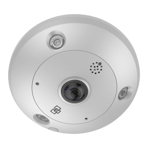
TruVision TVPA-S01-0601-360-G User manual

P/N 1092-ALL • REV A • ISS 29AUG2022
EN Installation Guide
DE Installationsanleitung
ES Guía de instalación
FR Guide d’installation
IT Guida all’installazione
NL Installatiehandleiding
PL Instrukcja instalacji
PT Guia de Instalação
TR Kurulum Kılavuzu
TruVision 360 Degree
Camera

https://resecurityproducts.com/en/bu/video

1

2

3
2.
1.

4
3.

5
4.

6
5.

7
6.

8
7.

9
8.

10
9.

11
EN
Installation environment
When installing your product, consider these
factors:
• Electrical: Install electrical wiring
carefully. It should be done by qualied
service personnel. Always use a proper
PoE-af switch or a 12 VDC UL listed
Class 2 or CE certied power supply to
power the camera. Do not overload the
power cord or adapter.
• Ventilation: Ensure that the location
planned for the installation of the camera
is well ventilated.
• Temperature: Do not operate the camera
beyond the specied temperature,
humidity, or power source ratings. The
operating temperature of the indoor
camera is between -40 °C to +60 °C. The
operating temperature of the outdoor
camera is between -40 °C to +60 °C.
Humidity 95% or less (non-condensing)
for both cameras.
• Servicing: Do not attempt to service this
camera yourself. Any attempt to dismantle
or remove the covers from this product
will invalidate the warranty and may also
result in serious injury. Refer all servicing
to qualied service personnel.
• Cleaning: Do not touch the sensor
modules with ngers. If cleaning is
necessary, use a clean cloth with some
ethanol and wipe the camera gently.
Unpacking
Check the package and contents for visible
damage. If any components are damaged
or missing, do not attempt to use the unit;
contact the supplier immediately. If the unit
is returned, it must be shipped back in its
original packaging.
Installing the camera
See pages 1 to 10.
EN
To prevent injury, the camera must be
securely attached to the ceiling or wall in
accordance with the installation instructions.
The ceiling must be strong enough to be able
to withstand more than eight times the weight
of the camera and its accessories.
Ensure that the power is disconnected before
you wire, install, or disassemble the camera.
Important: When mounting the camera to a
wall, ensure that the ‘UP’ reference on the
camera base is pointing upwards.
When re-attaching the camera cover ring,
ensure that the opening on the side of the
cover near the cover screw is not up against a
wall or ceiling. You will need to have access to
that area when removing the camera cover.
Camera description
See page 2.
1. Cover
2. MIC
3. Micro SD card slot
4. Reset button
5. Base
6. Speaker
7. Three IR illuminators
8. Camera cover ring
9. PoE+ & network port
10. 12 VDC
11. Alarm input (pins IN and G), Alarm output
(pins 1A and 1B)
12. RS-485 port
13. Audio out
14. Audio in
Supported accessories
(They are not supplied with the camera)
• TVF-BBM: TruVision 360° camera back
box

12
• TVF-CBM: TruVision 360° camera cup
base
• TVF-WBM: TruVision 360° camera round
angled back box
Local storage
Insert a Micro SD card with up to 256GB to
use the camera as an additional recording
device, or as a backup in case of failure
of communication with the network video
recorder. The card is not supplied with the
camera. Recorded video and log les can be
accessed via the web browser or via TruVision
Navigator. The camera must be connected to
a TruVision NVR to be operated by TruVision
Navigator.
Setting up the camera
Once the camera is mounted, set up its
network and streaming parameters so that
it can be controlled over the network, and
program it as appropriate for its location.
Refer to the camera’s conguration manual
for further information, which is available from
our website.
Technical specications
Electrical
Voltage input 12 VDC, PoE-af
Power consumption
12 VDC: max. 11 W,
0.9 A, two-core terminal
block.
PoE-af: 802.3af, class
0, 36 to 57 V,
0.34 to 0.22 A, max.
12.95 W
Miscellaneous
Operating
temperature -40 to +60 °C
Relative humidity 95% or less non-
condensing
IP rating:
Outdoor cameras
IP67 (TVPA-S01-0602-
360-G,
TVPA-S01-1202-360-G)
EN Dimensions:
TVPA-S01-0601-
360-G
167.4 × 152.8 × 50 mm
TVPA-S01-0602-
360-G
167.4 × 152.8 × 55mm
TVPA-S01-1201-
360-G
167.4 × 152.8 × 46.8
mm
TVPA-S01-1202-
360-G
167.4 × 152.8 × 55 mm
Weight Approx. 6.0 kg
Legal information
© 2022 Carrier. All rights reserved. The
information in this manual is subject to change
without prior notice.
TruVision names and logos are a product
brand of Aritech, a part of Carrier. Other
trade names used in this document may be
trademarks or registered trademarks of the
manufacturers or vendors of the respective
products.
While every precaution has been taken during
the preparation of this manual to ensure the
accuracy of its contents, Carrier assumes no
responsibility for errors or omissions.
Manufacturer
PLACED ON THE MARKET BY:
Carrier Fire & Security Americas Corporation,
Inc.
13995 Pasteur Blvd, Palm Beach Gardens, FL
33418, USA.
Authorized EU manufacturing representative:
Carrier Fire & Security B.V.,
Kelvinstraat 7, 6003 DH Weert, Netherlands.
Product documentation
Please scan the QR code to download
the electronic version of the product
documentation. The manuals are available in
several languages.

13
DE
Installationsumgebung
Beachten Sie beim Installieren des Produkts
folgende Faktoren:
• Elektrik: Gehen Sie bei der
Installation von elektrischen Leitungen
sorgfältig vor. Die Verkabelung
sollte von qualizierten Fachkräften
durchgeführt werden. Schließen Sie
diese Kamera ausschließlich an einen
ordnungsgemäßen PoE-af-Switch oder
an ein in der UL-Liste eingetragenes
12-V-DC-Netzteil der Klasse 2 oder
mit CE-Zulassung an. Schützen
Sie Netzkabel oder Adapter vor
Überspannung.
• Belüftung: Stellen Sie sicher, dass der
vorgesehene Installationsort der Kamera
ausreichend belüftet ist.
• Temperatur: Nehmen Sie die Kamera
nicht in Betrieb, wenn die Werte für
Temperatur, Luftfeuchtigkeit oder
Stromquelle außerhalb des angegebenen
Bereichs liegen. Die Betriebstemperatur
der Innenkamera liegt zwischen –40 °C
und +60 °C. Die Betriebstemperatur der
Außenkamera liegt zwischen –40 °C und
+60 °C. Die maximale Luftfeuchtigkeit
beträgt für beide Kameras 95 % (nicht
kondensierend).
• Wartung: Versuchen Sie nicht, die
Kamera selbst zu warten. Jeder
Versuch, das Gerät zu zerlegen oder
die Abdeckungen zu entfernen, führt
zum Verlust des Garantieanspruchs und
kann außerdem schwere Verletzungen
zur Folge haben. Überlassen Sie
DE
jegliche Wartungsarbeiten geschultem
Fachpersonal.
• Reinigung: Berühren Sie die
Meldermodule nicht direkt mit den
Fingern. Falls eine Reinigung erforderlich
ist, verwenden Sie ein mit etwas Ethanol
befeuchtetes sauberes Tuch und wischen
die Kamera damit leicht ab.
Entnahme aus der Verpackung
Überprüfen Sie Verpackung und Inhalt auf
sichtbare Beschädigungen. Wenn Teile
fehlen oder beschädigt sind, setzen Sie sich
bitte unverzüglich mit dem Lieferanten in
Verbindung. Versuchen Sie in einem solchen
Fall nicht, das Gerät in Betrieb zu nehmen.
Falls das Gerät zurückgesendet wird, muss
hierzu die Originalverpackung verwendet
werden.
Installation der Kamera
Siehe Seiten 1 bis 10.
Um Verletzungen vorzubeugen, muss die
Kamera den Installationsanweisungen
entsprechend sicher an der Decke oder
Wand angebracht werden. Die Decke muss
mit mehr als dem achtfachen Gewicht der
Kamera und ihres Zubehörs belastet werden
können.
Stellen Sie sicher, dass die Leistung
unterbrochen wurde, bevor Sie die
Kamerakabel bzw. die Kamera selbst
anbringen oder entfernen.
Wichtig: Stellen Sie bei der Montage der
Kamera an einer Wand sicher, dass die
Angabe “UP” auf dem Kamerasockel nach
oben zeigt.
Achten Sie beim Anbringen des Kamera-
Abdeckrings darauf, dass die Önung an
der Seite der Abdeckung im Bereich der
Abdeckschraube nicht zur Wand oder Decke
zeigt. Zum Abnehmen der Kameraabdeckung
muss dieser Bereich frei zugänglich sein.
Kamerabeschreibung
Siehe Seite 2.

14
1. Abdeckung
2. MIC
3. MicroSD-Kartensteckplatz
4. Reset-Taste
5. Sockel
6. Lautsprecher
7. Drei IR-Strahler
8. Kamera-Abdeckring
9. PoE+ und Netzwerkport
10. 12 V DC
11. Alarmeingang (Pins IN und G),
Alarmausgang (Pins 1A und 1B)
12. RS-485-Port
13. Audioausgang
14. Audioeingang
Geeignetes Zubehör
(nicht im Lieferumfang enthalten)
• TVF-BBM: Montagehalterung für
TruVision 360°-Kamera
• TVF-CBM: Glockenbasis für TruVision
360°-Kamera
• TVF-WBM: Runde, abgewinkelte
Montagehalterung für TruVision
360°-Kamera
Lokaler Speicher
Setzen Sie eine MicroSD-Karte mit bis zu
256 GB ein, um die Kamera für den Fall
eines Ausfalls der Kommunikation mit dem
Netzwerk-Videorekorder als zusätzliches
Aufnahme- oder Sicherungsgerät zu nutzen.
Die Karte ist nicht im Lieferumfang der
Kamera enthalten. Die aufgezeichneten
Video- und Protokolldateien können über den
Webbrowser oder über TruVision Navigator
aufgerufen werden. Die Kamera muss an
einen TruVision NVR angeschlossen sein, um
über TruVision Navigator bedient werden zu
können.
DE
Einrichten der Kamera
Richten Sie nach der Montage die
Netzwerk- und Streaming-Parameter
der Kamera so ein, dass diese über das
Netzwerk gesteuert werden kann, und
programmieren Sie sie entsprechend dem
Standort. Weitere Informationen nden Sie im
Kongurationshandbuch zur Kamera, das auf
unserer Website verfügbar ist.
Technische Daten
Elektrik
Eingangsspannung: 12 V DC, PoE-af
Leistungsaufnahme:
12 V DC: max. 11 W,
0,9 A, zweiadriger
Anschlussblock.
PoE-af: 802.3af, Klasse
0, 36 bis 57 V,
0,34 bis 0,22 A, max.
12,95 W
Weitere Angaben
Betriebstemperatur: -40 bis +60 °C
Relative
Luftfeuchtigkeit:
Max. 95 % (nicht
kondensierend)
IP-Schutzart:
Außenkameras
IP67 (TVPA-S01-0602-
360-G, TVPA-S01-1202-
360-G)
Abmessungen:
TVPA-S01-0601-
360-G
167,4 × 152,8 × 50 mm
TVPA-S01-0602-
360-G
67,4 × 152,8 × 55 mm
TVPA-S01-1201-
360-G
167,4 × 152,8 × 46,8
mm
TVPA-S01-1202-
360-G
167,4 × 152,8 × 55 mm
Gewicht: Ca. 6,0 kg
Rechtliche Hinweise
© 2022 Carrier. Alle Rechte vorbehalten. Die

15
Informationen in diesem Handbuch können
ohne Ankündigung geändert werden.
TruVision-Namen und -Logos sind
Produktmarken von Aritech, einem
Unternehmen von Carrier. Andere in diesem
Dokument verwendete Handelsnamen
können Marken oder eingetragene Marken
der Hersteller oder Anbieter der betreenden
Produkte sein.
Trotz aller Sorgfalt bei der Erstellung
dieses Handbuchs bezüglich der Richtigkeit
der Inhalte übernimmt Carrier keine
Verantwortung für Fehler oder Auslassungen.
Hersteller
AUF DEN MARKT GEBRACHT VON:
Carrier Fire & Security Americas Corporation,
Inc.
13995 Pasteur Blvd, Palm Beach Gardens, FL
33418, USA.
Autorisierter EU-Vertreter des Herstellers:
Carrier Fire & Security B.V.,
Kelvinstraat 7, 6003 DH Weert, Niederlande
Produktdokumentation
Bitte scannen Sie den QR-Code,
um die elektronische Version der
Produktdokumentation herunterzuladen.
Die Handbücher sind in mehreren Sprachen
verfügbar.
ES
Entorno de instalación
Cuando instale el producto, tenga en cuenta
los siguientes factores:
• Sistema eléctrico: instale el cableado
eléctrico con cuidado. La instalación debe
ES
realizarla personal de servicio cualicado.
Utilice siempre para la cámara un switch
PoE-af adecuado o una fuente de
alimentación de 12 V CC con la marca UL
de Clase 2 o con la certicación CE. No
sobrecargue el cable de alimentación ni el
adaptador.
• Ventilación: asegúrese de que la
ubicación prevista para instalar la cámara
está bien ventilada.
• Temperatura: no ponga en
funcionamiento la cámara por encima de
la temperatura, la humedad o los niveles
de potencia de la fuente de alimentación
especicados. La temperatura de
funcionamiento de la cámara interior
está comprendida entre -40 y +60 °C.
La temperatura de funcionamiento de la
cámara exterior está comprendida entre
-40 y +60 °C. 95 % de humedad o inferior
(sin condensación) para ambas cámaras.
• Mantenimiento: no intente realizar
operaciones de mantenimiento en la
cámara por su cuenta. Cualquier intento
de desmontar o retirar las cubiertas de
este producto invalidará la garantía.
Además, se corre el riesgo de sufrir
lesiones graves. Recurra al personal
cualicado para cualquier tarea de
mantenimiento.
• Limpieza: no toque los módulos del
sensor directamente con los dedos. Si
fuera necesario limpiarla, pase un paño
limpio con un poco de etanol sobre la
cámara con suavidad.
Desembalaje
Compruebe que el paquete y el contenido
no presenten daños visibles. Si faltan
componentes o estos presentan daños,
no intente utilizar la unidad; póngase
inmediatamente en contacto con su
proveedor. Si se devuelve la unidad, esta
debe enviarse en su embalaje original.
Instalación de la cámara
Consulte las páginas 1 a 10.

16
Para evitar lesiones, la cámara debe jarse de
forma segura al techo o la pared de acuerdo
con las instrucciones de instalación. El techo
debe ser lo sucientemente resistente como
para poder soportar más de ocho veces el
peso de la cámara y sus accesorios.
Asegúrese de que la alimentación esté
desconectada antes de cablear, instalar o
desmontar la cámara.
Importante: Cuando monte la cámara en
una pared, asegúrese de que la referencia
“ARRIBA” en la base de la cámara apunte
hacia arriba.
Al volver a colocar el anillo de la cubierta
de la cámara, asegúrese de que la abertura
lateral próxima al tornillo de la cubierta no
se encuentre contra una pared o el techo.
Deberá tener acceso a esa área cuando retire
la cubierta de la cámara.
Descripción de la cámara
Consulte la página 2.
1. Cubierta
2. MIC
3. Ranura para tarjeta micro SD
4. Botón de reinicio
5. Base
6. Altavoz
7. Tres iluminadores IR
8. Anillo de la cubierta de la cámara
9. Puerto POE+ y de red
10. 12 V CC
11. Entrada de alarma (patillas IN y G) y
salida de alarma (patillas 1A y 1B)
12. Puerto RS-485
13. Salida de audio
14. Entrada de audio
Accesorios compatibles
(No se suministran con la cámara).
ES
• TVF-BBM: caja posterior de la cámara de
360° TruVision
• TVF-CBM: base de tapa de la cámara de
360° TruVision
• TVF-WBM: caja posterior en ángulo
redondo para la cámara de 360°
TruVision
Almacenamiento local
Inserte una tarjeta Micro SD con hasta
256 GB para utilizar la cámara como un
dispositivo de grabación adicional o de
copia de seguridad en caso de fallo de
comunicación con el grabador de vídeo de
red. La tarjeta no se suministra con la cámara.
Se puede acceder a los archivos de registro
y vídeo grabados a través del navegador web
o mediante TruVision Navigator. La cámara
debe estar conectada a un NVR TruVision
para que TruVision Navigator la utilice.
Conguración de la cámara
Cuando la cámara esté montada, congure
su red y los parámetros de transmisión
para poder controlarla a través de la red
y prográmela según corresponda para
su ubicación. Consulte el manual de
conguración de la cámara, disponible
en nuestro sitio web, para obtener más
información
Especicaciones técnicas
Electricidad
Entrada de voltaje: 12 V CC, PoE-af
Consumo de
energía:
12 V CC: máx. 11 W, 0,9
A, bloque de terminales
de dos núcleos.
PoE-af: 802.3af, clase
0, de 36 a 57 V, de 0,34
a 0,22 A, máx. 12,95 W.
Varios
Temperatura de
funcionamiento: De −40 a +60 °C

17
Humedad relativa: 95 % o menos sin
condensación
Clasicación IP:
cámaras exteriores
IP67 (TVPA-S01-0602-
360-G, TVPA-S01-1202-
360-G)
Dimensiones:
TVPA-S01-0601-
360-G
167,4 × 152,8 × 50 mm
TVPA-S01-0602-
360-G
167,4 × 152,8 × 55 mm
TVPA-S01-1201-
360-G
167,4 × 152,8 × 46,8
mm
TVPA-S01-1202-
360-G
167,4 × 152,8 × 55 mm
Peso: Aprox. 6,0 kg
Información legal
© 2022 Carrier. Reservados todos los
derechos. La información de este manual
está sujeta a cambios sin previo aviso.
Los nombres y los logotipos de TruVision son
una marca de producto de Aritech, una parte
de Carrier. Los restantes nombres de marcas
utilizados en este documento pueden ser
marcas comerciales o marcas comerciales
registradas de los fabricantes o proveedores
de los respectivos productos.
Aunque se han tomado todas las
precauciones durante la elaboración de
este manual para garantizar la exactitud de
su contenido, Carrier no asume ninguna
responsabilidad por errores u omisiones.
Fabricante
COMERCIALIZADO POR:
Carrier Fire & Security Americas Corporation,
Inc.
13995 Pasteur Blvd, Palm Beach Gardens, FL
33418, EE. UU.
Representante de fabricación autorizado de
la UE:
Carrier Fire & Security B.V.,
Kelvinstraat 7, 6003 DH Weert, Países Bajos.
FR
Documentación del producto
Consulte el siguiente código QR para obtener
la versión electrónica de la documentación del
producto. Los manuales están disponibles en
varios idiomas.
FR
Lieu d’installation
Tenez compte des éléments suivants lors de
l’installation du produit :
• Caractéristiques électriques : installez
le câblage électrique avec précaution.
Cette opération doit être exécutée par
une personne qualiée. Utilisez toujours
un commutateur PoE-af approprié ou
une alimentation 12 VDC aux normes
UL, de classe 2 ou certiée CE, pour
alimenter la caméra. N’appliquez pas de
charge excessive au niveau du cordon
d’alimentation ou de l’adaptateur.
• Ventilation : assurez-vous que le lieu
dans lequel la caméra est installée est
bien aéré.
• Température : ne faites pas fonctionner
la caméra lorsque la température, le taux
d’humidité ou la source d’alimentation
n’est pas adapté(e). La température de
fonctionnement de la caméra d’intérieur
est comprise entre -40 et 60 °C. La
température de fonctionnement de
caméra d’extérieur est comprise entre -40
et 60 °C. Humidité inférieure ou égale à
95 % (sans condensation) pour les deux
caméras.
• Réparation : ne tentez pas de réparer la
caméra vous-même. Toute tentative de
démontage ou de retrait des caches de ce

18
produit entraîne l’annulation de la garantie
et peut provoquer des blessures graves.
Les réparations doivent être eectuées
par une personne qualiée.
• Nettoyage : ne touchez pas les capteurs
avec vos doigts. Si un nettoyage
s’impose, utilisez un tissu propre avec un
peu d’éthanol et frottez délicatement la
caméra.
Déballage
Vériez que l’emballage et son contenu
ne sont pas endommagés. Si l’un des
composants est endommagé ou manquant,
n’essayez pas d’utiliser la caméra ; contactez
immédiatement le fournisseur. Si la caméra
doit être retournée, utilisez l’emballage
d’origine.
Installation de la caméra
Voir pages 1 à 10.
Pour éviter les blessures, la caméra doit
être solidement xée au plafond/mur
conformément aux instructions d’installation.
Le plafond doit être susamment solide pour
pouvoir supporter plus de huit fois le poids de
la caméra et de ses accessoires.
Assurez-vous que l’alimentation est
débranchée avant de câbler, installer ou
démonter la caméra.
Important : lors du montage de la caméra sur
un mur, assurez-vous que la mention « UP
» sur la base de la caméra pointe vers le haut.
Lorsque vous remettez en place la bague
de protection de la caméra, assurez-vous
que l’ouverture située à proximité de la vis
du couvercle n’est pas en contact avec le
mur ou le plafond. Vous devez avoir accès à
cette zone lors du retrait du couvercle de la
caméra.
Description de la caméra
Reportez-vous à la page 2.
1. Couvercle
2. MIC
FR
3. Emplacement pour carte microSD
4. Bouton Réinitialiser
5. Base
6. Haut-parleur
7. Trois voyants IR
8. Bague de protection de la caméra
9. Port PoE+ et réseau
10. 12 VDC
11. Entrée alarme (broches IN et G), sortie
alarme (broches 1A et 1B)
12. Port RS-485
13. Sortie audio
14. Entrée audio
Accessoires pris en charge
(non fournis avec la caméra)
• TVF-BBM : boîtier arrière de la caméra
TruVision 360°
• TVF-CBM : base de la caméra TruVision
360°
• TVF-WBM : boîtier arrière à angle rond
pour caméra TruVision 360°
Stockage local
Insérez une carte microSD protant
d’une capacité allant jusqu’à 256 Go an
d’utiliser la caméra en tant que périphérique
d’enregistrement supplémentaire, voire de
périphérique de sauvegarde en cas d’échec
de la communication avec l’enregistreur
vidéo réseau. Aucune carte SD n’est fournie
avec la caméra. Les chiers enregistrés et
journaux sont accessibles via le navigateur
Web ou TruVision Navigator. La caméra doit
être connectée à un NVR TruVision pour être
commandée par TruVision Navigator.
Paramétrage de la caméra
Une fois la caméra montée, congurez son
réseau et ses paramètres de diusion an
qu’elle puisse être contrôlée sur le réseau,
et programmez-la en fonction de son
This manual suits for next models
3
Table of contents
Languages:
Other TruVision Digital Camera manuals

TruVision
TruVision TVW-DVM User manual
TruVision
TruVision TVF-5201 Instruction sheet
TruVision
TruVision M Series User manual
TruVision
TruVision TVPA-S01-1202-360-G Instruction sheet
TruVision
TruVision S Series User manual
TruVision
TruVision TVGP-P01-0201-PTZ-G User manual
TruVision
TruVision HD-TVI User manual
TruVision
TruVision TVD-CB3 Cup Base User manual
