tryten Nova Go User manual

Nova Go/Pro/Neo Assembly Instructions –Rev K Page 1
Nova Mobile Carts 1-800-860-4455
Tryten Nova Go/Pro/Neo Line
Assembly Instructions
For further instructions please visit Tryten.com/instructions.
For additional questions or technical support contact us at
Tryten.com/contact or 1-800-860-4455.

Nova Go/Pro/Neo Assembly Instructions –Rev K Page 2
Assembly Instructions Page
Receiving the Shipping Box 4
Assembling Pole to Base 5
Universal OmniTab Adjustment 6-8
Removing Channel Strips 9
Nova Go Universal OmniTab Installation 9
Power Box and Cabling Installation 10
Device Height Adjustment 11
Work Surface Installation 12
Supply Caddy and Transducer Holder Installation 13
Supply Caddy Lockable Lid 14-15
Nova Go VESA Bracket and Monitor
Installation 16
Nova Neo Vertical Tablet Arm Installation 17
Nova Go and Pro VESA Plate Installation 17
Yeti-200 Battery Bracket Installation 18
Wire Basket Installation 19
Poly SY20 Speaker installation 20
Butterfly Bracket Installation 21
Speaker Bracket and Speaker Installation 22-23

Nova Go/Pro/Neo Assembly Instructions –Rev K Page 3
NOVA HARDWARE PACK
•Felt Pads –3/4” x 1/8” thick (6)
•Label Hardware Kit Nova (1)
•Hex L-Key - 3/16” size (1)
•Torx Security L-Key - T25 (1)
•Hex L-Key - 5/32” size (1)
•Keys Set Tablet Cart Nova (1)
•Screw 10-24 x 3/4" Security Torx, Button head, SS (1)
•Screw 1/4-20 by 1" Socket Head, Zinc (4)
•Belleville (dome) Washer 1/4" 18-8 SS (4)
ADDITIONAL TOOLS NEEDED FOR INSTALLATION
•Scissors for cutting channel cover to length
ASSEMBLY INSTRUCTIONS
Note: Shipping box pictures show Nova Pro Tablet Cart for
assembly reference. Configurations may vary, but the installation
process will be similar.
INSTALLATION OF ACCESSORIES TO THE CARTS
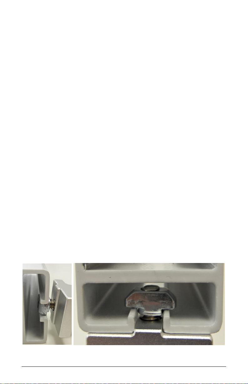
Note: When installing accessories, the Z or T-Nut has to be loose
and aligned vertically (up/down) when inserted into the extrusion
channel. Once adjusted at the desired height, tighten the screw
until it is fully locked to the extrusion. Always verify that the nut is
aligned horizontally (left/right) when fully tightened.

Nova Go/Pro/Neo Assembly Instructions –Rev K Page 4
1. RECEIVING THE SHIPPING BOX
•Base.
•Extract the Hardware pack.
•Remove Pole Assembly from packaging.

Nova Go/Pro/Neo Assembly Instructions –Rev K Page 5
2. ASSEMBLING POLE TO BASE
•Assemble the Pole to the base with the four (4) screws and
dome washers using the 3/16”Hex L-Key from the
Hardware Pack.

Nova Go/Pro/Neo Assembly Instructions –Rev K Page 6
3. (A) UNIVERSAL OMNITAB ADJUSTMENT
The Universal bracket comes adjusted to fit the standard iPad 9.7
•Unlock the Top Slider using the set of keys from the
Hardware Pack. Remove the Top Slider from the Universal
Bracket.
•Loosen the three (3) screws using the 1/8”Hex L-Key from
the front of the cover.
•Pull the sliders to the appropriate size tablet.
•Tighten the three (3) adjustment screws.
•Insert tablet by sliding in from the top.
•Insert the Top Slider until it locks in the tablet and push
the locking button.

Nova Go/Pro/Neo Assembly Instructions –Rev K Page 7
3. (B) INSTALLING 2ND SET OF SLIDERS FOR TABLET WITH
CASE
•Remove the four (4) Felt Pads from the Universal Bracket.
•Remove the four (4) screws holding the cover of the
Universal Bracket using the 1/8”Hex L-Key from the front
of the cover.
•Remove cover and the three (3) screws holding the sliders
using the 1/8”Hex L-Key from the front of the cover.

Nova Go/Pro/Neo Assembly Instructions –Rev K Page 8
•Remove the four (4) sliders and replace with the set of
sliders from Hardware Pack.
•Install the three (3) Screws holding the sliders using the
1/8”Hex L-Key from the front of the cover.
•Put back the cover and install the four (4) screws removed
at step b) using the 1/8” Hex L-Key from the front of the
cover.
•Apply the set of felt pads supplied in the hardware pack on
top of the screws.
•Adjust sliders and install tablet, following the instructions
from Step 3A.

Nova Go/Pro/Neo Assembly Instructions –Rev K Page 9
•Insert one (1) of the smaller Allen L-Keys behind the top of
the channel cover to pull out of the pole. Reinstall covers
after the power cords are in place.
Note: Channel Cover Strips will need to be adjusted if
accessories are installed.
5. NOVA GO UNIVERSAL OMNITAB INSTALLATION
•Extract the Nova Go head from packaging box and the Torx
Security Button Head Screw from the Hardware Pack.
•Assemble the Nova Go head as shown using the Torx
Security L-Key provided in the Hardware Pack.
•Tighten the screw until it is fully engaged.
4. REMOVING THE CHANNEL STRIPS

Nova Go/Pro/Neo Assembly Instructions –Rev K Page 10
6. POWER BOX AND CABLING INSTALLATION
•Install Utility box by loosening Z-Nuts, insert Z-Nuts into
extrusion channel, slide box up or down to desired height
and tighten screws.
•Open box by using Torx Security L-Key, loosen two (2)
screws from the back of the Power Box until cover swings
open.
•Install 9’ Green Dot Hospital Grade Power Extension Cable
as shown (see middle image).
•Install tablet’s power cable through hole and up the
channel as shown.
•Close door back in place and re-install the screws from
back.
STORING THE POWER CORD
When the cart is not in use, or tablet is not being charged, the
extension cord should be wrapped and stored on the unit. Wrap
the cable firmly around the upper handle and lower handle Cord
Wraps located on the back of the unit pole.

Nova Go/Pro/Neo Assembly Instructions –Rev K Page 11
7. DEVICE HEIGHT ADJUSTMENT
•In order to adjust the height of the surface or keyboard tray, the
handle may need to rotate to add more turns. The handle is
spring loaded so it can be rotated to a different position to
tighten the assembly. With assembly loose, move assembly to
desired height. Tighten the handle and lock the device in place
by turning the handle clockwise. If the handle cannot turn
anymore and the assembly is not yet tight, pull the handle out
(image 1), rotate counterclockwise and release handle back in
place (image 3) to tighten the assembly. Repeat process until
device is fully tightened.
•Work Surface adjustment
•Keyboard Tray adjustment

Nova Go/Pro/Neo Assembly Instructions –Rev K Page 12
8. NOVA PRO WORK SURFACE INSTALLATION
•Remove channel cover strip (ref. point 4).
•Remove articulating arm or tall pole with one (1) screw
using Torx Security L-Key provided in hardware pack.
•Remove extrusion adapter by removing two (2) 1/4”
screws with 3/16” Hex L-Key provided.
•Slide Work Surface down from top and secure at desired
height (ref. point 7).
•Reinstall Extrusion Adapter and Arm.

Nova Go/Pro/Neo Assembly Instructions –Rev K Page 13
9. SUPPLY CADDY & TRANSDUCER HOLDER INSTALLATION
The Supply Caddy and Transducer Holder each come in two (2)
parts –the Caddy/Holder and the Mounting Bracket and
Hardware to attach to the pole.
•Remove channel cover strip (ref. point 4).
•Install Caddy/Holder bracket with two (2) 1/4” Screws and
two (2) Z-Nuts as shown below with 5/32” L-Key provided
in hardware pack.
•Adjust bracket to desired height and tighten screws.
•Slide the Supply Caddy or Transducer Holder onto the
Mounting Bracket from above until it snaps in place.

Nova Go/Pro/Neo Assembly Instructions –Rev K Page 14
9.1 SUPPLY CADDY LOCKABLE LID
•Loosen Z-Nut from screw but do not remove.
•Rotate Z-Nut so it slides into the channel.
•Lower entire lid until it rests on the Caddy.
•Fasten lid to pole by using Torx Security L-Key (provided)
and turn screw until tight.

Nova Go/Pro/Neo Assembly Instructions –Rev K Page 15
9.2 SETTING PERSONAL COMBINATION NUMBERS
•Factory combination is set at 0-0-0
•Combination must be on opening numbers prior to
resetting.
•You will find a hole on the outer ring for code reset, see
picture.
•Rotate lock until reset button comes into view.
•Push pin with paper clip or small pin and keep it pushed in.
•Set numbers to desired combination.
•Release button and your new combination is set.
To lock, rotate to ‘locked’ position, rotate one or more dials.
To unlock, rotate dials to personal combination and ‘unlock’.

Nova Go/Pro/Neo Assembly Instructions –Rev K Page 16
10. NOVA GO VESA –FIXED VESA BRACKET & MONITOR
INSTALLATION
•Remove channel cover strip (ref. point 4).
•Install bracket to extrusion with two (2) screws and two (2)
Z-Nuts.
Note: Ensure the thicker section of the bracket is
mounted at the top.
•Install VESA plate to bracket with four (4) button head
screws.
•Install Monitor to VESA plate with four (4) mounting
screws (not included).

Nova Go/Pro/Neo Assembly Instructions –Rev K Page 17
11. NOVA NEO –VERTICAL TABLET ARM INSTALLATION
•Remove channel cover strip (ref. point 4).
•Install Adapter Plate to extrusion with two (2) screws and
two (2) Z-Nuts provided.
12. NOVA PRO/GO VESA –VESA PLATE INSTALLATION
•Install VESA Mount Plate to adapter with four (4) Button-
Head Screws.
•Install monitor or device to VESA Plate with four (4)
mounting screws (not included).

Nova Go/Pro/Neo Assembly Instructions –Rev K Page 18
13. YETI 200 BRACKET INSTALLATION
•Remove channel cover strip (ref. point 4).
•Install Yeti 200 platform bracket to extrusion by having
two (2) screws and T-Nuts loose, insert into the extrusion
channel, move up or down to desired position and tighten
screws.
•Place battery on platform.
•Place handle bracket around the green handle as the Z-Nut
is inserted into the channel, place bracket on battery and
tighten screw.

Nova Go/Pro/Neo Assembly Instructions –Rev K Page 19
14. WIRE BASKET INSTALLATION
•Remove channel cover strip (ref. point 4).
•Loosen two (2) Z-Nuts but do not remove, place Z-Nuts
into the extrusion channel, move basket to desired height.
•Tighten wire basket to extrusion with two (2) screws and
two (2) Z-Nuts.

Nova Go/Pro/Neo Assembly Instructions –Rev K Page 20
15. POLY SY20 SPEAKER INSTALLATION
•Remove channel cover strip (ref. point 4).
•Loosen T-Nut but do not remove, place T-Nut into the
extrusion channel, move bracket up or down to desired
height.
•Tighten bracket to extrusion with screw and T-Nut.
•Slide speaker back ridge into the fixed bracket, slide clamp
bracket onto speaker and align two (2) screw holes.
•Install and tighten two (2) screws.
This manual suits for next models
2
Table of contents
Other tryten Medical Equipment manuals
Popular Medical Equipment manuals by other brands

KaVo
KaVo DIAGNOcam Vision Full HD Instructions for use

DJO Global
DJO Global ARTROMOT-E2 COMPACT operating instructions

MOXTEK
MOXTEK MAGNUM X-ray quick start guide

Siemens
Siemens MOBILETT Plus Service instructions

Air Liquide
Air Liquide Osiris 2 manual

College Park
College Park venture Technical instructions