tryten Nova Line User manual

Nova Assembly Instructions – Rev G Page 1
Nova Mobile Carts 1-800-860-4455
Tryten Nova Line
Assembly Instructions
For further instructions please visit Tryten.com/instructions, for
additional questions or technical support contact us at
Tryten.com/contacts or 1-800-860-4455.

Nova Assembly Instructions – Rev G Page 2
Assembly Instructions Page
Receiving the Shipping Box 3-4
Assembling Base to Pole 5
Universal Omnitab Adjustment 6-9
Removing Channel Strips 10
Nova Go Universal Omnitab Installation 10
Power Box and Cabling Installation 11
Extension Pole installation, Neo and Connect 12
Work Surface Installation 13-15
Keyboard Tray Installation 16
Supply Caddy and Transducer Holder Installation 17
Supply Caddy Lockable Lid 18-19
Nova Connect and Tall Vesa bracket and Monitor
Installation
20-21
Nova Neo Vertical Tablet Arm Installation 22
Nova Go and Pro Vesa Plate Installation 22
Nova Connect and Tall Camera Bracket Installation 23-24
Logitech Bracket and Camera Installation 25-26
Speaker Bracket and Speaker Installation 27-29
Intel NUC Bracket and Unit Installation 30

Nova Assembly Instructions – Rev G Page 3
NOVA HARDWARE PACK
•Felt Pads - ¾” x 1/8” thick (6)
•Label Hardware Kit Nova (1)
•Hex L-Key - 3/16” size, 3” length (1)
•Torx Security L-Key - T25, 2-11/16” long (1)
•Hex L-Key - 5/32” size, 2-11/16” length (1)
•Keys Set Tablet Cart Nova (1)
•Screw 10-24 x 3/4" Security Torx, Button head, SS (1)
•Screw 1/4-20 by 1" Socket Head, Zinc (4)
•Belleville (dome) Washer 1/4" 18-8 SS (4)
ASSEMBLY INSTRUCTIONS
Note: Shipping box pictures show Nova Pro Tablet Cart for
assembly reference. Alternative configurations vary but the
installation process is similar.
1. OPEN THE SHIPPING BOX
•Base

Nova Assembly Instructions – Rev G Page 4
Extract the Hardware pack.
•Remove Pole Assembly from packaging.
Nova Assembly Instructions – Rev G Page 5
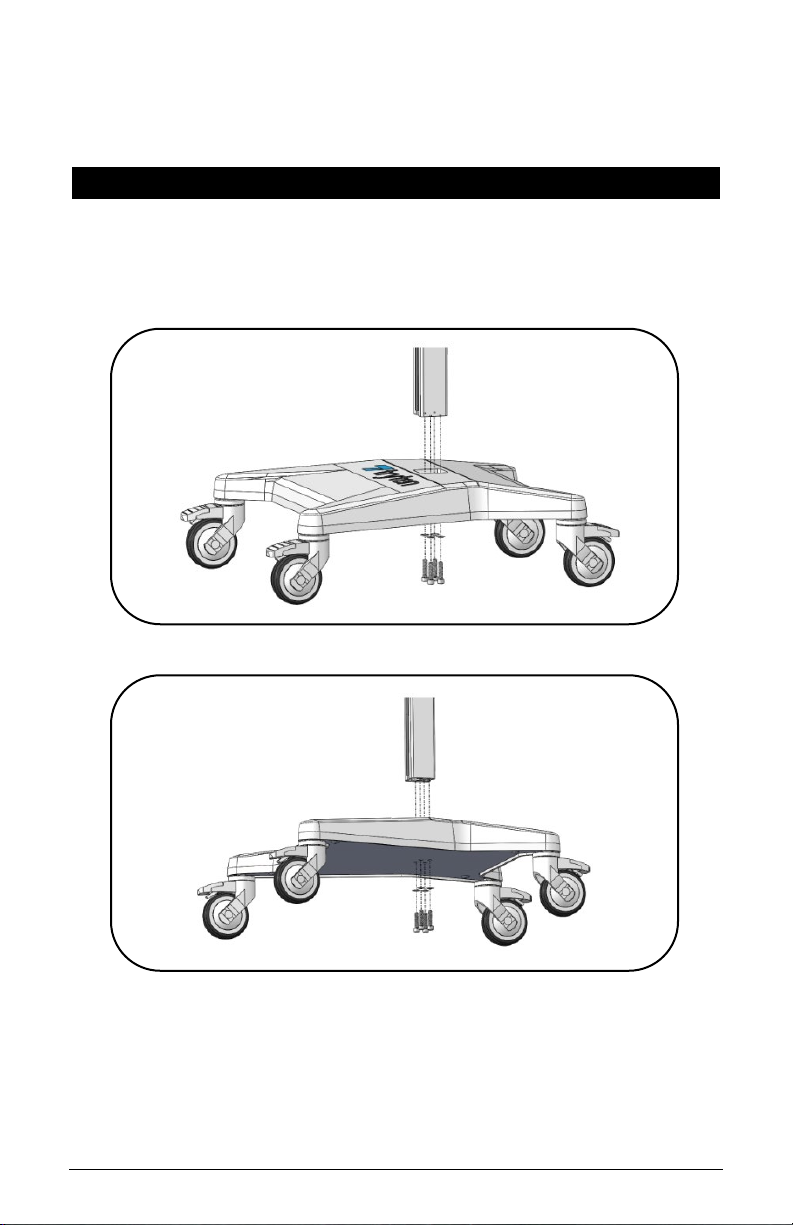
2. ASSEMBLE THE POLE
•Assemble the Pole to the base with the four (4) screws and
dome washers using the 3/16” Hex L-Key from the
Hardware Pack.
Nova Assembly Instructions – Rev G Page 6
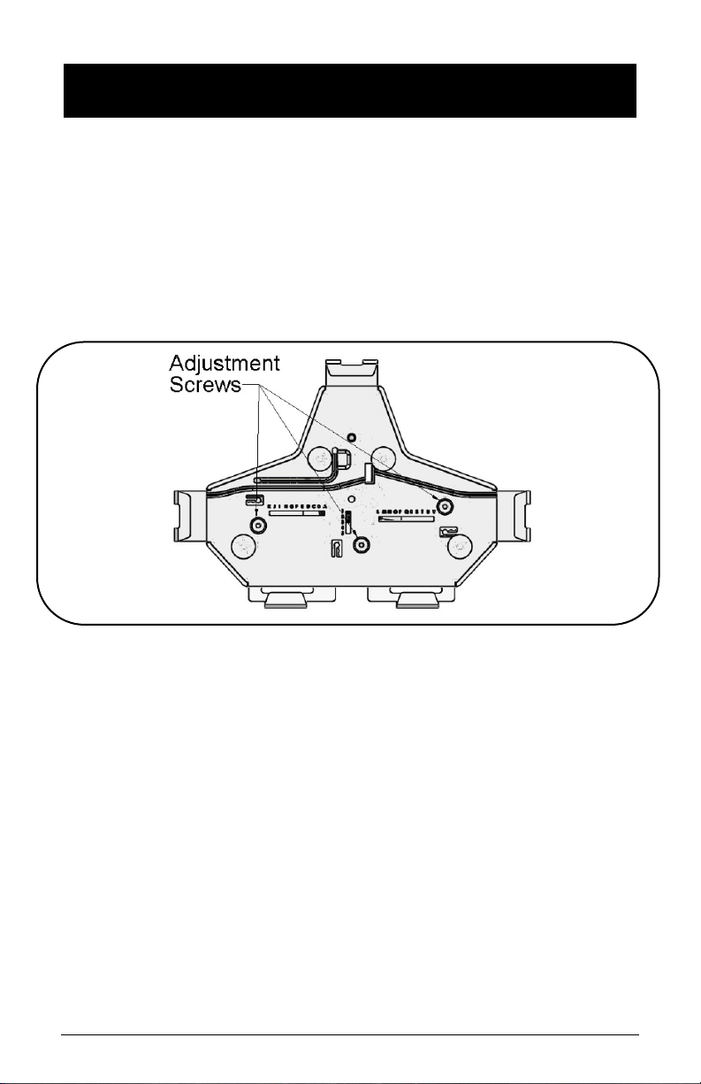
3. (A) ADJUST OMNITAB UNIVERSAL BRACKET TO FIT
TABLET
The Universal bracket comes adjusted to fit the standard iPad 9.7
•Unlock the Top Slider using the set of keys from the
Hardware Pack. Remove the Top Slider from the Universal
Bracket.
•Loosen the three (3) screws using the 1/8” Hex L-Key from
the front of the cover.
•Pull the sliders to the appropriate size tablet
•Tighten the 3 adjustment screws
•Insert tablet by sliding in from the top.
•Insert the Top Slider until it locks in the tablet and push
the locking button.

Nova Assembly Instructions – Rev G Page 7
3. (B) INSTALLING 2ND SET OF SLIDERS WHEN TABLET IN
CASE
•Remove the 4 Felt Pads from the Universal Bracket.
•Remove the 4 Screws holding the cover of the Universal
Bracket using the 1/8-inch Hex L-Key from the front of the
cover.

Nova Assembly Instructions – Rev G Page 8
•Remove cover and the 3 screws holding the sliders using
the 1/8-inch Hex L-Key from the front of the cover.
•Remove the 4 sliders and replace with the set of sliders
from Hardware Pack.
•Install the 3 Screws holding the sliders using the 1/8-inch
Hex L-key from the front of the cover.

Nova Assembly Instructions – Rev G Page 9
•Put back the cover and install the four (4) screws removed
at step b) using the 1/8” Hex L-Key from the front of the
cover.
•Apply the set of felt pads supplied in the hardware pack on
top of the screws.
•Adjust sliders and install tablet following the instructions
from Step 3A

Nova Assembly Instructions – Rev G Page 10
•Insert one of the smaller Allen Keys in behind the top of
the channel cover to pull out of the pole. Reinstall covers
after the power cords are in place.
Note: Channel Cover Strips will need to be adjusted if
accessories are installed.
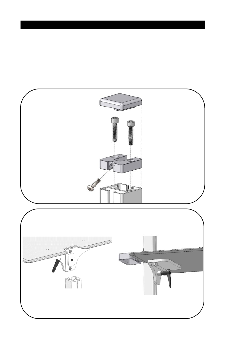
5. NOVA GO HEAD INSTALLATION
•Extract the Nova Go head from packaging box and the Torx
Security Button Head Screw from the Hardware Pack.
•Assemble the Nova Go head as shown using the Torx
Security L-Key provided in the Hardware Pack.
•Tighten the screw until it is fully engaged.
4. REMOVE THE CHANNEL STRIPS

Nova Assembly Instructions – Rev G Page 11
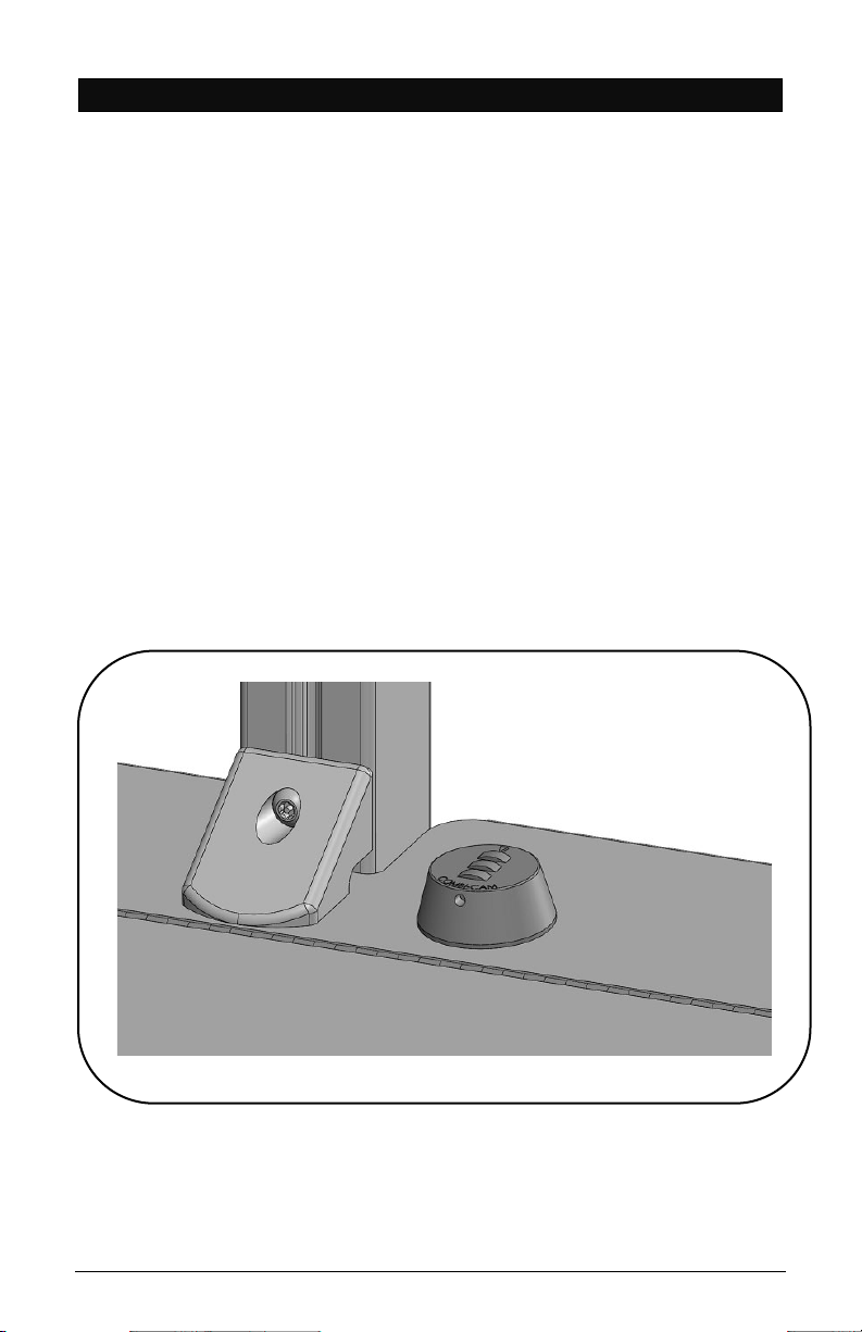
6. POWER BOX AND CABLING INSTALLATION
•Open box by using Torx security L-Key, loosen and remove
the 2 screws located on the back of the Power Box.
•Lift cover up or down to remove.
•Install 9’ Green Dot Hospital Grade Power Extension Cable
as shown.
•Install tablet’s power cable through hole and up the
channel as shown.
•Slide the Power Box Cover back in place and re-install the
screws.
STORING THE POWER CORD
When the cart is not in use, or tablet is not being charged, the
extension cord should be wrapped and stored on the unit. Wrap
the cable firmly around the upper handle and lower handle cord
wraps located on the back of the unit pole.
Nova Assembly Instructions – Rev G Page 12
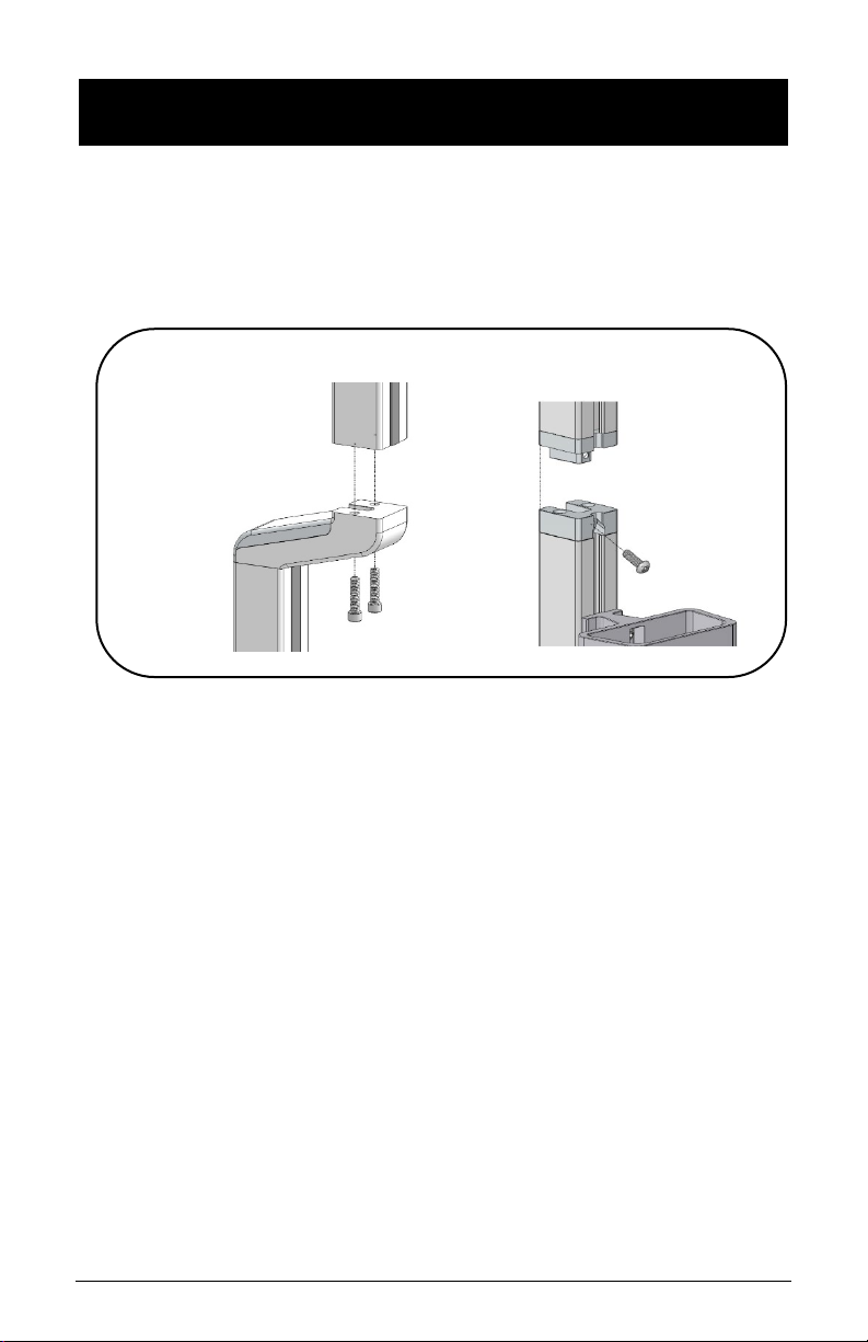
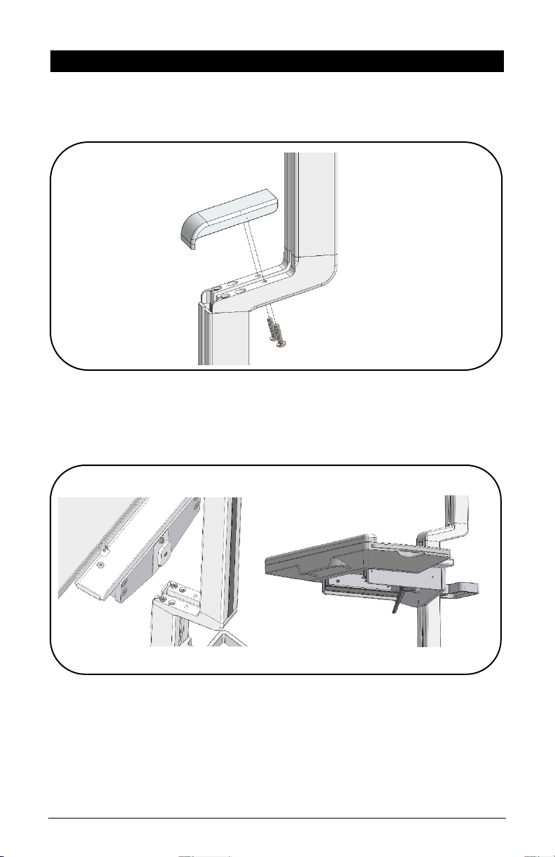
7. EXTENSION POLE INSTALLATION, NOVA CONNECT AND
NOVA NEO
•On the nova connect, shown below left, assemble the
extension pole to the offset adapter with the 2 screws (1”)
using the 3/16” Allen key.
•On Nova Neo, shown below right, assemble with 1 screw
using Torx security L-Key provided in hardware pack.
Nova Assembly Instructions – Rev G Page 13
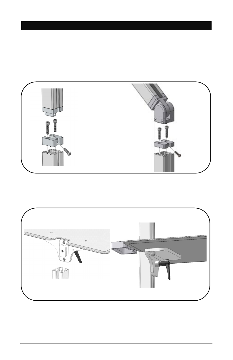
8. NOVA PRO AND TALL WORK SURFACE INSTALLATION
•Remove Channel Cover Strip (ref. point 4).
•Remove articulating arm or tall pole with 1 screw using
Torx security L-Key provided in hardware pack.
•Remove extrusion adapter by removing (2) ¼” screws with
3/16” L-key provided.
•Slide Work Surface down from top and secure at desired
height.
•Reinstall Extrusion Adapter and Arm or tall pole.
Nova Assembly Instructions – Rev G Page 14
9. NOVA MOTION – WORK SURFACE INSTALLATION
•Remove Channel Cover Strip (ref. point 4).
•Remove Pole Cap with rear screw using Torx Security L-Key
•Remove Extrusion Adapter with two (2) screws from top
using 3/16” hex L-key
•Slide Work Surface down from top and secure at desired
height.
•Reinstall extrusion adapter and pole cap.
Nova Assembly Instructions – Rev G Page 15
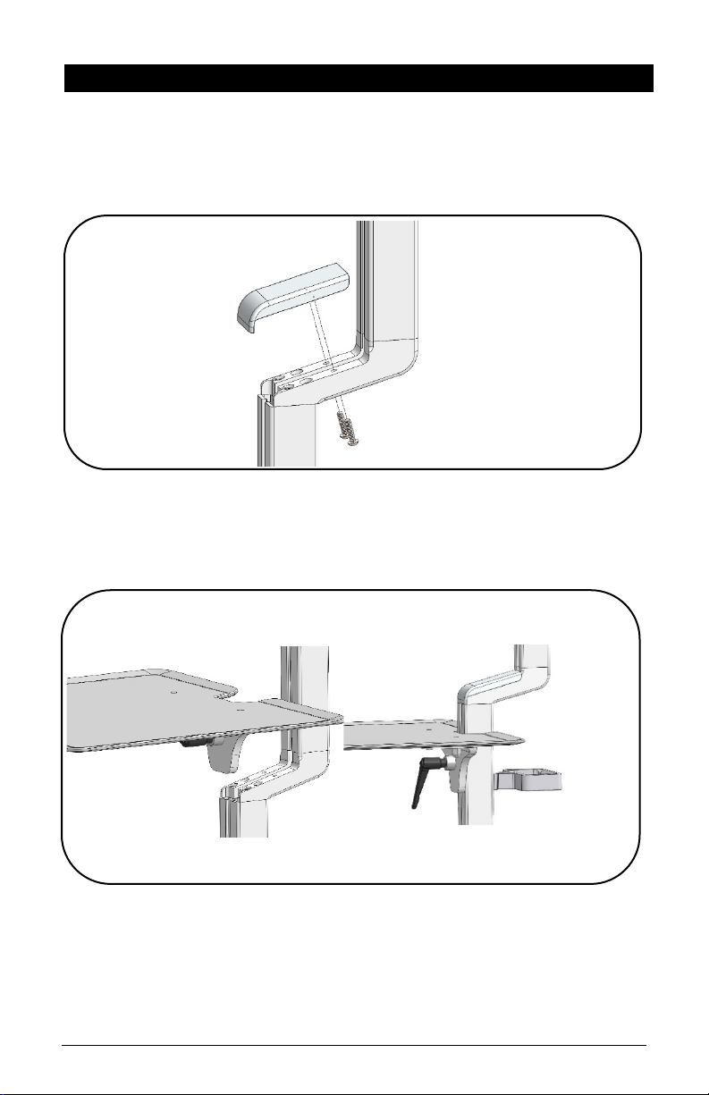
10. NOVA CONNECT – WORK SURFACE INSTALLATION
•Remove Channel Cover Strip (ref. point 4).
•Remove two (2) screws from underneath to remove offset
adapter cap using Torx security L-key provided.
•Slide keyboard tray down channel from top, set and lock
with handle at desired height.
•Re-install offset adapter cap.
Nova Assembly Instructions – Rev G Page 16
11. KEYBOARD TRAY INSTALLATION
•Remove channel cover from front extrusion (ref. step 5).
•Remove two (2) screws from underneath to remove offset
adapter cap using Torx Security L-Key provided.
•Slide keyboard tray down channel from top, set and lock
with handle at desired height.
•Re-install offset adapter cap to pole.
Nova Assembly Instructions – Rev G Page 17
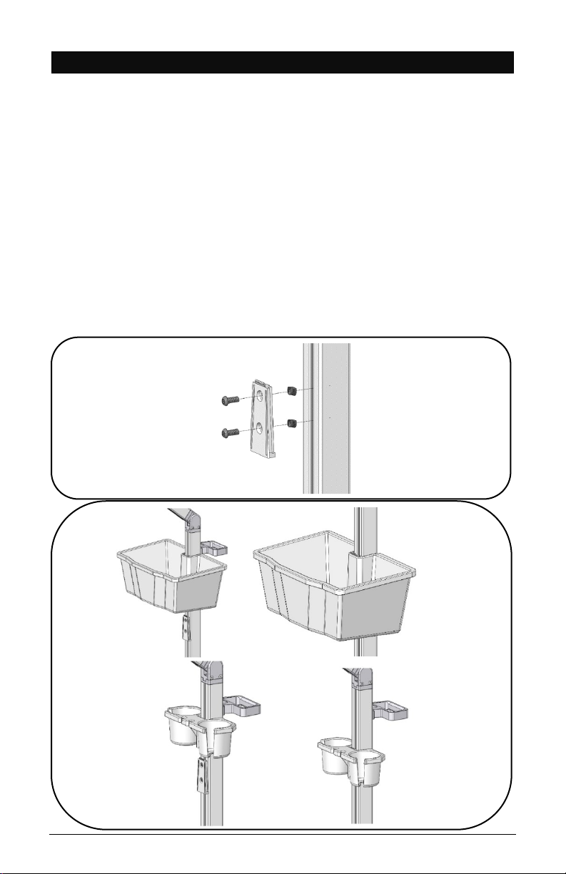
12. SUPPLY CADDY & TRANSDUCER HOLDER INSTALLATION
The Supply Caddy and Transducer Holder each come in two (2)
parts – the Caddy/Holder and the Mounting Bracket and
Hardware to attach to the pole.
•Remove Channel Cover Strip (ref. point 4).
•Install Caddy/Holder bracket with two (2) ¼” Screws and
two (2) Z-Nuts as shown below with 5/32” L-key provided
in hardware pack.
•Adjust bracket to desired height and tighten screws.
•Slide the Supply Caddy or Transducer Holder onto the
Mounting Bracket from above until it snaps in place.

Nova Assembly Instructions – Rev G Page 18
12.1 SUPPLY CADDY LOCKABLE LID
•Loosen Z-nut from screw but do not remove.
•Rotate Z-nut so it slides into the channel.
•Lower entire lid until it rests on the Caddy.
•Fasten lid to pole by using Torx security L-key (provided)
and turn screw until tight.
12.1 S
Nova Assembly Instructions – Rev G Page 19
12.2 SETTING PERSONAL COMBINATION NUMBERS
DY KABLE LID
•Factory combination is set at 0-0-0
•Combination must be on opening numbers prior to
resetting.
•You will find a hole on the outer ring for code reset, see
picture.
•Rotate lock until reset button comes into view.
•Push pin with paper clip or small pin and keep it pushed in.
•Set numbers to desired combination.
•Release button and your new combination is set.
To lock, rotate to ‘locked’ position, rotate one or more dials.
To unlock, rotate dials to personal combination and ‘unlock’.

Nova Assembly Instructions – Rev G Page 20
13. NOVA CONNECT & TALL – FIXED VESA BRACKET &
MONITOR INSTALLATION
•Remove Channel Cover Strip (ref. point 4).
•Install bracket to extrusion with two (2) screws and two (2)
Z-Nuts.
Note: Ensure the thicker section of the bracket is
mounted at the top
•Install VESA plate to bracket with four (4) button head
screws.
•Install Monitor to VESA plate with four (4) mounting
screws (not included).
Other manuals for Nova Line
1
Table of contents
Other tryten Medical Equipment manuals


