TTI PL Series User manual

PL Series
Power Supplies
Service Manual
Book Part Number 48511-0150

Table of Contents
General 1
Specification 3
Installation 6
Functional Description – Main Outputs 9
Circuit Description – Main Outputs 10
Calibration – Main Outputs 12
Quad Mode Calibration 13
Quad Mode Triples 14
Funcitonal Description - 5V/7A Module (PL330 QMT) 14
Circuit Description - 5V/7A (Issue 2 PCBs and later) 14
Calibration - 5V/7A Module 17
Functional Description - 5V/4A Module (PL320QMT) 18
Circuit Description - 5V/4A 18
Calibration - 5V/4A 19
Circuit Description - 5V/1.5A (PL310QMT) 19
Parts List 20
Component Layouts & Circuit Diagrams 38
General
Applicability of this Manual
This Service Manual is for the revised PL models introduced from mid-1991, with the exception of
the PL-P 3Amp programmable models which are covered by a separate manual. The revised PLs
differ substantially in their circuit configurations from their predecessors whilst functionally
remaining very similar; the new models can, however, be very easily distinguished from the
earlier series because they have a push-button current damping switch instead of a panel-
mounted rocker switch. The earlier PLs are covered by separate manuals for the manual and
programmable versions.
Introduction
The PL series of power supplies are fully variable series regulated units incorporating separate
digital meters for voltage and current. Separate voltage and current control circuits enable them
to operate in constant voltage or constant current mode from 0 to 32 Volts at 0 to 1.1 Amps, 2.1
Amps or 3.1 Amps (0 to 15 Volts at 4 Amps - PL154); triple versions have additional 5 Volt logic
supply outputs.
In addition to the AC input switch, there is a DC output switch. When this switch is 'off', the +ve
output is disconnected and the current meter reads the value of the current control setting. The
current meter decimal points are used to indicate the mode as follows:
Decimal points off - output switch 'on', constant voltage operation, meter reading output current.
Decimal points on - output switch 'off', meter reading current limit setting
Decimal points flashing - output switch 'on' constant current operation, meter reading output current.
1

A damping switch is incorporated on the current meter. This provides a long time constant which
averages out rapidly fluctuating load currents.
The input to the voltage control circuit and voltage meter are brought out to the front panel
terminals labelled 'sense'. These are normally connected to the output terminals by shorting
bars, but can be connected to the output at the load via separate leads in order to eliminate
inaccuracies caused by lead resistances.
Quad Mode Dual (QMD) versions incorporate push button switches enabling Isolated, Parallel,
Series, or Series Tracking operations to be selected. Quad Mode Triple (QMT) units are the
same as the QMD supplies but have an additional higher current 5V output intended for powering
logic circuits. The current rating and sophistication of the logic output varies according to the
model from 5 Volt fixed at 1.5 Amp maximum to 4-6 Volt variable with a 0.1 - 7 Amp variable
current limit.
General and Safety
This manual has been prepared to aid the experienced engineer in the maintenance and repair of
PL Series power supplies. It should be used in conjunction with the owner's instruction manual.
Recalibration or repair should only be attempted by skilled personnel in conjunction with high
quality test equipment. If the user is in any doubt as to his competence to carry out the work, the
supply should be returned to the manufacturer or their agent overseas for the work to be carried
out.
When the power supply is connected to the AC line, terminals may be live, and the opening of
covers or removal of parts (except those to which access can be gained by hand) is likely to
expose live parts.
The supply shall be disconnected from all voltages sources before it is opened for any
adjustment, replacement, maintenance or repair. Capacitors inside the supply may still be
charged even if the supply has been disconnected from all voltage sources. Any adjustment,
maintenance or repair of the opened supply under voltage shall be avoided as far as possible
and, if inevitable, shall only be carried out by a skilled person who is aware of the hazard
involved.
Dismantling the Equipment
The cover is removed by removing the two screws through the handle, and the remaining screws
on each side and on the top.
The front panel may be disconnected from the chassis by removing the two front feet and the
self-tapping screws directly between them. This allows the front panel to be laid forward giving
improved access to the rear of the PCB. All preset adjustments are accessible through the PCB.
Should it be necessary to gain access to the front of the PCB, press in the retaining barb on each
corner fixing pillar and lift off the pcb, having first removed the 3 control knobs.
2

Specification
Main Output(s)
Output Range: 0-32 Volts nominal (0-15.5V PL154)
0-1.1A nominal (PL310); 0-2.1A nominal (PL320);
0-3.1A nominal (PL330); 0-4A (PL154)
Output Voltage Setting: By coarse and fine controls; resolution better than 5mV across the
range.
Output Current Setting: By single logarithmic control.
Output Mode: The power supply operates in constant current or constant voltage
modes with automatic cross-over. Decimal points flash to indicate
constant current mode.
Configuration Selection: (QMD
and QMT only)
Isolated, True parallel, Series, or Series Tracking via front panel
switches.
Output Switch: Isolates the output and permits voltage and current limits to be set
up before connecting the load.
Output Terminals: 4mm terminals on 19mm (.75") spacing.
Output Impedance:
Constant Voltage: Typically <5mOhm at 1kHz
Constant Current: Typically 50kOhm with voltage limit at maximum
Output Protection: Up to maximum output voltage +20 Volts forward; diode clamped
for reverse voltages and up to 3A reverse current.
Load Regulation: <0.01% of maximum output for 90% load change
Line Regulation: <0.01% of maximum output for 10% line voltage change
Remote Sense: Eliminates up to 0.5V drop per lead
Ripple and Noise: Typically <1mV rms
Transient Response: <20usec to within 50mV of setting for 90% load change
Temperature Coefficient: Typically <100ppm/_o_C
Meter Type: Dual 3.75 digit (4095 count) with 12.5mm (0.5") LEDS. Reading
rate 4 per second.
Meter Resolution:
Voltage: 10mV over the entire range
Current: 1mA over the entire range
Meter Accuracy:
Voltage: 0.1% of reading
Current: 0.3% of reading
Current Meter Damping: Nominally 20ms, switchable to 2 sec for averaging of rapidly
varying loads.
3

Logic Output (PL330 QMT)
Output Voltage Range: 4 to 6 Volts
Output Current: 0.1 to 7 Amps.
Output Switch: Electronic
Output Terminals: 4mm terminals on 19mm (.75") spacing.
Over-Voltage Protection: Above 7 Volts
Output Protection: Clamped by the over-voltage protection circuit for forward voltages
over 7 Volts and up to 1 Amp forward current. Diode clamped for
reverse voltages and up to 3 Amps reverse current.
Load Regulation: <0.01% of maximum output for 90% load change
Line Regulation: <0.01% of maximum output for 10% line voltage change
Remote Sense: Eliminates up to 0.5V drop per lead
Ripple and Noise: Typically <1mV rms
Transient Response: <20usec to within 50mV of setting for 90% load change
Temperature Coefficient: Typically <100ppm/°C
Meter Type: 3.75 digit (4095 count) with 12.5mm (0.5") LEDs. Reading rate 4 per
second.
Meter Resolution:
Voltage: 10mV
Current: 10mA
Meter Accuracy: 0.5% of reading + 1 digit
Logic Output (PL320 QMT)
Output Voltage Range: 4 to 6 Volts
Output Current: 0.1 to 4 Amps.
Output Switch: Electronic
Output Terminals: 4mm terminals on 19mm (.75") spacing.
Over-Voltage Protection: Above 7 Volts
Output Protection: Clamped by the over-voltage protection circuit for forward voltages
over 7 Volts and up to 1 Amp forward current. Diode clamped for
reverse voltages and up to 3 Amps reverse current.
Load Regulation: <0.01% of maximum output for 90% load change
Line Regulation: <0.01% of maximum output for 10% line voltage change
Remote Sense: Eliminates up to 0.5V drop per lead
Ripple and Noise: Typically <1mV rms
Transient Response: <20usec to within 50mV of setting for 90% load change
Temperature Coefficient: Typically <100ppm/°C
Voltage Setting Accuracy: Better than ± 0.1V
4

Logic Output (PL310QMT)
Output Voltage: Fixed 5V ± 0.1V
Output Current: 0 to 1.5 Amps
Output Terminal: 4mm terminals on 19mm (0.75") spacing
Output Protection: Output will withstand up to 16V forward voltage. Diode clamped for
reverse voltages and up to 3 Amps reverse current.
Load Regulation: <0.3% for 50% load change
Load Regulation: <0.1% for 10% line change
GENERAL
Power Requirements:
Input Voltage: Internally set for 110, 120, 220 or 240VAC 50/60Hz
Input Voltage Range: ± 10% of voltage setting
Power Consumption: Single Dual Triple
30V/1A 75VA 150VA 150VA
15V/4A or 30V/2A 150VA 300VA 375VA
30V/3A 250VA 500VA 600VA
Environmental Operating Range: 5°C to 40°C, 20% to 80% RH
Environmental Storage Range: -20°C to +60°C
Weight: Single Dual Triple
30V/1A 4.0kg 8.0kg 8.5kg
15V/4A or 30V/2A 5.0kg 9.5kg 11.5kg
30V/3A 6.0kg 12.0kg 15.5kg
Size: 155 mm wide x 170mm high x 265/300mm deep (single)
350mm wide x 170mm high x 265/300mm deep (dual)
425mm wide x 170mm high x 265/300 mm deep (triple)
Electrical Safety: Designed and manufactured to comply with IEC 348
EMC: Designed and manufactured to comply with EN50081-1/EN50082-1.
5

Installation
Mains Operating Voltage
Check that the operating voltage of the instrument shown on the rear panel is suitable for the
local supply. Should it be necessary to change the operating voltage range proceed as follows:
1. Ensure that the instrument is disconnected from the AC supply.
2. Remove the screws holding the case upper and handle.
3. Lift off the case upper.
4. The transformer primary taps are clearly marked:
A 0-110-120 B 0-110-120
Rewire as follows:
240V operation: Neutral (blue) wire to A0
Link (red) wire from A120 to B0
Live (brown) wire to B120
220V operation: Neutral (blue) wire to A0
Link (red) wire from A110 to B0
Live (brown) wire to B110
120V operation: Neutral (blue) wire to A0
Link (black) wire from A0 to B0
Link (red) wire from A120 to B120
Live (brown) wire to B120
110V operation: Neutral (blue) wire to A0
Link (black) wire from A0 to B0
Link (red) wire from A110 to B110
Live (brown) wire to B110
Note: Units factory set to 220 or 240V will have no black link wire - this must be provided when
converting to 110/120V operation. When converting a 110/120V unit to 220/240V the black link
wire should be discarded.
5. Reassemble in the reverse order.
6. Change the fuse type if necessary.
Important Note: IEC 348 Safety Regulations state that the AC line voltage to which the apparatus
is set must be clearly marked on the outside. If the line voltage setting is changed, it is imperative
that the voltage marked on the label close to the power lead entry point is also changed.
6

Fuse
The AC fuse is located on the back panel. The correct fuse type is 20mm x 5mm 250V HBC time-
lag with the following rating:
Model 220/240V 110/120V
PL310/PL320/PL154 (single) 1AT 2AT
PL330 (single) 1.6AT 3.15AT
PL310QMD/PL320QMD/PL310QMT/PL320QMT 2AT 4AT
PL330QMD 3.15AT 6.3AT
PL330QMT 4AT 8AT
Make sure that only fuses with the required rated current and of the specified type are used for
replacement. The use of makeshift fuses and the short-circuiting of fuse holders is prohibited.
Mains Lead
When a three core mains lead with bare ends is provided this should be connected as follows:
BROWN - MAINS LIVE
BLUE - MAINS NEUTRAL
GREEN/YELLOW - EARTH
When fitting a fused plug a 5amp fuse should be fitted inside the plug. As the colours of the wires
in the mains lead of this apparatus may not correspond with the coloured markings identifying the
terminals in your plug proceed as follows:
The wire which is coloured green-and-yellow must be connected to the terminal in the plug which
is marked by the letter E or by the safety earth symbol or coloured green or green-and-yellow.
The wire which is coloured blue must be connected to the terminal which is marked with the letter
N or coloured black.
The wire which is coloured brown must be connected to the terminal which is marked with the
letter L or coloured red.
If the unit is to be connected to the main supply by fixed wiring, rather than via an AC line plug,
then the protective earth (ground) wire in the 3 core mains lead shall be connected to a protective
conductor before any other connection is made.
WARNING! THIS APPARATUS MUST BE EARTHED
Any interruption of the protective conductor inside or outside the apparatus or disconnection of
the protective earth terminal is likely to make the apparatus dangerous. Intentional interruption is
prohibited.
7
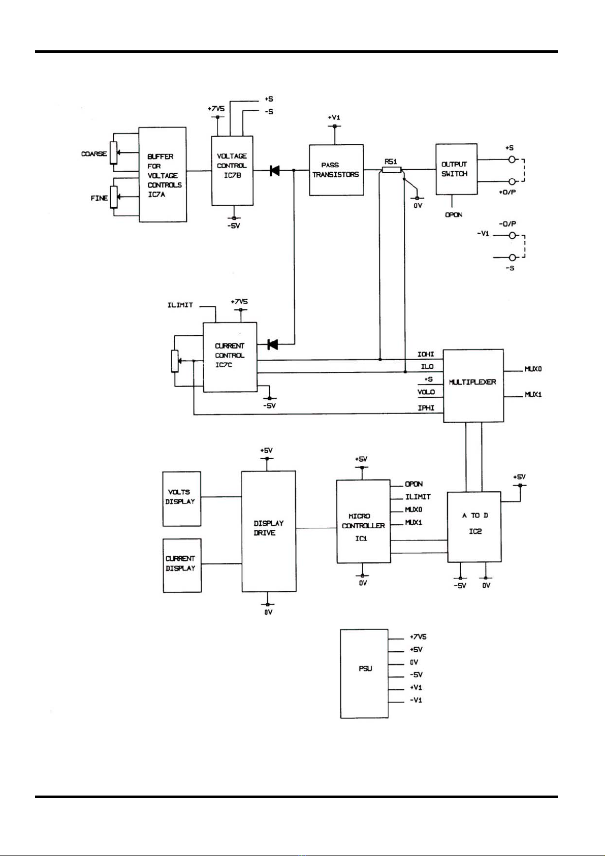
Block diagram - Main Outputs
8

Functional Description – Main Outputs
The relationship between the major circuit elements is shown in the block diagram opposite.
The transformer incorporates two secondary windings, one which produces the main supply
powering the output, and another which produces an auxiliary supply powering the control and
metering circuits.
The series regulator is placed in the positive output of the main supply, but because of the way in
which the control and metering circuits operate, it is convenient to label the output of the series
regulator as 0 volts, and to regard the negative side of the main supply as being the controlled
output voltage (-V out).
The auxiliary supply provides stabilised symmetrical voltage outputs V+ and V- with the common
point connected to the +ve output.
The series regulator is controlled by the 'voltage control circuit' until the output current flowing
reaches the current limit setting, upon which the 'current control circuit' takes over. The voltage
control buffer amplifies and provides low output impedance from the voltage controls.
The input to the voltage control circuit is from the control buffer, or from the master output on the
slave side of PLQMD/PLQMT units.
The 12 bit A to D measures output voltage and either preset current or output current selected by
the multiplexer.
The micro-controller reads the output of the A to D and drives the appropriate display.
9

Circuit Description – Main Outputs
Refer to the appropriate schematic at the back of this manual.
Power Supply - Mains
This consists of a full wave bridge rectifier feeding the reservoir capacitor C31. The full load
secondary winding voltage is 36V rms giving approximately 55 volts off load and 40V on full load
(30V and 24V on PL154).
Power Supply - Auxiliary
This consists of twin full wave rectified supplies from a 21V centre tapped winding. IC8 generates
+5V for the micro-Controller, display and A to D. Q7 and D10 generate +7.5V for the analogue
section. D11 generates -5V for the analogue section and A to D. 0V of this supply is connected to
the positive output at R51.
Voltage Control
IC7A buffers the voltage control pots and VR3 sets maximum output voltage of the unit. D6 is the
reference which is nominally 2.45V.
IC7B is a differential amplifier with a voltage gain of 13.3. For 30V output this means the voltage
at PJ2-8 will be 2.25V and for 15V output 1.125V. VR9 trims differential gain and effects voltage
regulation. This can be set more accurately by generating a few hundred millivolts between
positive output and positive sense, see calibration section.
Current Control
IC7C is the error amplifier and compares the voltage on the wiper of VR5 with the voltage
generated across the current sense resistor R51. When this limit is reached IC7C takes control
changing the supply output from constant voltage to constant current. Current limit is indicated to
the micro-controller by ILIMIT going high. The sense resistor is 100 milli-Ohm, therefore with the
current limit set to 2A the voltage on the wiper of VR5 will be typically 188mV when VR7 is set
central. VR8 adjusts the output current to be the same as the preset current at low levels. VR4
trims maximum output current.
Series Regulator
Q1 and Q2 form a triple Darlington. On 2 Amp and 4 Amp versions Q2 is in parallel with Q3, Q4
and Q5. On 3 Amp versions Q2 is in parallel with Q3, Q4, Q5, Q8 and Q9. Q1 is a Darlington and
is on a heatsink on the driver pcb.
A to D
IC2 is a 12 bit dual slope converter. Its reference is derived from D6 by R27 and R28 and is
typically 180mV. XL1 is either a 4MHz crystal or ceramic resonator. The buffered oscillator
output is also used by the microcontroller IC1. Analogue multiplexer IC3 selects measurement of
output voltage, preset current or output current. R65 and C38 provide the current meter damping
facility.
Microcontroller
The measurement system and display is controlled by a microcontroller IC1.
The two 4-digit LED displays are driven by IC1 via the segment latches IC4 and IC9 and the digit
latch IC5. Digit current is provided by IC6 and individual segment current is limited to 50mA by
the resistors R10 and R17. The digit on-time rate is 2ms and is controlled by IC1 which also
provides the inter digit blanking to prevent ghosting segments.
The measurement of output values of voltage and current is performed by the 12 bit analog to
digital converter IC2. The measurement rate is controlled by the 4.0MHz ceramic resonator XL1
connected between pins 22 and 23 and the buffered version of this 4MHz signal at pin 25 is used
as the clock to the microcontroller IC1. The ADC, IC2, is a dual slope converter and provides a
little over 8 readings per second when clocked at 4MHz. The ADC is run in continuous mode and
10

the status signal on pin 2 is read by the microcontroller every 6ms. When a reading is ready the
microcontroller reads the 12 bit binary value and then converts it to 7 segment BCD and stores it
ready to be sent to the display. After each reading the microcontroller switches the input
multiplexer IC3 to the next required input. In this way it is possible to read and display any of the
following:
Output Volts (equal to Preset Volts when the output switch is off)
Output Current
Preset Current
The multiplexer is controlled by IC1. The decision on what to measure and display at any time is
taken by the microcontroller and in order to do this correctly a number of status signals and
switches are monitored on a regular basis. These are:
ILIMIT true if in current limit
OPON the output on/off switch signal
These signals may be read by the microcontroller as required.
Service Notes
On Issue 3 and earlier main pcbs the current damping was provided by a digital filter in the
microcontroller program and R65 and C38 were not fitted. Also if jitter is experienced on the
meters near full scale, this can be overcome by increasing C1 to 330n. If the integrator capacitor
C4 has high dielectric absorption this will cause non zeroing of the current meter; this can be
overcome by simply replacing it even with the same type as the yield is very good. On later pcbs
more space has been provided to allow the larger pitch polypropylene type to be used.
Poor regulation can be caused by incorrect adjustment of the differential gain or the output is
oscillating.
Quad Mode Dual Switchbank Assembly
The Quad Mode Dual units have a bank of four switches which allow four modes of operation to
be obtained.
Isolated: SW1 (Release) depressed. All interconnections between the two units is removed.
Parallel: SW2 depressed. The Slave unit pass transistors are driven from Q1 on the Master
PCB, and their output is combined with that of the Master unit, thus doubling its
current capability. VR5 on the Master unit is disconnected from R47 and connected
to a network generating twice the control voltage. The slave unit becomes
inoperative.
Series: SW2 depressed. The Slave unit positive terminal is connected to the Master unit
negative terminal.
Tracking: SW4 depressed. As for Series, but additionally R36 on the +ve input to the Slave
unit voltage control op-amp IC7B is disconnected from IC7A and is instead
connected to a potential divider connected between Master unit +ve output and
Slave unit -ve output. This maintains the voltageage at the Slave +ve output (and
hence the Master -ve output) equal to ½ of the total output voltage, thus producing
tracking supplies of ± 30V controlled from VR1 and VR2 on the Master unit. VR1
and VR2 on the Slave unit become inoperative.
PL330QMD Master
The main pcb on the master side on these instruments has some extra circuitry which allows
current measurement above 4 amps and is only active when parallel mode is selected, QMPAR
going low. IC10 halves the reference input to the A to D and selects VOL02 to give the correct
output voltage readings. The current readings only read half and the microcontroller multiplies
the answer by 2 before driving the display. This results in a resolution of 2mA and not 10mA which
would be the case if a divide by 10 was used. See calibration section for correct adjustment of
VR10 and VR11.
11

Calibration – Main Outputs
Equipment Required
A 5.5 digit multimeter with better than 0.05% accuracy on voltage and better than 0.1% accuracy
on current or use a precision current shunt.
A small switch, 18K resistor and a diode.
Preparation
Preset adjustments are accessible from both sides of the main pcb, their idents are also marked
on both sides of the pcb.
Take great care not to touch the mains connections on the transformers during adjustment. Use
an insulated trim tool. Allow five minutes warm-up before proceeding.
Calibration
To avoid errors when making voltage measurements the DVM must be connected directly to the
sense terminals.
Voltage - Differential Gain
Remove the link between + O/P and + sense only and fit a diode, cathode to + sense and anode
to + O/P. Connect the small switch across the diode. Connect the 18K resistor between - O/P
and + sense. Connect the DVM set to 20V range to the sense terminals.
Close the switch
Set the DC output switch on
Set the output voltage to approximately 14V
Note the reading
Open the switch and adjust VR9 for the same reading +/- 0.5mV
Close and open the switch and check the reading
Voltage - Output and meter
Remove the switch and 18K resistor and refit the link between +O/P and + sense.
Set coarse and fine controls to maximum and adjust VR3 to 32.1V or 15.6 on PL154 on the
external DVM.
Adjust VR6 so the internal meter reads the same as the DVM.
Current
Set output switch to OFF
Set the current limit control for a reading of 10mA
Set output switch to ON ON and short the output terminals
Adjust VR8 for a reading of 10mA
Remove the short and connect an ammeter between the output terminals.
Set current limit to approximately:
900mA - PL310
1800mA - PL320
2700mA - PL330
3600mA - PL154
and adjust VR7 so that the internal and external ammeters read the same.
12

Set current limit to maximum, output off and adjust VR4 for:
1100mA - PL310
2100mA - PL320
3100mA - PL330
4050mA - PL154
Quad Mode Calibration
The above calibration must be carried out first.
i)
PL310QMD/QMT and PL320QMD/QMT
Select parallel mode, output switches OFF
Master current limit to maximum
Adjust VR2 on switchbank pcb for
2100mA - PL310QMD/QMT
4050mA - PL320QMD
on the master ammeter
Select tracking mode, output switches ON
Set master output voltage to approximately 30V
Adjust VR1 on switchbank pcb so that the above voltmeter reads the same as the master
voltmeter.
ii) PL330QMD/QMT
Select parallel mode, output switches OFF
Set master current limit to approximately 5A
Master output switch ON
Connect ammeter between the master output terminals
Adjust VR10 on the master main pcb for the same reading on the internal and external ammeters.
Remove external ammeter and connect the DVM to the master sense terminals.
Set master coarse voltage control to maximum.
Adjust VR11 on the master main pcb for the same reading on the internal and external
voltmeters.
Note: In parallel mode, VR10 affects both the voltmeter and ammeter calibration; VR11 affects
only the voltmeter.
Output switches OFF
Master current limit to maximum
Adjust VR2 on the switchbank pcb for 6100mA on the master ammeter
Select tracking mode, output switches ON
Set master output voltage to approximately 30V
Adjust VR1 on switchbank pcb so that the slave voltmeter reads the same as the master
voltmeter.
13

Quad Mode Triples
Funcitonal Description - 5V/7A Module (PL330 QMT)
The relationship between the major circuit elements is shown in the block diagram.
The transformer incorporates two secondary windings, one which produces the main supply
powering the output, and another which produces an auxiliary supply powering the control and
metering circuits.
The series regulator is placed in the positive output of the main supply, but because of the way in
which the control and metering circuits operate, it is convenient to label the output of the series
regulator as 0 volts, and to regard the negative side of the main supply as being the controlled
output voltage (-V out).
The auxiliary supply provides stabilised symmetrical voltage outputs V+ and V- with the common
point connected to the +ve output.
The series regulator is controlled by the 'voltage control circuit' until the output current flowing
reaches the current limit setting, upon which the 'current control circuit' takes over. The voltage
control buffer amplifies and provides low output impedance from the voltage controls.
The 12 bit A to D measures output voltage with the output switch off and output current with the
output switch on selected by the multiplexer.
The micro-controller reads the output of the A to D and drives the display.
Circuit Description - 5V/7A (Issue 2 PCBs and later)
Power Supply - Mains
This consists of a full wave bridge rectifier feeding the reservoir capacitor C30. The full load
secondary winding voltage is 11V rms giving approximately 15 volts off load and 12V on full load.
Power Supply - Auxiliary
This consists of twin full wave rectified supplies from a 21V centre tapped winding.
IC8 generates +5V for the micro-Controller, display and A to D. Q7 and D10 generate +7.5V for
the analogue section.
D11 generates -5V for the analogue section and A to D.
0V of this supply is connected to the positive output at R62.
Voltage Control
IC7A buffers the voltage control pot and VR7 sets maximum output voltage of the unit. D9 is the
reference which is nominally 2.45V.
14

15
Block Diagram – 5V/7A Output (Issue 2 pcb onwards)

IC7B is a differential amplifier with a voltage gain of 13.3. For 6V output this means the voltage at
IC7A will be 450mV. VR4 trims differential gain and effects voltage regulation. This can be set
more accurately by generating a few hundred millivolts between positive output and positive
sense, see calibration section.
Current Control
IC9A is the error amplifier and compares the voltage on the wiper of VR3 with the voltage
generated across the current sense resistor R62. When this limit is reached IC3A takes control.
Current limit is indicated to the micro-controller by ILIMIT going high. The sense resistor is 50
milli-Ohm, therefore with the current limit set to 7A the voltage on the wiper of VR3 will be
typically 330mV when VR5 is set central.
To limit power dissipation in the series regulator the power supply has foldback current limiting.
When the power supply enters current limit the microcontroller also monitors the output voltage,
and if this falls below 3.5V IC6B is switched from VR2 to a simple 3 bit DAC so that the
microcontroller can take control of the current limit and reduce it as the output voltage falls.
Series Regulator
Q5, Q2 and Q3 form a triple Darlington. When the output current reaches 3 Amps, Q8 starts
conducting.
Over Voltage Protection
When the voltage on the output terminals exceeds 7V, SCR1 is fired crowbaring the output.
Current flowing through D6 is detected by IC9B which drives the trip line high informing the
microcontroller of the trip condition. The microcontroller then turns the series regulator off via Q4.
A to D
IC2 is a 12 bit dual slope converter. Its reference is derived from D9 by R29 and R30 and is
typically 180mV. XL1 is either a 4MHz crystal or ceramic resonator. The buffered oscillator
output is also used by the microcontroller IC1. Analogue multiplexer IC3 selects measurement of
preset voltage or output current.
Microcontroller
The measurement system and display is controlled by a microcontroller IC1.
The 4-digit LED display is driven by IC1 via the segment latch IC4 and the digit latch IC5. Digit
current is provided by IC3 and individual segment current is limited to 25mA by the resistors R10
and R17. The digit multiplex rate is 2ms and is controlled by IC1 which also provides the inter
digit blanking to prevent ghosting segments.
The measurement of output values of voltage and current is performed by the 12 bit analog to
digital converter IC2. The measurement rate is controlled by the 4.0MHz ceramic resonator XL1
connected between pins 22 and 23 and the buffered version of this 4MHz signal at pin 25 is used
as the clock to the microcontroller IC1. The ADC, IC2, is a dual slope converter and provides a
little over 8 readings per second when clocked at 4MHz. The ADC is run in continuous mode and
the status signal on pin 2 is read by the microcontroller every 6ms. When a reading is ready the
microcontroller reads the 12 bit binary value and then converts it to 7 segment BCD and stores it
ready to be sent to the display.
The output is electronically switched. The output from the unit bypasses the output switch (links)
and the OPON signal drives Q4 via inverter Q5. When OPON is low, Q4 is on and removes the
drive to the pass transistors. OPON also drives the multiplexer IC10 which switches to Vp when
OPON is low.
16

Calibration - 5V/7A Module
Equipment Required
A 5.5 digit multimeter with better than 0.1% accuracy on voltage and better than 0.2% accuracy
on current or use a precision current shunt.
A small switch, 560 Ohm resistor and a diode.
Preparation
Preset adjustments are located on both the main and driver pcbs. Presets are accessible from
both sides of the main pcb.
Take great care not to touch the mains connections on the transformers during adjustment. Use
an insulated trim tool. Allow five minutes warm-up before proceeding.
Calibration
To avoid errors when making voltage measurements the DVM must be connected directly to the
sense terminals.
Voltage - Differential Gain
Remove the link between + O/P and + sense only and fit a diode, cathode to + sense and anode
to + O/P. Connect the small switch across the diode. Connect the 560 Ohm resistor between
-O/P and + sense. Connect the DVM set to 20V range to the sense terminals.
Close the switch.
Set the DC output switch ON.
Set the output voltage to approximately 5V.
Note the reading
Open the switch and adjust VR4 on the main pcb for the same reading +/- 0.5mV.
Close and open the switch and check the reading.
Voltage - Output and Meter
Remove the switch and resistor and refit the link between + O/P and + sense.
Set the voltage control to maximum and adjust VR7 for 6.0V to 6.05V on the external voltmeter.
Note the reading and set the output switch to OFF, adjust VR8 on the main pcb for the same
reading on the internal meter.
Current
Set output switch to ON.
Set current limit control to maximum.
Set VR3 on the driver pcb fully clockwise.
Connect the DMM set to 20A range in series with an adjustable load to the O/P terminals.
Adjust the load for 5 to 6 Amp output current.
Adjust VR5 on the driver pcb so that the external and internal meters read the same.
Adjust the load and/or outputput voltage to give 7.1 Amps output current.
Fine adjust VR3 until the decimal points just start to flash. Check 7 Amps output can be achieved
without de decimal points flashing.
17

Functional Description - 5V/4A Module
(PL320QMT)
This is very similar to the linear section of the 5V 7A module. Refer to this section for the
description.
Circuit Description - 5V/4A
Power Supply - Mains
This consists of a full wave bridge rectifier feeding the reservoir capacitor C1. The full load
secondary voltage is 11V rms giving approximately 15Volts off load and 12V on full load.
Power Supply - Auxiliary
This consists of twin full wave rectified supplies from a 21V centre tapped winding.
D10 and Q5 generate +7V5 and D9 the -5V.
0V of this supply is connected to the positive output at R32.
Voltage Control
IC1A buffers the voltage control pot and VR5 sets maximum output voltage of the unit. D8 is the
reference which is nominally 2.45V.
IC1B is a differential amplifier with a voltage gain of 13.3. For 6V output this means the voltage at
IC1A will be 450mV. VR4 trims differential gain and effects voltage regulation. This can be set
more accurately by generating a few hundred millivolts between positive output and positive
sense, see calibration section.
Current Control
IC1D is the error amplifier and compares the voltage on the wiper of VR3 with the voltage
generated across the current sense resistor R32. When this limit is reached IC1D takes control.
This turns on Q1 which lights the current limit LED.
To limit power dissipation in the series regulator the power supply has foldback current limiting.
When the output falls below 3.5V IC1C reduces the output current by reducing the voltage on
VR3.
Over Voltage Protection
When the voltage on the output terminals exceeds 7V, SCR1 is fired crowbaring the output. When
the output switch is turned off, Q4 is turned on, which turns the series regulator off, which allows
SCR1 to turn off.
18

Calibration - 5V/4A
Equipment Required
A 5.5 digit multimeter.
A small switch, 560 Ohm resistor and a diode.
VOLTAGE - Differential Gain
Remove the link between + O/P and + sense only and fit a diode, cathode to + sense and anode
to + O/P. Connect the small switch across the diode. Connect the 560 Ohm resistor between -
O/P and + sense. Connect the DVM, set to 20V range, to the sense terminals.
Close the switch.
Set the DC output switch on.
Set the output voltage to approximately 5V.
Note the reading.
Open the small switch and adjust VR4 for the same reading ± 0.5mV.
Close and open the small switch and check the reading.
VOLTAGE - Output
Remove the switch and resistor and refit the link between ± O/P and + sense.
Set the voltage control to maximum and adjust VR5 for 6.0V to 6.05V output.
CURRENT
Set current limit to maximum.
Connect a load of 4.1A and adjust VR2 until the current limit LED just comes on; check the LED
is off at 4A.
Circuit Description - 5V/1.5A (PL310QMT)
An extra winding on the master output transformer provides approximately 8V rms off load. D1 to
D4 form a bridge rectifier and C1 and C2 the reservoir capacitor.
IC1 is a fixed 5V three terminal low drop out regulator, D5 and D6 provide protection.
No calibration is required, see Technical Specification section for performance figure.
19
Table of contents
Other TTI Power Supply manuals


