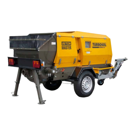
Turbosol Beton Master User manual

Serial number
READ THIS MANUAL CAREFULLY BEFORE USING THE MACHINE.
THIS MANUAL IS AN INTEGRAL PART OF THE MACHINE AND MUST BE KEPT FOR FUTURE REFERENCE
UNTIL THE MACHINE IS DISPOSED OF
OPERATION AND MAINTENANCE MANUAL
BETON MASTER
17341 - 561.184
EN IT
ORIGINALI

INDEX
THIS MANUAL IS PROPERTY OF - ANY TOTAL OR PARTIAL REPRODUCTION IS STRICTLY FORBIDDEN
1 CE DECLARATION .................................................................................................................................................1
1.1 CE DECLARATION OF CONFORMITY ...........................................................................................................1
2 GENERAL INFORMATION......................................................................................................................................1
2.1 IMPORTANCE OF MANUAL............................................................................................................................1
2.2 ABBREVIATIONS ............................................................................................................................................1
2.3 INFORMATION ON CONSULTING THE MANUAL..........................................................................................1
2.4 MEANING OF SYMBOLS ................................................................................................................................1
2.5 MACHINE OFF.................................................................................................................................................2
2.6 GENERAL AND CONTACT INFORMATION....................................................................................................2
3 TECHNICAL DESCRIPTION ...................................................................................................................................1
3.1 NAME OF MACHINE........................................................................................................................................1
3.2 DIMENSIONS OF MACHINE ...........................................................................................................................2
3.3 TECHNICAL DATA ..........................................................................................................................................2
3.4 INTENDED USES ............................................................................................................................................2
3.5 MATERIALS USED ..........................................................................................................................................3
3.6 NAME OF MACHINE PARTS...........................................................................................................................3
4 TRANSPORTATION AND HANDLING....................................................................................................................1
4.1 TRANSPORTING THE MACHINE AS A VEHICLE TRAILER.......................................................................... 1
4.2 LIFTING ...........................................................................................................................................................3
5 INSTALLATION ....................................................................................................................................................... 1
5.1 POSITIONING THE MACHINE ........................................................................................................................1
5.2 PIPING .............................................................................................................................................................1
5.2.1 Piping layout..................................................................................................................................................2
- Horizontal pumping ..............................................................................................................................................2
- Vertical pumping ..................................................................................................................................................2
- Downward pumping .............................................................................................................................................2
5.3 FITTINGS .........................................................................................................................................................3
5.3.1 Victaulic couplings ........................................................................................................................................3
5.4 CONNECTIONS...............................................................................................................................................3
5.4.1 Concrete grid and vibrator.............................................................................................................................3
5.4.2 Remote control..............................................................................................................................................4
5.4.3 Connections on shotcrete version.................................................................................................................4
5.4.4 Connecting the radio control \(optional\) .......................................................................................................5
6 SAFETY ...................................................................................................................................................................1
6.1 SAFETY DEVICES...........................................................................................................................................1
6.2 SAFETY SIGNS ...............................................................................................................................................1
6.3 PERSONAL PROTECTIVE EQUIPMENT........................................................................................................2
6.4 RESIDUAL RISKS............................................................................................................................................2

INDEX
THIS MANUAL IS PROPERTY OF - ANY TOTAL OR PARTIAL REPRODUCTION IS STRICTLY FORBIDDEN
7 USE AND OPERATION ...........................................................................................................................................1
7.1 OPERATING PRINCIPLE ................................................................................................................................1
7.2 PUMPABLE SLURRIES...................................................................................................................................1
7.3 CHECKS BEFORE START-UP........................................................................................................................2
7.4 CONTROLS .....................................................................................................................................................4
7.5 STARTING THE MACHINE..............................................................................................................................7
7.5.1 Accelerator pump ..........................................................................................................................................9
7.6 CLEANING THE MACHINE AFTER A WORK SESSION .............................................................................. 11
7.6.1 Washing the piping .....................................................................................................................................12
- Flushing with water ............................................................................................................................................12
- Flushing with compressed air ............................................................................................................................13
- Cleaning by reverse pumping ............................................................................................................................14
7.7 IMPORTANT WARNING................................................................................................................................14
8 MAINTENANCE.......................................................................................................................................................1
8.1 MAINTENANCE TO BE CARRIED OUT BY OPERATOR ...............................................................................1
- Checking the lubrication water level ....................................................................................................................1
- Checking the engine coolant level .......................................................................................................................1
- Checking the motor oil .........................................................................................................................................1
- Checking the engine air filter ...............................................................................................................................1
- Checking the diesel fuel level ..............................................................................................................................2

- Checking the hydraulic oil level............................................................................................................................2
- At the end of a work session................................................................................................................................2
8.2 REPLACING THE PUMPING PISTONS .......................................................................................................... 3
8.3 ADJUSTING THE S-VALVE.............................................................................................................................6
8.4 REPLACING THE WEAR DISC, THE WEAR PLATE AND THE S-VALVE .....................................................7
8.5 CHANGING THE FIRST OIL FILTER...............................................................................................................8
8.6 CHANGING THE SECOND OIL FILTER..........................................................................................................9
8.7 REPLACING THE ADDITIVE METERING PUMP ..........................................................................................10
8.8 TO BE CARRIED BY QUALIFIED PERSONNEL...........................................................................................11
8.8.1 Maintenance after 50 hours ........................................................................................................................11
8.8.2 Maintenance to be performed every month or every 125 hours..................................................................12
8.8.3 Maintenance to be performed every 250 hours...........................................................................................12
8.8.4 Maintenance to be performed every six months or every 500 hours ..........................................................12
8.8.5 Maintenance to be performed every year or every 1000 hours...................................................................12
8.8.6 Maintenance to be performed every 2500 hours.........................................................................................13
8.9 TOWING GEAR MAINTENANCE ..................................................................................................................13
9 SCRAPPING ............................................................................................................................................................1
9.1 GENERAL INFORMATION ..............................................................................................................................1
10 TROUBLESHOOTING.............................................................................................................................................1
10.1 PROBLEMS WITH THE ELECTRONIC BOARD ...........................................................................................1
10.3 OPERATOR'S INTERVENTION.....................................................................................................................2
INDEX
THIS MANUAL IS PROPERTY OF - ANY TOTAL OR PARTIAL REPRODUCTION IS STRICTLY FORBIDDEN
11 RESPONSIBILITY OF THE OPERATOR ................................................................................................................1
11.1 RESPONSIBILITY..........................................................................................................................................1
11.2 WARRANTY...................................................................................................................................................1

EN BETON MASTER 17341 - 561.184 1 - CE DECLARATION
Cap. 1 - Pag. 1/1
THIS MANUAL IS PROPERTY OF - ANY TOTAL OR PARTIAL REPRODUCTION IS STRICTLY FORBIDDEN
1.1 CE DECLARATION OF CONFORMITY
An original copy of the CE Declaration of Conformity is supplied separately from the manual.

EN BETON MASTER 17341 - 561.184 2 - GENERAL INFORMATION
Cap. 2 - Pag. 1/2
THIS MANUAL IS PROPERTY OF - ANY TOTAL OR PARTIAL REPRODUCTION IS STRICTLY FORBIDDEN
2.1 IMPORTANCE OF MANUAL
The present Operation and Maintenance Manual has been prepared following the guidelines contained in the relevant
European Directives. Its purpose is to provide a simple and full understanding of the subjects dealt with to the
persons authorized to operate and perform maintenance on the machine described. The manufacturer has prepared
this manual with the greatest care. However, should any operators find any part of the manual difficult to understand,
they should contact the manufacturer immediately and request explanations and/or further information in order to
avoid misunderstandings that might compromise the user's safety. Before using the machine, operators are required
to read and understand this manual in every part and strictly follow its instructions, in order to ensure their own and
others’ safety, to make the machine work at its full potential and to ensure a long-lasting and efficient service life to all
the machine parts. This manual should be safely stored and kept close to the machine at all times for immediate
consultation by operators.
Only specifically trained and authorized personnel may be allowed to operate and perform maintenance on the machine.
Operators must follow all the instructions regarding the prevention of accidents and the regulations on workplace safety in force
in the country of use.
The Manufacturer shall not be responsible for any damages resulting from changes made to the machine and/or from
unauthorized tampering.
Users are advised to take note of the machine’s serial number; it must be presented along with every request for technical
assistance or for spare parts, and will facilitate processing such requests.
This manual reflects the latest information available at the time of marketing the machine and should not be considered
inadequate only because newly acquired information may require its updating. Reprinting or reproducing this manual, in whole
or in part, is not allowed unless authorized by ourselves in writing.
THE MANUFACTURER DECLINES ANY RESPONSIBILITY FOR DAMAGES TO PERSONS, ANIMALS OR PROPERTY
CAUSED FAILURE TO OBSERVE THE INSTRUCTIONS AND WARNINGS CONTAINED HEREIN.
2.2 ABBREVIATIONS
ca. around min minutes
cap. chapter N. number
DPI device of individual protection pag. page
DX right par. paragraph
h times pos. position
EN European Norm RIF. reference
Es. example s second
FIG. figure SX left
max. maximum TAB. table
min. minimum v. see
TAB. 01
2.3 INFORMATION ON CONSULTING THE MANUAL
Boldface:
Highlights important parts in the text.
2.4 MEANING OF SYMBOLS
Information and warnings that are particularly important are indicated in this manual by the following symbols:
CAUTION: This symbol indicates safety regulations regarding the operator.
NOTE: This symbol indicates additional information regarding the operation under way.
DANGER: This symbol indicates an electric shock hazard.
IMPORTANT: This symbol indicates further useful information.

EN BETON MASTER 17341 - 561.184 2 - GENERAL INFORMATION
2- Pag. 2/2
THIS MANUAL IS PROPERTY OF - ANY TOTAL OR PARTIAL REPRODUCTION IS STRICTLY FORBIDDEN
Cap.
2.5 MACHINE OFF
Before carrying out any kind of maintenance and/or adjustments on the machine the engine MUST be switched off using the
ON/OFF button (FIG. 35-REF. 1).
2.6 GENERAL AND CONTACT INFORMATION
The BETON MASTER concrete pump can be supplied with a number of different accessories, therefore not all the parts
described in this manual may be actually installed on your machine.
The Customer Service department of Turbosol Production S.p.A. will be glad to provide any information you may need.
Turbosol Produzione S.p.A.
Via Volta, 1
31030 Pero di Breda di Piave (TV) - ITALIA
Tel. +39 - 0422 - 90.2.51
Fax +39 - 0422 - 90.44.08
website: www.turbosol.it
e-mail: [email protected]
TURBOSOL MACHINES
Turbosol machines are the result of years of experience and constant research. This wealth of expertise, together with a
special attention to quality, contributes to guarantee that Turbosol machines are built to last, are highly reliable and work with
low operating costs.
MAINTENANCE AND CARE
Proper maintenance and care are essential for the machine to work as designed. It is extremely important that users observe
the recommended maintenance intervals and carry out any maintenance required, both to keep the machine in perfect running
order and to preserve the validity of the warranty.
SAFETY
The safety rules should also be made known to the maintenance personnel, and the local regulations on safety and accident
prevention should be followed at all times.
OPERATOR TRAINING
Operators must receive specific training on the operations to be carried out.
TURBOSOL SERVICE
Please contact your TURBOSOL dealer for any information regarding machine malfunctions or requests for
spare parts.

EN BETON MASTER 17341 - 561.184 3 - TECHNICAL DESCRIPTION
Cap. 3 - Pag. 1/3
THIS MANUAL IS PROPERTY OF - ANY TOTAL OR PARTIAL REPRODUCTION IS STRICTLY FORBIDDEN
3.1 NAME OF MACHINE
CE Marking
123
kg k
FIG. 01
The machine's series (1), model (2) and serial number (3) are engraved on the nameplate, as well as its power rating.
Position of CE nameplate
The CE nameplate (FIG. 02-REF. 1) is affixed to the machine's casing.
Position of serial number
The machine's serial number (FIG. 02-REF. 2) is punched on the tank cover as well as on the nameplate.
Position of tow-gear plate
Versions equipped with type-approved towing gear have an additional serial number punching (FIG. 03-REF. 1) and a
nameplate with the type-approval data (FIG. 03-REF. 2).
The name of the Manufacturer is also punched in (FIG. 03-REF. 3).
1
2
2
3
3
1
FIG.02 FIG.03

EN BETON MASTER 17341 - 561.184 3 - TECHNICAL DESCRIPTION
3- Pag. 2/3
THIS MANUAL IS PROPERTY OF - ANY TOTAL OR PARTIAL REPRODUCTION IS STRICTLY FORBIDDEN
Cap.
3.2 DIMENSIONS OF MACHINE
The following are the machine's overall dimensions and gross weight (in working conditions).
BETON MASTER D-E
LENGTH WIDTH HEIGHT WEIGHT*
3335
mm
1420
mm
1600
mm
1560
kg
TAB. 02
BETON MASTER D/T
LENGTH WIDTH HEIGHT WEIGHT*
4555
mm
1420
mm
1600
mm
1720
kg
TAB. 03
*Weight with full fuel tank and hydraulic oil tank and no optional accessories.
3.3 TECHNICAL DATA
Flow rate* m3/h 15
Maximum pressure on the concrete bar 80
Maximum number of cycles per minute - 30
Pumping cylinders (diameter x stroke) mm 120 x 700
Input power kW 37.3
Electric control plant power supply V 12 AC
Main hydraulic circuit maximum pressure bar 240/190
Auxiliary hydraulic circuit maximum pressure bar 180
Maximum particle size that can be pumped** mm 25÷30
Maximum useful distance*** m 150÷200
Maximum useful height*** m 100÷120
Flow collector inches 4.5
Hopper capacity litres 200
Diesel tank capacity litres 27
Oil tank capacity (hydraulic plant) litres 75
Hydraulic oil (recommended) ELF OLNA DS 46
Maximum height above sea level of the place of installation without sensitive loss of
the power m 1000
Acceptable environmental temperature °C -5° ÷35°
Guaranteed sound power level LwA dB 108
Endothermic motor: PERKINS 404D-22
Power kW 37.3
minimum 1550
Motor rpm maximum rpm 2900
Motor oil (recommended) TOTAL RUBIA TIR 7400
TAB. 04
* Theoretical.
** Maximum particle size 25 mm if aggregates obtained by crushing; maximum particle size 30 mm in case of spheroidal
aggregates.
*** Maximum values not simultaneously obtainable.
3.4 INTENDED USES
The machine has been designed and built for the following use:
FIELD OF USE: CONSTRUCTION WORK.
INTENDED USE: PUMPING SHOTCRETE AND CONCRETE

EN BETON MASTER 17341 - 561.184 3 - TECHNICAL DESCRIPTION
Cap. 3 - Pag. 3/3
THIS MANUAL IS PROPERTY OF - ANY TOTAL OR PARTIAL REPRODUCTION IS STRICTLY FORBIDDEN
3.5 MATERIALS USED
- Concrete with maximum particle size 25 mm if aggregates obtained by crushing; maximum particle size 30 mm in case of
spheroidal aggregates.
- Shotcrete.
3.6 NAME OF MACHINE PARTS
1
2
3
4
56
7
8
910
11
12
FIG. 04 *Figure shows towing gear.
13
14
15 16
18
23
19
21
20
22
17
FIG. 05
LEGEND
FIG. 04-REF. 1 - Casing FIG. 05-REF. 18 - Hydraulic pumping cylinder
FIG. 04-REF. 2 - Upper hopper FIG. 05-REF. 19 - Solenoid valves
FIG. 04-REF. 3 - Grid FIG. 05-REF. 20 - Switching jack control sensor
FIG. 04-REF. 4 - Vibrator FIG. 05-REF. 21 - Switching jack control sensor
FIG. 04-REF. 5 - Control column FIG. 05-REF. 22 - Pumping control sensor
FIG. 04-REF. 6 - Control panel FIG. 05-REF. 23 - Pumping control sensor
FIG. 04-REF. 7 - Towing gear*
FIG. 04-REF. 8 - Exchanger
FIG. 04-REF. 9 - Engine
FIG. 04-REF. 10 - Hydraulic pump assembly
FIG. 04-REF. 11 - Mixer
FIG. 04-REF. 12 - Lower hopper
FIG. 05-REF. 13 - Delivery flange
FIG. 05-REF. 14 - S-valve
FIG. 05-REF. 15 - S-valve switching jack
FIG. 05-REF. 16 - Pumping tube
FIG. 05-REF. 17 - Water tank

EN BETON MASTER 17341 - 561.184 4 - TRANSPORTATION AND
HANDLING
Cap. 4 - Pag. 1/3
THIS MANUAL IS PROPERTY OF - ANY TOTAL OR PARTIAL REPRODUCTION IS STRICTLY FORBIDDEN
4.1 TRANSPORTING THE MACHINE AS A VEHICLE TRAILER
Only machines with a frame equipped with vehicle towing gear are allowed to circulate on public roads.
Always respect the rules of the road when towing the machine.
The machine cannot be used for carrying loads of any kind, not even the removable accessories used for its
operation (pipes, fittings, gaskets, etc.).
What to do before towing the machine
- Make sure the diesel engine is switched off.
- Remove all pipes and hoses connected to the machine.
- Close and fasten the casing and check the fasteners.
- Lower the towing wheel and raise the support legs (FIG. 06).
- Fasten the light bar in its towing position (FIG. 06).
1
4
2
5
1
3
FIG.06 FIG.07
- Check the efficiency of the drawbar, the hook on the vehicle and the coupling mechanism.
- Remove the safety pin (FIG. 07-REF. 1)
- Unscrew the handle (FIG. 07-REF. 2) completely.
- Pull the "stickers" off the side discs (with a strong upward pull, to the left and to the right). Use only the handle (FIG. 07-REF.
3) to adjust the height.
- The middle section can be adjusted upward by 50° and downward by 10° until it reaches the limit.
- Tighten and lock the handle.
- Insert the safety pin.
- Turn the lever to raise the towing wheel (FIG. 07-REF. 4).
- After approximately 50 km, stop and tighten the handle again.
- Connect the light bar cable and make sure it works.
- Insert the snap cable through the eyelet welded on the side (guide cable grommet) (FIG. 08-REF. 1) and fasten the snap hook
to the hole (FIG. 09).

EN BETON MASTER 17341 - 561.184 4 - TRANSPORTATION AND
HANDLING
4- Pag. 2/3
THIS MANUAL IS PROPERTY OF - ANY TOTAL OR PARTIAL REPRODUCTION IS STRICTLY FORBIDDEN
Cap.
Make sure the cable is long enough to handle bends in the road. If the cable is too short it might accidentally
pull the brake.
If there is no eyelet on the towing vehicle, wrap the cable around the stem of the trailer hitch and attach the snap
hook to the cable itself. If the trailer is accidentally detached from the vehicle, the cable will pull the parking
brake (emergency brake).
The cable must be correctly passed through the cable guide grommet in order for the emergency brake to work
properly.
1
FIG.08 FIG.09
- Release the parking brake and remove the chocks (FIG. 06-REF. 1).
Unhitching the machine from the towing vehicle
- Lower and block the towing wheel.
- Pull the parking brake.
- Unhitch the machine from the towing vehicle.
When unhitching on a slope, block the machine using the parking brake and the chocks so that it won't move
after unhitching.
BETON MASTER can also be carried on motor vehicles; loading, securing and transporting the machine on a
motor vehicle should always be done in compliance with the rules of the road. See paragraph 4.2, LIFTING, for
information on using lifting apparatus to load BETON MASTER on a vehicle.

EN BETON MASTER 17341 - 561.184 4 - TRANSPORTATION AND
HANDLING
Cap. 4 - Pag. 3/3
THIS MANUAL IS PROPERTY OF - ANY TOTAL OR PARTIAL REPRODUCTION IS STRICTLY FORBIDDEN
4.2 LIFTING
BETON MASTER is provided with four lifting points and supplied with a lifting beam (FIG. 10).
- Fasten the ropes to the lifting beam (FIG. 10-REF. 1) and to the four lifting points, attaching the shorter ropes to the hooks
shown in FIG. 10-REF. 2 and the longer ropes to the hooks shown in FIG. 10-REF. 3.
Use the lifting beam only for the lifting of Beton Master.
Don't use the lifting beam to lift any other load.
Before using the lifting beam, check its integrity and in case replace it.
1
2
3
FIG. 10
Lifting should be carried out in strict observance of all the relevant safety rules, and the equipment used must
be in good order and conforming to regulations. The lifting apparatus must be operated by specifically trained
and authorized personnel.
Use only hooks and ropes certified for lifting 2000 kg.
Make sure the area is clear of any bystanders before lifting the machine.
Do not stand under suspended loads.
To prevent damages to the machine, do not lift or lower it with abrupt movements.
Do not change the lifting hook's anchoring point.
Move the machine only over level surfaces; avoid sloping surfaces to prevent the risk of being hit by the
machine or crushed between the machine and fixed obstacles.

EN BETON MASTER 17341 - 561.184 5 - INSTALLATION
Cap. 5 - Pag. 1/5
THIS MANUAL IS PROPERTY OF - ANY TOTAL OR PARTIAL REPRODUCTION IS STRICTLY FORBIDDEN
5.1 POSITIONING THE MACHINE
Place the machine in a horizontal position; the maximum allowed gradient is 5°, both lengthwise and crosswise (FIG. 11).
140 cm 140 cm
120 cm
120 cm
FIG.11 FIG.12
- Place BETON MASTER at the point of the worksite where you can use the pipes and hoses to their full extension.
- Brake the machine and block the wheels using the chocks supplied.
- Make sure the machine is resting on its side support legs and then raise the wheel.
Be sure to leave a passageway all around the machine (FIG12) clear of any obstacles and with no potholes or
hazardous projections.
Do not use the towing wheel to support the machine during operation; the machine should rest on the side
support legs and the main wheels in a stable manner.
5.2 PIPING
Lay out the piping using the shortest lengths possible (to reduce handling time and limit wear) and make sure the pipes are in
good conditions.
Use rubber hoses only for the last section of the piping and for lengths no longer than 4 metres. using rubber
hoses elsewhere along the piping may compromise pumpability (causing water to separate from the concrete)
and increase the risk of clogging.
Use only original pipes and fittings. The pipes should be fitted by TURBOSOL PRODUCTION S.p.A. or by
companies expressly authorized by TURBOSOL.
TURBOSOL PRODUCTION S.p.A. shall not be held responsible for damages to persons or property caused by
using non-original piping or fittings.
Before starting to pump, make sure the hoses show no cracks or deformations on their inner surface.
Deformations on the inner surface of rubber hoses can lead to dangerous clogging.

EN BETON MASTER 17341 - 561.184 5 - INSTALLATION
5- Pag. 2/5
THIS MANUAL IS PROPERTY OF - ANY TOTAL OR PARTIAL REPRODUCTION IS STRICTLY FORBIDDEN
Cap.
5.2.1 Piping layout
BETON MASTER can pump slurries horizontally, upwards or downwards. Here below are a few general rules that should be
followed when setting up the various layouts.
1
FIG.13 FIG.14
- Horizontal pumping
In case of horizontal pumping simply lay out the pipe in the desired layout and connect it to the first section described above.
- Vertical pumping
Vertical sections should be fastened and supported by collars (FIG. 14-REF. 1).
- Downward pumping
Downward sections should be fastened and supported by collars (FIG. 15-REF. 1).
Measures should be taken to prevent the concrete from dropping too fast along downward sections, for example by installing a
curve and a reverse curve as in FIG. 15 or by laying out a sloping section.
With this kind of layout lubricating the pipes with slurry should be carried out as follows:
- introduce two pipe sponges into the first section of the piping (FIG. 16)
- pump the slurry
This will lubricate the entire downward section. If the downward section is very long, we recommend pumping additional
sponges and slurry.
1
2
BOIACCA
SPUGNE
DI LAVAGGIO
FIG.15 FIG.16

EN BETON MASTER 17341 - 561.184 5 - INSTALLATION
Cap. 5 - Pag. 3/5
THIS MANUAL IS PROPERTY OF - ANY TOTAL OR PARTIAL REPRODUCTION IS STRICTLY FORBIDDEN
5.3 FITTINGS
Make sure the fittings are clean and in good order at all times.
5.3.1 Victaulic couplings
When coupling pipe sections, make sure the rubber gasket is in place (FIG. 17-REF. 1) and tighten the levers all the way (FIG.
17-REF. 2).
1
2
FIG. 17
5.4 CONNECTIONS
5.4.1 Concrete grid and vibrator
Open the small door (on the side where the electronic control panel is located), connect the electric vibrator's plug (FIG. 19-
REF. 1) to the machine's socket (FIG. 19-REF. 2) located on the hydraulic oil tank and close the door.
2
1
FIG. 19

EN BETON MASTER 17341 - 561.184 5 - INSTALLATION
5- Pag. 4/5
THIS MANUAL IS PROPERTY OF - ANY TOTAL OR PARTIAL REPRODUCTION IS STRICTLY FORBIDDEN
Cap.
5.4.2 Remote control
The machine is supplied with a cable remote control. Plug the cable (FIG. 20-REF. 1) into the connector socket (FIG. 20-REF.
2) located on the machine's casing.
Turn the selector (FIG. 20-REF. 3) to 1 to start the mortar pump, to 0 to stop pumping and to 2 to reverse the direction of
rotation.
1
2
3
FIG. 20
5.4.3 Connections on shotcrete version
When pumping shotcrete you will need to use the shotcrete nozzle and the 15 mm slotted grid with the electric vibrator.
- Unscrew the shock absorber's anchoring bolts (FIG. 21.REF. 1).
- Remove the concrete grid, replace it with the shotcrete grid and fasten it to the shock absorbers using the bolts.
- Open the small door (on the side where the electronic control panel is located), connect the electric vibrator's plug (FIG. 22-
REF. 1) to the machine's socket (FIG. 22-REF. 2) located on the hydraulic oil tank and close the door.
- Connect the slurry delivery hose (FIG. 23-REF. 1) to the shotcrete nozzle and the air delivery hose (FIG. 23-REF. 2) to the
nozzle and to the auxiliary compressor.
1
2
1
FIG.21 FIG.22

EN BETON MASTER 17341 - 561.184 5 - INSTALLATION
Cap. 5 - Pag. 5/5
THIS MANUAL IS PROPERTY OF - ANY TOTAL OR PARTIAL REPRODUCTION IS STRICTLY FORBIDDEN
Accelerating additives are harmful. Protect any exposed surfaces adequately.
Handle additives with care and follow the manufacturer's instructions.
1
2
1
2
FIG.23 FIG.24
- Connect the accelerator delivery hose to the upper quick-release coupling (FIG. 24-REF. 1) on the side of the machine;
connect the other end of the hose to the tank containing the accelerator.
- Make sure the accelerator drawing point is at least 50 cm above the coupling (FIG. 24-REF. 2).
- Connect the accelerator delivery hose to the quick-release coupling (FIG. 24-REF. 2) to the nozzle coupling (FIG. 25-REF. 1).
- Prime the accelerator pump as follows. Press AUTO/MAN (g1) on the control panel and select manual operation (the light (g3)
turns on to indicate manual operation). Press ON/OFF (g2) to prime the pump; stop it when the silicate appears inside the hose
(see par. 7.4 for a description of the controls).
5.4.4 Connecting the radio control (optional)
- Connect the plug (FIG. 27-REF. 1) to the connector socket (FIG. 27-REF. 2).
- Press the button (FIG. 27-REF. 3) to switch the remote control on and off.
- Press the button (FIG. 27-REF. 4) to start pumping. Press the button again to stop pumping.
- To reverse pumping (i.e., sucking the mix from the pipe on the hopper), make sure the button (FIG. 27-REF. 4) is turned to
ON and press the button (FIG. 27-REF. 5) for the time required.
2
4
5
3
1
FIG. 27

EN BETON MASTER 17341 - 561.184 6 - SAFETY
Cap. 6 - Pag. 1/2
THIS MANUAL IS PROPERTY OF - ANY TOTAL OR PARTIAL REPRODUCTION IS STRICTLY FORBIDDEN
6.1 SAFETY DEVICES
GRIGLIA DI PROTEZIONE ALL'INTERNO DELLA TRAMOGGIA SUPERIORE
All'interno della tramoggia superiore è presente la griglia che, oltre ad impedire l'accesso all'aggregato di dimensioni eccessive,
impedisce il contatto con la valvola a S. L'apertura della griglia arresta il pompaggio di calcestruzzo ed il movimento della
valvola a S.
GRIGLIA DI PROTEZIONE VENTOLA DI RAFFREDDAMENTO
All'interno del vano motore è montata una griglia di protezione della ventola di raffreddamento fissata con viti.
CARROZZERIA
La carrozzeria protegge dal contatto con le parti calde interne ed i componenti in pressione del circuito oleodinamico.
VALVOLA DI MASSIMA PRESSIONE DEL CIRCUITO OLEODINAMICO PRINCIPALE
Sulla pompa oleodinamica è presente una valvola di massima pressione che serve a limitare la pressione massima del
pompaggio e del movimento della valvola ad S.
VALVOLA DI MASSIMA PRESSIONE DEL CIRCUITO OLEODINAMICO AUSILIARIO
Sull' elettrodistributore è presente una valvola di massima pressione che serve a limitare la pressione massima del circuito
ausiliario.
MANOMETRO PRESSIONE DEL CIRCUITO OLEODINAMICO PRINCIPALE
Il manometro è posto nella zona di comando e serve ad indicare all'operatore la pressione di esercizio del pompaggio e del
movimento della valvola ad S.
MANOMETRO PRESSIONE DEL CIRCUITO OLEODINAMICO AUSILIARIO
Il manometro è posto nella zona di comando e serve ad indicare all'operatore la pressione di esercizio del circuito ausiliario.
PIEDINI DI STAZIONAMENTO
I piedini di stazionamento sono necessari per garantire una posizione stabile a macchina piazzata.
DO NOT UNDER ANY CIRCUMSTANCES TAMPER WITH, DISCONNECT AND/OR REMOVE ANY SAFETY DEVICES
FROM THE MACHINE.
DO NOT UNDER ANY CIRCUMSTANCES REPLACE ANY SAFETY DEVICES OR PARTS OF A SAFETY DEVICE
WITH NON-ORIGINAL SPARE PARTS.
CONSTANTLY CHECK THE PROPER OPERATION OF ALL THE SAFETY DEVICES INSTALLED ON THE MACHINE.
MALFUNCTIONING OR DAMAGED SAFETY DEVICES MUST BE REPLACED IMMEDIATELY.
6.2 SAFETY SIGNS
The safety signs are adhesive labels affixed outside and inside the machine.
The safety signs must be kept clean and clearly visible at all times.
E' obbligatorio sostituire la segnaletica di sicurezza deteriorata, facendone richiesta al fabbricante.
E' assolutamente vietato rimuovere o danneggiare la segnaletica di sicurezza applicata alla macchina.
A
B
REF. LABEL DESCRIPTION
ADanger Moving parts
BDanger High temperatures
FIG.28 TAB.07

EN BETON MASTER 17341 - 561.184 6 - SAFETY
6- Pag. 2/2
THIS MANUAL IS PROPERTY OF - ANY TOTAL OR PARTIAL REPRODUCTION IS STRICTLY FORBIDDEN
Cap.
6.3 PERSONAL PROTECTIVE EQUIPMENT
Wearing personal protective equipment is mandatory, in compliance with the workplace health and safety regulations in force in
the country of use.
Employers, directors and operators must be acquainted with and enforce these regulations.
USING THE PROTECTION DEVICES INDICATED BY THE MANUFACTURER IS MANDATORY (TAB. 08).
MANDATORY SIGNS DESCRIPTION
IT IS MANDATORY TO PROTECT THE EYES..
IT IS MANDATORY TO PROTECT HEARING.
IT IS MANDATORY TO PROTECT THE
HANDS.
IT IS MANDATORY TO PROTECT THE FEET.
TAB. 08
6.4 RESIDUAL RISKS
Following the instructions and recommendations contained in this manual will allow you to use the machine correctly and
reduce any residual risks.
IN PARTICULAR:
Read the operation and maintenance manual before starting the machine.
Operators on the machine and on the slurry delivery end must be trained to carry out their work following the instructions
contained in this manual.
All maintenance must be carried out with the machine switched off.
PARTS UNDER PRESSURE::
Inspect the piping and make sure there are no signs of damage.
Make sure all the quick-release couplings and pipe joints are tight.
Make sure the vertical piping fasteners are securely fastened.
Do not open pipe fittings when the pipe is under pressure.
HOT PARTS:
Do not open the casing while the machine is running.
Do not touch the diesel engine silencer.
MOVING PARTS:
Do not open the casing while the machine is running.
Do not lift the hopper protection grid while the machine is running.
Do not introduce foreign matter through the grid.
Other manuals for Beton Master
1
Table of contents
Other Turbosol Construction Equipment manuals

Turbosol
Turbosol GIOTTO User manual

Turbosol
Turbosol GIOTTO MONO User manual

Turbosol
Turbosol POLI T Specification sheet

Turbosol
Turbosol BM 30 User manual

Turbosol
Turbosol MINI AVANT User manual

Turbosol
Turbosol UNI 30 E User manual

Turbosol
Turbosol Beton Master User manual

Turbosol
Turbosol PRO H CL Specification sheet

Turbosol
Turbosol TSR 7 User manual